GSJ: Volume 8, Issue 1, January 2020, Online: ISSN 2320-9186
www.globalscientificjournal.com
Computer Based Power analysis
Dr.J.Rajan,CSE,
Electrical and Computer Engineering, Mekelle University,
Ethiopia.
E-MailID:[email protected].
Abstraction: The aim of this Computer based Power Analysis has focused at building a compact scheme for monitoring the parameters and to protect the generator by replacing the relays into various transducers and are interfaced with the Personal Computer (PC) and the generator protection is implemented by means of a single computer using the time sharing scheme.
In Thermal power plants various inter locks and protections are used for safeguarding generator, boiler, turbine, coal feeders etc., Hard-wired logic gates are used in the most of the existing power plants.In the present scenario of computer era, even the core electrical parts have been replaced with the help of computer. So, in my PC based power analysis I have replaced some of the core parts such as generator protection relays with help of transducers and computer.
The input circuit comprises of Transducers and A/D converter, the output circuit comprises of dividing circuit for buzzer, Siren for the generator breaker. The input and the output circuits are connected to the PC through the interfacing card .All the transducers are connected to the PC through an A/D converter. The out of the transducer has analog signals; these are converted into digital signals through the A/D converter. From the PC, address has assigned to each of the transducers so that the PC can identify the signal from the transducers. The transducers always interact with the PC”s so that all the parameters of the generator can be monitored, when over a fault arises that will be intimated by the corresponding transducers and the PC identified that signal or fault by the addressed assigned by it. When the PC identifies a fault, the status of the fault has sensed according to the status the PC commands the driving circuit to drive the buzzer, Siren, and breaker. If any fault initiated then the PC gives command to the buzzer driving circuit to give annunciation. If the fault has at emergency state then the PC gives command to the Siren driving circuit to get alert. If the fault has severe it automatically trips the generator by commanding the generator breaker driving circuit, so that the generator will be protected. Implementing the PC in the field of generator protection improves the reliability, sensitivity and fault clearing time
Key words: A/D converter, PC, PCB, Rotor protection, Frequency Transducer. Thermal Transducer, Relay board, Power board
Fig-1, Design structure of the Power analysis
1.
Introduction: The increase size of generators and greater in their outputs by most efficient method of cooling, make it important to protect them against faults. The generator capacity has steeply rises in recent times from 30 MW to 500 MW. Even the loss of single unit can cause overloading of other machines and eventual system instability. Therefore the basic function of protection applied to generator has to reduce the outage period and to minimize the repair cost if any and to maintain systems stability. It has mainly focusing on protective scheme especially sensing elements called relays. The only way to reduce hardware and cost has to convert hardware based relays into software based relays for this; it has first converting all individual relay characteristics into software using “C++” language. In next step, I have visually/graphically-representing variation of all generator parameter in PC using Turbo C++ Graphics and I have dynamically monitoring all signal status. For sensing all parameter such as stator current etc., it has specially designed printed Circuit Board (PCB) for all parameter. All sensed parameter has sending to Personal Computer (PC) through Analog to Digital Converter (ADC) 0809 and each parameter has unique address location. And it has communication between my projection model and PC has made through specially designed“ADD-O In real time application, it has difficult to convert certain hardware-based relay in to software-based relays such as earth fault relay. It has retaining this relays and for communication with PC, and It has special type of relays for isolating faulty part and using specially designed drive circuit. The general block diagram for the above-discussed concept has shown in fig 1 as follows.
It has to simulate the fault, a potentiometer has employed after the capacitor in order to vary the voltage and its output has given to the preset. Another potentiometer has used to the circuit to vary the rotor current. The 8 bit digital signal has given to computer through the INTERFACE CARD. In computer the 8 bit signal has compared with predefined in the program, If the signal exceeds the predetermined value, computer gives a signal to drive circuit. In Thermal power plants various inter locks and protections are used for safeguarding generator, boiler, turbine, coal feeders etc., Hard-wired logic gates are used in the most of the existing power plants. In the present scenario of computer era, even the core electrical parts have been replaced with the help of computer. So, in my power analysis I have replaced some of the core parts such as generator protection relays with transducers and computer.
2. Methodology: The present methodology has
plant The energy production has can increase using the better quality data logger. Who has to establish thermal plant by using sensor via software based controlling system has more sensible to reduce the cost of production in electric power which are cheaper as compared to small plants. We have mainly focusing on protective scheme especially sensing elements called relays. The only way to reduce hardware and cost has to convert hardware based relays into software based relays for this; at first converting all individual relay characteristics into software using “C++” language. In next step, it has visually/graphically-representing variation of all generator parameter in PC using Turbo C++ Graphics and it has dynamically monitoring all signal status. For sensing all parameter such as stator current etc., it has specially designed PCB for all parameter. All sensed parameter has sending to PC through ADC 0809 and each parameter has unique address location. We have retaining this relays and for communication with PC, and It has using special type of relays for isolating faulty part, and it has specially designed drive circuit. The general block diagram for the above-discussed concept has shown in fig 1. In the present scenario of computer era, even the core electrical parts have been replaced with the help of computer. So, in the controlling system analysis Ii has replaced some of the core parts such as generator protection relays with transducers and computer.
3. Advantages:
*Relays are eliminated by transducers.
*all the parameters of the generator can be monitored from the screen.
*annunciation will be heard if any error signal is identified.
*error status can be viewed.
*at emergency generator is automatically tripped. *implementing any further protection and interlock is essay and possible.
4. Planning:
©To convert the existing hardware based relay circuits and protection in to power analyzed a PC based control system.
©To avoid the delay in tripping due to logic component and other reasons.
© Earlier location of faults and thus better safeguarding of ALTERNATOR.
©To ensure safety of personal and equipment, since because the equipments used are of high cost. ©To protect equipments from short term and long-term failure
© For continuous monitoring of parameters.
5. Problem Definition: In conventional generator protection relays are used to sense the fault and to trip the fault circuit. But the relay based protection has certain limitations. Some problems with conventional relays are
Slow in protection
Rectification of fault has a tedious job High cost
Occupies more space
Designed value cannot be altered.
6 Objectives:
We compared the solar, gas and wind energy and know how gas, wind and solar resource provided energy to fulfill the load requirement. Using the solar thermal and gas, wind energy has can reduce the pollution. It has sure that combined solar thermal and gas/wind has cost effective and it has much economical worthy. By using software control system to control entire the combined power plant In conventional generator protection relays are used them to sense the fault and to trip the fault circuit through PC. But the relay based protection has certain limitations.
7. A. Objective of the Research: over the years numerous studies have been conducted in solar collector field producing extensive material and valuable experience on different control procedures. This wide source of information and experience on controlling can be analyzed using development and turning environment. For diagnostically purposes, the software has extended by including additional features. The controller adjusted to operate in changing conditions by introducing extended feedback approaches where predicated disturbances are compared with the present situation which is known by the controller
7. B.Importance of Protection: With the advent of latest technology and more innovative ideas high capacity generators are in operation, which has very high cost. In order to protect those extreme machines my latest design can be employed for protection of generator by the PC
Fig1, Design structure for control system
Design feature of out project is broadly subdivided in to two parts and they are
8.1. Hardware design 8.3. Software design
Hardware design consist Transducer, software design comprises of programming features, which in turn governs the parameters of generator.
8.1. The Hardware configuration: The hardware used is PCB in which all input and output circuits are incorporated. The PCB’s are designed for Power Board and Drive Circuit
FIg-2. Power Board
Fig-.3, Circuit Board
8.1.1. Circuit Board: The above figure-3, the drive circuit diagrams. Drive circuit generates trip signal. Which has given to circuit breaker to remove the faulty part from the circuit as soon as computer senses fault? The signal from the computer has given to input of the drive circuit as binary signals (1’s and 2’s) Under normal condition the relay remains at normally open position and if the input signal is 1 then the circuit acts to generate trip signal. If the base of the transistor has provided with input signal (binary signal 1) DC, emitter has grounded and collector gains negative potential. If the computer
senses the fault condition then the drive circuit forward the transistor and hence forming the closed path across relay supply there by relay has activated to generate trip signal. 230V AC available at the input of the relay has available at the output and has ratified to DC voltage using diode, capacitor acts a filter and trip signal has given to circuit breaker. Hardware design has consist of Transducer, software design comprises of programming features, which in turn governs the parameters of generator.
8.2. The Principals of system Hardware:
The basic hardware design has printed circuit board for various parameters protections, and some are given below
8.2.A. Stator voltage(AC voltage) 8.2. B.Stator current (AC Current) 8.2. C.Rotor voltage (DC Voltage) 8.2. D.Rotor current (DC Current) 8.2. E.Frequency Transducer 8.2. F.Differential Protection 8.2. G.Thermal Transducer 8.2. H.ADC
8. 2.A. Stator voltage protection (AC voltage)
Fig- 4. AC Voltage Protection Circuit
Working: The circuit for AC Voltage Protection has shown in fig-4.The step down voltage say 110 V or 230 V has given to the AC voltage protection circuit. In DC voltage transducer 110 V AC has given to the FWR where it has converted in to DC voltage. A
signal. The 8 bit digital signal has given to computer through INTERFACE CARD .In computer the 8 bit signal has compared with predefined values specified in the program. If the signal exceeds the predetermined value, computer gives a signal to drive circuit. In my power analysis to make it suitable for all kind of generator, I have designed circuit consisting of two4.7KW./5W resistors, 10KW In employ protection for small generator of output voltage 230V,
get the voltage drop and has given to the step down
has tapped from 0-6 leads.To ensure protection for high capacity generator has tapped through the voltage transformer and it has stepped down to a voltage of 110V, and supplied in the circuit. In this
its output has given to the step down transformer
transformer has tapped from 6-6 leads. 8.2. B. Stator Current Protection
Fig.5. A.C Current Protection Circuit.
Working: Fig. 5 shows the schematic sketch of AC Current protection circuit. In order to safeguard generator against over current and under current fault the stator current has tapped through current transformer of ratio 1000:1. If a generator has a stator current of about 6000A then current transformer will reduce it to 6A and it has given to the current transducer. In current transducer there has a current transformer, which is of rating 10:1, which reduces the current further in order to make it suitable for small electrical components. The secondary of the current tran
resister and a capacitor acts as a filter. The output of the preset, which has in the range of (0-10V) has given to ADC..In ADC the Analog voltage signal has connected to 8 bit digital signal.
8.2. C.DC Voltage protection circuit
Fig-6.DC Voltage protection circuit
signal exceeds the predetermined value, computer gives a signal to drive circuit.
8.2. D.DC filed current:
Fig.7. DC Current Protection
Working: The DC field current protection has shown in figure 7.The DC field current protection has obtained by simulation method. The protection circuit consist of variable potentiometer (10K) powered by 5v supply.. The variable point has connected to the ADC, which has been controlled by PC The simulation is employed such that the variation of voltage from (0-5)V will show a (0-300)A in the out [put .the protection has such that ,if the field current falls below 50A.
The 8 bit digital signal has given to computer through INTERFACE CARD. In computer 8 bit signal has compared with predefined values specified in the program. If the signal exceeds the predetermined value, computer gives a signal to drive circuit. 8.2. E. Frequency transducer
Fig.8. Frequency transducer circuit
Working: The fig-8 shown above illustrates the frequency transducer circuit. The input supply 230v
has stepped down to 6v using step down transformer and it has fed as input to IC LM2917 to measure the frequency form the generator. This frequency waveform has now converted into pulses. The pulse width is proportional to the frequency input. It has being compared with known frequency and the difference has amplified and sent the output through a drive circuit.The output has DC voltage of the range has (0-5)v. This voltage has fed to the computer through ADC and Interfacing Card and wherever there has any variation in the frequency, and then a Trip signal has given to the drive circuit by the computer to uard the generator.
8.2. F. Generator Overall Differential Protection
Fig .9, Differential Protection Circuit
Working: The circuit has shown in fig-9 The overall differential protection of the generator for the single phase has as above. Connecting Two CT has on both sides of the stator windings employs the protection. One of which has of 10:1 ratio (CT1) connected at one end, where as one has obtained by simulation method. The current transformer CT1 and CT2 are matched. so that no current flows through the relay coil. If the fault occurs in between CT-1 and CT-2 the difference of current flows through the relay coil and it opens the generator circuit breaker.
8.2.G. Thermal transducer
8.2. G.1. Temperature measurement:
There are, in general, four types of sensors based on the following physical properties, which are temperature dependent: Expansion of a substance with temperature, which produces a change in length, volume or pressure. In its simplest form this has the common mercury in-glass or alcohol-in-glass thermometer.
Changes in contact potential between dissimilar metals with temperature; thermocouples.
Changes in electrical resistance with temperature, used in resistance temperature detector and thermistors.
Changes in current with temperature, AD-590, two terminal semiconductor type. 8.2. G.2. Resistance Temperature Detector (RTD): BASIC THEORY: RTD works on the principle that electrical resistance of the most metals increases linearly with temperature. If a metal wire has a
will be given by
of resistance. Typical values are:
Table - .1,RTC
A temperature transducer using the above principle has called Resistance Temperature Detector (RTD). These are simple to use, requiring special wiring, are highly stable and very sensitive. RTD’s commonly use platinum, nickel and copper to form the sensor, although iron, tungsten and alloys can be used. The former metals have the advantage they can be obtained to high degrees of chemical purity. Requirements of a conductor material to be used in RTD. The change in resistance of material per unit change in temperature should be as large as possible. The material should have a high value of resistively so that minimum volume of material has used for construction of RTD. The resistance of material should have a continuous and stable relationship with temperature.
8.2. G.3 Types of RTD:
8.2. G.3.1. Copper sensors: They are an obvious candidate, as copper is readily available at high degree of purity and has quite linear. High temperature measurements are limited to about
and hence bulky lengths of fine wire are required and the resulting relatively low resistance obtained makes
accurate measurement difficult. Copper has also very susceptible to oxidation and corrosion.
8.2. G.3 2. Nickel sensors: They are appreciably non-linear, restraining measurements to less than 300'c, although passive networks can be added to give linear outputs with temperature. However, temperature cycling through the Curie point at 358'c causes resistance instability. The resistively has allowing smaller devices to be reconstructed. As there has a little international agreement it's wider use has limited. Oxidation and corrosion has a problem. 8.2.G.3.3 Platinum sensors: They dominate resistance pyrometry. Platinum has stable, resists corrosion and oxidation, has malleable, has high melting point and high degree of resistivity, and can be made to high degree of purity. All these are achieved at the expense of high manufacturing costs and careful mounting to avoid strain gauge effects. 8.2.G.3.4. PRTD (Platinum Based RTD): Platinum based resistance thermometers are probably the most widely used. Measurements can be made from -220'c to 850'c. RTD has specified in terms of its resistance at 0'c, and change in resistance from 0'c to 100'c. This has known as "Functional interval" Platinum RTD's are constructed with a resistance of 100 ohms at 0'c has used in our design. This gives a resistance of 138.5 ohms at 100'c, and hence a fundamental interval of 38.5 ohms. RTD's are available in many shapes and sizes. The platinum resistance temperature detector (PRTD) has used today as an interpolation standard from oxygen point (-182.96'c) to antimony point (630.74'c). Platinum has especially suited for this purpose, as it can withstand high temperature while maintaining excellent stability. As a noble metal, it shows limited susceptibility to contamination.
8.2.G.4. Advantages of RTD: .More stable
Most accurate
More linear than thermocouple
8.2.G.5 Hardware of temperature measurement Components:
Thermistor Resistor
Fig .10, Thermal relay
Working: Thermal relay has one Resistor and a RTD (Resistance Temperature Detector) where both connected. The resistor value has selected so as the voltage drop across it & RTD has fairly equal at ambient temperature. When the temperature across RTD increases its resistance falls according to it resulting in the increase in voltage drop across the resistor. By calculating the voltage drop across the resistor the temperature across RTD can be calculated.
8.2. G .6. Lock out Relay:
Operate when the fault occurs.
Locks the computer screen with fault conditions
Even it has not reset normal conditions are restored after defect has rectified.
Values of all parameters at the time of fault are obtained.
Parameters are locked till it has reset.
8.2. H.6.The ADC 0809: The ADC 0809
interfacing device has a data acquisition interface universally known as an Analog to Digital Converter. This component has a CMOS device with an 8-bit analog – to – digital converter, 8 channel multiplexed and microprocessor compatible control logic. This device has widely used owing to its flexibility in programming. It has also used for configuring the device for various applications in real time. As an input, such as time varying signals. It has flexible, versatile and economical and can be interfaced with almost any microprocessor. The unique features of ADC 0809 include,
Easy interface to all Microprocessors.
Successive Approximation (SAR) type ADC.
No zero or full scale adjusts required.
8 nos. of analog input channels.
8-bit resolution parallel data.
0V to 5V input range.
Single 5V power supply operation.
ADC conversion time: 100ms.
Low power consumption – 15mW
Temperature range -40°c to +85°c or -55°c to +125°c
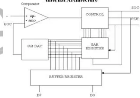
The symbolic representation of an ADC function has shown in fig-11. The time varying analog input at the ADC is converted to a digital data, which can be parallel or serial.
8.2. H.6.2. Successive Approximation: The
most widely used approach in A/D conversion has the successive approximation method. Before, the output of a ADC drives the inverted input of an operational amplifier (op-amp) comparator. The difference, however, has in how the SAR register converges on the digital equivalent. (SAR stands for Successive Approximation Register) When the conversion has finished, the digital equivalent has transferred to the output buffer.
Fig-11.ADC 0809 converter
has less than Vin, the +ve output of the comparator indicates that the MSB take place during first clock pulse following that soc. In other designs, several clock pulses may be needed to set the MSB, test it, and reset it if necessary.
8.2. H.4 Remaining Bits: Let us assume that the MSB was not reset. The SAR required contents are now 1000 0000. The next clock pulse will set 1100 0000. Vout now steps to 192/255 times full scale. If Vout has greater than Vin, the –ve op-amp output causes D6 to reset. If V out has less than V in, D6 remains set. During the remaining clock pulses, successive bits are set and tested. Whenever a bit causes Vout to exceed Vin, the bit reset. In this way, all bits are set, tested, and reset if necessary with the fastest circuits, and the D/A outputs has the Analog equivalent of the required contents. Slower designs take longer because more clock pulses are needed to set, test and possibly reset each bit.
8.2.H.5 Output Buffer: When the conversion has finished, the control circuit sends out a low end of conversion signal. The falling edge of this signal loads the digital output will remain even though we start a new conversion cycle.
8.2.H.6 Advantage of Successive Approximation: The main advantage of the successive approximation method has speed. At best, it takes only n clock pulses to produce n-bit resolution of the analog signal. This has a big improvement over the counter method. Even with slower designs, the successive approximation method has still considerably better than counter method.
8.2.H.7 Functional Description:
8.2.H.7.1 Multiplexer: The ADC0809 device has an 8-channel signal-ended analog signal multiplexer. Any one of the 8 channels can be selected using the 3 input channel select lines ADDA. ADDB & ADDC on pins 25,24 & 23 respectively. ADDA is the LSB and ADDC has the MSB table shows the input states for the address lines to select any channel. The address has latched in to the decoder on the low-to-high transition of the address latch enable signal. 8.2.H.7.2 Converter Characteristics: The heart of this single ship ADC has its 8-bits analog–to–digital converter is partitioned into 3 major sections:
The 256R Ladder network.
The successive approximation register.
The comparator.
8.2.H.7.2.1 256R Ladder Network:The 256R ladder network approach has an inherent monotonicity, which guarantees no missing digital codes. Monotonicity is particularly important in closed loop feedback control systems. A non-monotonic relationship can cause oscillations that will be catastrophic for the system. Additionally, the 256R network does not cause load variations on the reference voltage. The first output transition occurs when the analog has reached +1/2 LSB and succeeding output transitions occur every 1 LSB later up to full-scale.
5.2.H.7.2.2TheSuccessive Approximation Register (SAR):This performs 8 iterations to approximate the input voltage. For any SAR type converts n-iterations are required for an n-bit converter. The A/D converter’s successive approximation register (SAR) is reset on the positive edge of the start conversion pulse. A conversion in process will be interrupted by receipt of a new start conversion pulse continuous conversion may be accomplished by trying the end-of-conversion (EOC) output to the SC input. If used in this mode, an external start conversion pulse should be applied after power up. End of conversion will go low between 0 and 8 clock pulses after the rising edge of start conversion.
8.2. H.7.2.3, Comparator: The most important section of the A/D converter has the comparator. It has this section, which has responsible for the ultimate accuracy of the entire converter. It has also the comparator drift, which has the greatest influence on the repeatability of the device. A chopper-stabilized comparator provides the most effective method of satisfying all the converter requirements.The chopper-stabilized comparator converts the DC input signal into an AC signal. This signal has then fed through a high gain AC amplifier and has the Dc level restored. This technique limits the drift component of the amplifier since the drift has a DC component, which has not passed by the AC amplifier. This makes the entire A.D converter extremely insensitive to temperature; long term drift and input offset errors.
ADC is limited by the ±1/2 LSB quantized error plus the other errors of the system.
8.2. H.9.Speed: The speed of the Analog to digital converter has another very important specification and has defined as:
The time required to perform on conversion (or) The maximum possible time between successive conversions
It is determined by the settling time of components and the internal speed of the logic.
8.3. SOFTWARE DESIGN 8.3.1 Software Requirements 8.4. Software Design
8.5. Algorithm
8.3.1 Software Requirements
LANUAGE USED TRUBO-C++ OPERATING SYSTEM MS DOS/ WINDOWS
8.3,2. The Development of the C++ Language:C++ has an objected oriented programming language .It had developed by Bjarne Stroustrup at AT & T Bell Laboratories in Murray Hill,Vew Jersey, U.S.A, Simula 67 and a strong support of C, wanted to combine the best of the both the languages and create a more powerful language that could support object- oriented programming features and still retain the power and elegance of C at the result had C++ therefore++ has an extension of C with a major addition to the original C language. C++ has a superset of C most of what had already knows about to C++ also. Therefore ,almost all C programs are also C++ programs, However, there are a the most import facilitation But C++ adds on to C are classes, inheritance, function –over loading and operator over loading, There are features enable creating of abstracts data types, inherit proportion from exiting data types and support polymorphism, there by C++ a truly object-oriented language.The objected oriented in C++ allow programmers to build large programs with rarity, extensibility and case of maintenance, incorporating the spirit and efficiency of C. The addition of new features has transformed C, From C language that currently facilitates top-down, structured design, to one that provides bottom-up, object-oriented design. C++ can be used to build a variety of systems such as editors, compilers .data bases, communication system, and many more complex real-life application system C++ supports
inherent input output features and introduces a new comment symbol that can be used for triangle line commands. It also supports C-style comments.Like C programs, execution of all C++ programs begins at main () function and ends at return () statement. The header file in stream should be included at the beginning of all programs that use input / output operations.All ANSI C++ program would contain four basic section, class declaration section, member function and function section.. Like C programs, C++ programs can be created using text editor. Most compiler systems provide an integrated environment for developing and executing programs, popular systems are UNIX AT&T C++, Turbo C++ and Microsoft Visual C++
8.4. Software Design
Fig--12, Flow Chart 8.5. ALGORITHM
Step 1 : Include all the required header files.
Step 2 : Define the address of the input and output ports used.
Step 3 : Define the, Set and No set conditions and the delays.
Step 8 : Process the INPUT values with the rated values
Step 9 : Check the trip logic is high.
Step 10 : If yes send the trip logic through the output port.
Step 11: Else, scan the inputs from the input port. Step 12: Check if space bar is pressed.
Step 13: If yes, close the graphical display and stop. Step 14: Else, scan the inputs from the input port. 9. Analysis of Problem in existing system; All large generator units are mostly transformer connected unlike other apparatus, operating a breaker to isolate the faulty generator has not sufficient to prevent further damage since the generator will continue to run to supply power to a stator and rotor winding until its field supply has suppressed and supply to the prime mover has stopped. Generator faults are due to insulation failure and abnormal running conditions. Insulation failure results in an inter-turn fault, phase to phase fault and earth fault.This protection covers a zone from generator neutral to the HV circuit breaker. However the phase shift and current transformation due to step up transformer should be taken into account. A biased differential relay with a setting of 20% and a bias of 20% is generally adequate.
10. Case study:The computer models of the control system have been developed. Computer software are performed on a variety of possible conditions, such as
sudden decrease/increase of insulation with constant cell temperature, slow decrease/increase of insolation with constant thermal temperature, variable
insolation and thermal temperature, and change of power commands with variable insolation and thermal temperature
11. Relevance of the research:Various nonlinear
features are adapted to changing operating conditions with software techniques. Tuning with different lumped and distributed parameter models improve performance of the controllers. The new software control technique has reduced considerably temperature differences between collector loops. Efficient energy collection was achieved even in variable operating condition.[]
12. Multilevel process control:The multilevel control system consists of a nonlinear Low Energy controller with some smart features for avoiding difficult operating conditions. The multilevel control system consists of a nonlinear LE or avoiding difficult operating conditions controller for obtaining smooth operation. The basic controller has a PI-type LE controller has nonlinear and it can be represented by the function: Difficult cloudy conditions were handled fairly well by the single software controller. The smart control actions are beneficial in smooth compensation of load disturbances without exceeding the safety limits of the collector system.
13. Literature Review:
To perform this study, it had necessary to understand thermal energy collection and its conversion into electricity, evaluation of electrical performance, and the current efforts being made to improve conversion efficiency. The purpose of thermal energy collection has for the output of power, measured in Watts (P=V x I, V=voltage, I=current). However, in order to study how factors affect this output, it has crucial to understand how this performance has evaluated. A study had conducted by the thermal Energy Centre under Tamil Nadu Electricity Board observing the performance of different separate thermal power setups for thermal Power plants in Chennai, Tamil Nadu.
14. Result: As the temperature increases, different forms of conversion become practical. Up to 600 °C, steam turbines, standard technology, have efficiency up to 41%. Above 600 °C, gas turbines can be more
efficient. Higher temperatures are problematic because different materials and techniques are needed. One proposal for very high temperatures is to use liquid fluoride salts operating between 700 °C to 800 °C, using multi-stage turbine systems to achieve 50% or more thermal efficiencies.
14. Conclusion
control the unit.The ability to using PC to control over the thermal power plant has based on the software, .By this method has giving a better performance than Hardware (really) based controlling system. In future, we may replace it relays based hardware in the controlling system full and fully and implement software language controlling system has fully.
Reference:
[1].Allen-Bradley, Modern control technology, computer and systems, Omega engineering publications, Ins, Standford,1998.
[2].Gang Feng and Rogeliolozano, Adaptive control systems, Reed Educational & professional publishing Ltd, UK, 1999.
[3].Roland S Burns, Advance control engineering, Roland S. Burns publications, U K. 2001.
[4]. Nagoorkani. A, Control systems, RBG publications, Chennai.1998.
[5].Chandra Sekaran.A and Raja Sekaran. S, Engineering maths, Dhanm publications, Chennai, 2006.
[6] K.C. Kalaitzakis and G.J. Vachtsevanos, “On the Control and Stability of Grid Connected
[7],Keating.D.A, Usher.M.J, Sensor and Transducers, Machillan Press Ltd,pp180-191,1996.
[8]ShinskeyF.G, Process Control system (application, design, Turing) Mc, graw Hill, library of congress cataloguing-in-publication data,p-277,1996. [9]John J.Paserba, Juan J.Sanchez- gasca and Einar V.Larsen GE Power Systems Engineering, Schenectady, Ny, Control Electrical power, CRC press, Boca Raton London, Newyork, Washington DC,p-283,1999.
[10], Thomas H.Mc closkey, Handbook of Turbo Machinery (stream Turbines), Marcel,Dekker, INC.Newyork,Basel,p-427,2003