Optimization of the control loops of the variable
frequency induction motor drive of the flame reactor feed
screw
Yu.N. Dementyev
1*, I. Vajda
2, N.V. Koyain
1, K.N. Negodin
1, K.V. Obraztsov
11Tomsk Polytechnic University, Institute of Power Engineering, av. Lenina, 30, 634050, Tomsk, Russian Federation 2Óbuda University, Kandó Kálmán Polytechnic, Bécsi út 96/B, 1034, Budapest, Hungary
Abstract
In the paper the optimization of the control loops of the variable frequency induction motor drive for the feed screw of a flame reactor has been carried out to obtain required dynamic characteristics of the electric drive for known parameters of the plant. Simulation studies of basic control loops (current, flux-linkage and speed) are performed and dynamic parameters of control quality are presented. Results of the studies show that the obtained parameters meet requirements of the workflow and the modern variable-frequency drive based on induction motor can be implemented for actuating the feed screw of flame reactor. It should also be mentioned that transients quality factors in speed loop with input filter are better than without it.
Keywords: variable frequency induction motor, electric drive, optimization, control loop.
Received on 28 May 2017, accepted on 03 July 2017, published on 11 July 2017
Copyright © 2017Yu.N. Dementyevet al., licensed to EAI. This is an open access article distributed under the terms of the Creative Commons Attribution licence (http://creativecommons.org/licenses/by/3.0/), which permits unlimited use, distribution and reproduction in any medium so long as the original work is properly cited.
doi: 10.4108/eai.11-7-2017.152765
1. Introduction
The workflow of uranium fluorination requires precise dosing of uranium oxide, reliability and safety of the electric drive of feed screw. The technological process need to be controlled in real time mode, since the accurate proportion of the dosed solid powder of uranium oxide and the gaseous fluorine is needed to maximum degree of uranium extraction into UF6 while minimum consumption of fluorine. If the techno-logical parameters of uranium oxides fluorination are not close to the normal values, the dynamics of the burning process is altered, and the corrosion rate for construction materials of the flame reactor is in-creased, which causes shortening of its life. The dosing process of radioactive uranium oxides into a covered by a protection coating apparatus (flame reactor) is carried out by indirect volumetric method by controlling the speed of feeding screw. That is why we need to control both its speed and mechanical torque on its shaft.
Currently, a DC motor is used as the electric drive of the screw, which serves to feed the flame reactor with uranium oxide in the form of fine-grained material. The feeder is
weigh and single-component batcher according to classification in [1], i.e. it measures the weight of the single bulked material. Another feature of the driven mechanism is its big value of distributed moment of inertia, as a feature of all “barrel” reactor feeders [2].
Disadvantages of the DC motor drive are the low reliability of the DC drive because of the brush-collector junction, maintenance complexity, high operating costs, large dimensions and weight. Using electric drive based on the induction motor with squirrel-cage rotor and the implementation of modern control methods provides high efficiency and performance of these drives. Extensive use of induction motor with squirrel-cage rotor in a general-purpose and specialized electric drives is caused by it’s high reliability due to the absence of brush-collector junction and permanent magnets, simple construction, small size and moment of inertia and no restrictions on switching from speed and current, etc. [3, 7-9].
Therefore, the development, research and implementation of modern variable-frequency drive based on induction motor for the flame reactor feed screw is relevant and meets the modern requirements [4, 10-12].
2
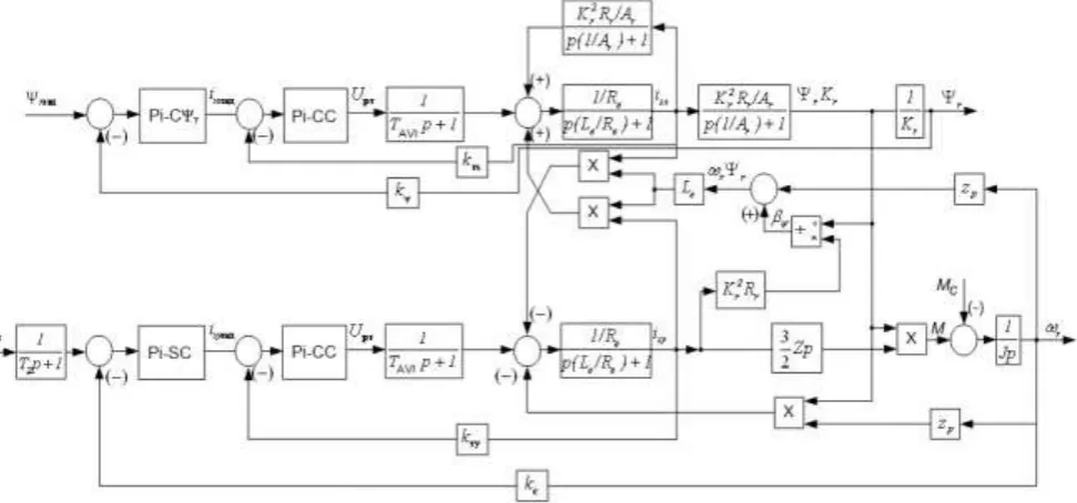
Figure 1. Simplified structure diagram of variable frequency vector control of the induction motor drive
From this diagram we can see that the system has control loops of the stator current X and Y components (with current controllers for each axis CCx and CCy), speed (with speed controller SC) and regulation loop, that determines the rotor winding flux (with flux controller FC.
3. Current loop optimization
Current loop optimization is performed without considering motor cross-couplings and with zero references for speed and flux. Loop structure diagram is shown in fig. 2.
Figure 2. Structure diagram of the loop for stator current component control
Considering the loop parameters a proportional-integral (PI) controller has been chosen.
The controller transfer function is expressed in terms of formula:
1
( ) CC ,
CC CC
CC p
W p k
p
where TCC TeTreg – time constant of the current
controller;
e CC reg
т Tx Tx
T R
k
a T k
– gain factor of the current
controller;
Tx
k – current feedback ratio,
m
a – current loop optimization ratio according to modular
optimum.
Transfer function of open current loop is given by:
1 ( )
( 1)
OpenCL
т т т
p
a T p T p
(3)
Transfer function of closed current loop is given by:
1 ( )
( 1) 1
Tx Closed CL
т т т
k p
a T p T p
(4)
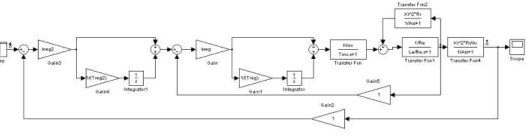
Figure 3.Current loop simulation model for stator current component isx control
Induction motor D09SA4 with following rated parameters is used for the electric drive simulation: Synchronous rotation speed n01500 rpm
, rated phase voltage U220
V , rated motor power РRAT 1.1
kW , rated slip S0.067, efficiency at rated power
76.3 %
RAT
, power factor at rated power
cos 0.78
RAT
, maximal-to-rated torque ratiomax
/ 2.7
MAX RAT
М М k , starting-to-rated torque
ratio М /М k 2.3
ST RAT ST , minimum-to-rated torque ratio МMIN /МRAT kMIN 2.1,
starting-to-rated current ratio IST /IRAT ki 5.1.
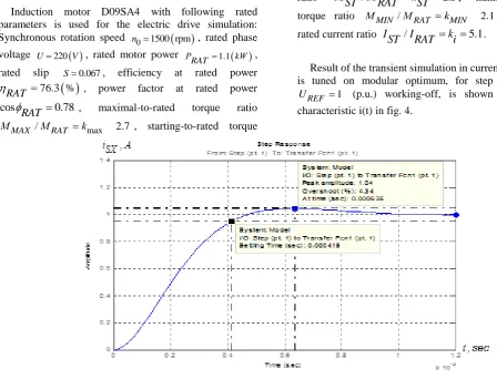
Result of the transient simulation in current loop, which is tuned on modular optimum, for step input signal
1 REF
U (p.u.) working-off, is shown as transient
characteristic i(t) in fig. 4.
Figure 4.Current loop transient characteristic i(t)
4 tuning with PI-controller is close to second-degree system tuning on modular optimum. This loop is first-degree astatic system for control signal.
4. Flux-linkage loop optimization
Structure diagram of flux-linkage loop is shown in fig. 5.
Figure 5. Structure diagram of flux-linkage loop
( 1) 1
Open FL
п т т т т т
a a Т p a Т p Т p
Overall transfer function of closed flux-linkage loop is given by
1 ( )
( 1) 1 1
Fr Closed FL
п т т т т т
k p
a a Т p a Т p Т p
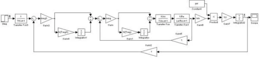
From flux-linkage loop structure diagram (see fig. 5) a simulation model that is shown in fig. 6 can be built.
Figure 6.Flux-linkage loop simulation model
Results of the transients simulation in flux-linkage loop, which is tuned on modular optimum, for step input signal
(V) working-off, are shown as transient characteristic r (t) in fig. 7.
Figure 7.Flux-linkage loop transient characteristic
Quality factors of the flux-linkage loop operation are listed in table 2.
Table 2. Quality factors of closed flux-linkage loop
Factors Expected Obtained
Overshoot σ, % 8.14 6.39
5 RISE,
t p.u. 0.0007 0.000581
5 TR,
t p.u. 0.0012 0.00117
ω bw
m
, p.u. 5000 4640
ω bw
ph
, p.u. 3500 3440
Simulation results analysis of flux-linkage loop shows that results are close to expected flux-linkage loop quality factors. Small differences between current and flux-linkage quality factors are within acceptable limits of error.
5. Speed loop optimization
Structure diagram of speed loop is shown in fig. 8. Considering loop parameters a PI-controller is chosen. The controller transfer function is expressed in terms of formula:
1
( )
SC,
SC SC
SC
p
W
p
k
p
(8)where
k
SC– gain factor of the speed controller;с
a – speed loop optimization ratio according to
symmetrical optimum [7, 8];
с т AVI
T a T (p.u.) – minor time constant of the loop;
2 SC
T T (p.u.) – major time constant of the loop.
Figure 8.Structure diagram of speed loop tuned on symmetrical optimum
Transfer function of open speed loop, which is tuned on symmetrical optimum, is given by
1
( )
( 1) 1
c c т т
Open SL
c т т c т т т т т
b a a Т p
p
b a a Т p a a Т p a Т p Т p
6
From structure diagram of the speed loop that is tuned on symmetrical optimum (see fig. 8) a simulation model is built, which is shown in fig. 9.
Figure 9. Simulation model of the speed loop that is tuned on symmetrical optimum
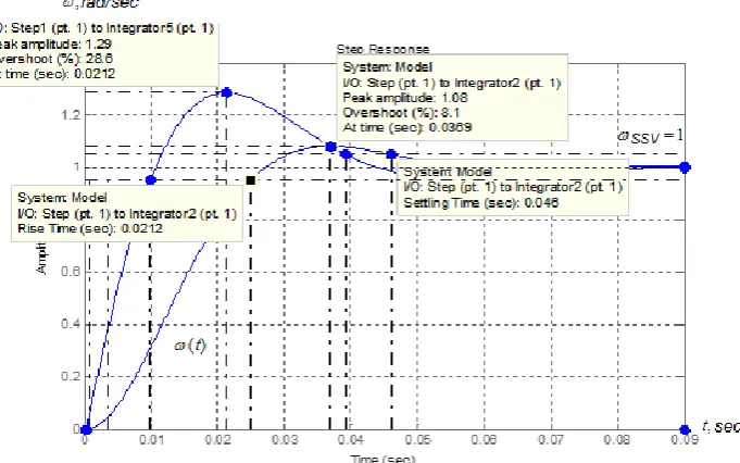
Transients simulation results in the speed loop, which is tuned on symmetrical optimum (with and without input filter) for step input signal UREF 1 (V) working-off, are shown as transient characteristic in fig. 10.
Dynamic quality factors of closed speed loop with input filter are listed in table 3.
Table 3. Dynamic quality factors of closed speed loop with input filter
Factors
Without filter With filter
Expect ed
Obtaine d
Expe cted
Obtai ned
,% 28.6 28.6 8.1 8.1
5 RISE,
t p.u 0.0103 0.0105 0.023 0.023
5 TR,
t p.u. 0.0314 0.036 0.033 0.046
ω bw
m
,p.u. 187.5 183 141.2 124
ω bw
ph
,p.u. 165.7 162 101.7 103
( )
t
Figure 10.Transient characteristics of speed loop that is tuned on symmetrical optimum
Conclusions and outlines
It has been found that application of variable frequency induction motor drive for flame reactor feed screw allows to provide dynamic quality factors comparable to the ones of DC electric drive based on shunt wound DC motor.
Analysis of dynamic quality factors of main loops of variable frequency induction motor drive system shows that the simulation factors are close to the expected ones. Minor error between them is caused by calculation simplifications during loop optimization. It should be noticed that transients quality factors in speed loop with input filter are better than without it.
Further studies of the flame reactor feeding system will be about determining the influence of the temperature and other environmental factors on performance of the electric drive, as well as their account in the control process.
References
[1] I. S. Vislov “A Batch Feeder for Inhomogeneous Bulk Materials” [et al.] //IOP Conference Series: Materials Science and Engineering. — 2016. —Vol. 124 : Mechanical Engineering, Automation and Control Systems (MEACS2015). — [012033, 5 p.]. — Title screen. — Free access via internet: http://dx.doi.org/10.1088/1757-899X/124/1/012033
[2] Popenda, A., Rusek, A.”The mathematical model and selected transient states of main drive for polymerization reactor taking the working parameters of reactor chamber under consideration” (Article) [Model matematyczny i wybrane stany nieustalone głównego napȩdu reaktora polimeryzacji przy uwzglȩdnieniu parametrów pracy komory mieszalnika] //Przeglad Elektrotechniczny. — 2008. —Vol. 84: Issue 5, Pages 84-87
[3] Brendakov V. N., Dementyev Yu. N., Kladiev S. N., Pischulin V. P.: Temperature control system of barrel rotating furnace for producing uranium oxides.¬¬¬– Tomsk: Bulletin of the Tomsk Polytechnic University, Vol.310. №1., 2007. – p. 186-190 (in Russian)
[4] Boyko S. V., Dementyev Yu. N., Kladiev S. N.: Variable frequency induction motor electric drive of feeding screw of flame reactor.– Izvestiya Vysshikh Uchebnykh Zavedenii, №6., 2009–p. 69-73 (in Russian)
[5] Shreyner R. T. Mathematical simulation of ac electric drives with semiconductor frequency converters.– Ekaterinburg: URO RAN, 2000.–654 p. (in Russian)
[6] Udut L. S., Maltseva O. P., Koyain N. V.: Design, development and research of automated electric drives. Part 7. Theory of optimation of continuous multiloop control systems of electric drives: Textbook.–Tomsk: Publ. House of Tomsk Polytechnic University, 2007.–164 p. (in Russian) [7] Tuning method of PI controller of VSC-HVDC based on modulus and symmetrical optimum / Xu, K. , Xian, X., Cheng, J., Tao, F. // Dianli Xitong Baohu yu Kongzhi/Power System Protection and Control. — 2016. — Volume 44, Issue 2, 16 January 2016, Pages 122-127. [8] Field Oriented Control of Induction Motors Using
Symmetrical Optimum Method with Applications in Hybrid Electric Vehicles (Conference Paper)/ Pavuluri, V.K., Wang, X., Long, J., Zhuo, G., Lian, W. // 2015 IEEE Vehicle Power and Propulsion Conference, VPPC 2015 – Proceedings.
[9] The advanced automated hardware-software complex of control and management of functioning of the megapolises complicated heat-supplying systems. Yu. N. Dementyev ; A. B. Kritsky. In package: The 2nd International Conference on Industrial Engineering, Applications and Manufacturing (ICIEAM), 2016, May 19-20
[10] The automatic control system of fluorite decomposition. Kladiev S.N., Pishchulin V.P., Dementiev Y.N. . In package: 8th Korea-Russia International Symposium on Science and Technology Proceedings: KORUS 2004. sponsors: Tomsk Polytechnic University, University of
8 thermal decomposition. Kerbel B.M., Pishulin V.P., Dementiev Y.N., Kladiev S.N. In package: The 4th International Conference for Conveying and Handling of Particulate Solids Proceedings. eds. H. Kalman and J. Gyenis. 2003. 2.38-2.44 pp.
[14] Direct moment control in asynchronous electric drive. Lavrentjev A.V., Dementjev J.N. In package: Modern Techniques and Technology MTT' 2001 proceedings of the 7th International Scientific and Practical Conference of Students, Post-graduates and Young Scientists. Tomsk Polytechnic University. 2001. 111-112 pp.