MAC Layer Design for Network-Enabled Visible Light
Communication Systems Compliant with IEEE 802.15.7
Trio Adiono
1,*, Syifaul Fuada
2, Muhamad Luthfi
3,
Rosmianto Aji Saputro
41,2 University Center of Excellence on Microelectronics Institut Teknologi Bandung, IC Design laboratory, PAU building 4th
floor, Jln. Tamansari No. 126, Kampus ITB, Bandung city (40132), West Java, Indonesia
3,4 Achmad Bakrie building (LABTEK VIII) 3rd floor, Electrical Engineering Department School of Electrical Engineering and Informatics Institut Teknologi Bandung, Jln. Ganesha No. 10, Kampus ITB, Bandung city (40116), West Java, Indonesia
Abstract
The design and implementation of medium access control (MAC) layer for network-enabled visible light communication (VLC) system is presented in this paper. The point-to-point link was chosen because of its simple in configuration as well as implementation. Whereas the FPGA Zybo Zynq-7000 is employed for prototyping the hardware of VLC system because of it serve a Linux operating system (OS), i.e. Xillinux. Our MAC layer has been realized in Python programming and running above the Zynq-7000 processor. The designed MAC Layer is adapted from IEEE 802.15.7 standard, specifically for delivering and receiving the MAC frames from the coordinator to the device or vice versa, wrapping the IP packets and unwrapping the MAC Frames with MAC headers and trailers, and performing the error detection in which the cyclic redundant check 16 (CRC-16) was selected. According to the functionality test, our proposed VLC system can perform to send the multimedia contents (video and image) as well as data packet for internet accessing purpose like a wireless fidelity (Wi-Fi) connectivity. Thus, it can be concluded that the implemented MAC layer has met the functionality specifications referred to the IEEE 802.15.7 standard. We also provide the Pseudo-code of designed MAC layer and its Python script (source-code) implementation that can be found in the Appendix section.
Keywords: Medium-access control (MAC), Visible light communication (VLC), TCP/IP
Received on 12 August 2017, accepted on 07 September 2017, published on 04 October 2017
Copyright © 2017 Trio Adionoet al., licensed to EAI. This is an open access article distributed under the terms of the Creative Commons Attribution licence (http://creativecommons.org/licenses/by/3.0/), which permits unlimited use, distribution and reproduction in any medium so long as the original work is properly cited.
doi: 10.4108/eai.4-10-2017.153163
1. Introduction
Recently, the visible light communication (VLC) is being developed to be proposed as an alternative to wireless communications. The VLC can substitute the role of long-range radio frequency (RF) because it can’t reach a very-closed area [1]. Moreover, the VLC is harmless for human skin health, when the other optical wireless communication technologies: Infra-Red (IR) and Ultra-Violet (UV) have the higher health risks. Since the lighting infrastructure of residential homes has already available, thus the VLC is easier and cheaper in terms of the implementation factor compared to the RF that require a specific base station [2].
*Corresponding author. Email:[email protected]/[email protected]
lighting infrastructure. This current technology called as light fidelity (Li-Fi) [4].
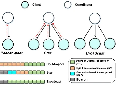
The Li-Fi system is a concatenation of the certain hardware and software components that work together to perform network-enabled functions with the visible light medium that contains physical (PHY) layer and medium access control (MAC) layer in which the PHY/MAC protocol has been released by the IEEE standard, namely 802.15.7 [5]. The MAC layer serves to set the communication flow of the developed system, thus it will possible to set the data exchanging with various schemes such as depicted in Figure 1. There are three link topologies referred to IEEE 802.15.7,
i.e. 1) peer-to-peer (P2P), this topology contains two devices, one as a coordinator and the other device as a client in which both of them communicate in two ways (bidirectional):
downlink, from the coordinator to the client, and uplink acts a vice-versa. The implementation of P2P can be done by half-duplex mode: downlink and uplink are worked alternately (similar to the mechanism of handheld transceiver radio/HT) as well as full-duplex mode (similar to the modern phone mechanism, including a smartphone).
Next is a star topology that similar to P2P topology, but used more than one clients in the optical network. In this topology, the coordinator can communicate with all clients and functioned as the central controller in an optical network communication [6].
The third topology is the broadcast that has similarity to the star topology but a one-way link only: from the coordinator to many clients (unidirectional). In this topology, each client in the optical network is received the transmitted data. This topology can be chosen if the VLC system intends for a broadcasting scheme, such as promotion media that applied in the modern market, data showers application in the conference halls area, etc.
Figure 1. Network topologies defined in IEEE 802.15.7 standard and its example the frame structure usage in
different topologies, reproduced from [7]
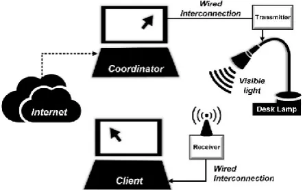
In this paper, we present the MAC layer design for network-enabled indoor VLC implementation to give facility on data exchange the “transmission control protocol-internet protocol” (TCP/IP) packets. In this work, we used P2P topology as illustrated in Figure 2. The P2P consists of two nodes yang that can communicate/data exchange among others data in which if one of the nodes connected to the internet (as an example), then another node will be able to access the internet also through a network link. The P2P topology was chosen with the reason of simple mechanism and easy realization because of it has only one device and one coordinator. While the MAC layer with star topology is too hard in design and also its implementation, even to this time, there are many challenges to develop it. It occurs because each client in the optical network is communicating in the bidirectional mode as well as all of them have activated at the same time [8].
Figure 2. Point-to-point topology that consists of two nodes and address setting (Internet protocol, MAC,
and domain name server)
We designed the overall VLC system based on Field-Processor-Gate-Arrays (FPGA) instead of general microcontroller usability to ensure that the wireless network connection is relatively high-speed. For prototyping purpose, the Zybo Zynq-7000 development board was chosen because of its complete offered features that include the various peripherals like Ethernet, universal serial bus (USB), general purpose input/output (GPIO), video graphics array (VGA), and universal asynchronous receiver-transmitter (UART). Furthermore, the Zybo Zynq-7000 supports a Linux operating system (OS) where one of them is Xillinux. In this work, the MAC layer has been realized in Python script that written by Xillinux. In another word, the MAC layer software is proceed on ARM-based processor- as software system-on-chip (S/W SoC), thus we don’t need a complicated hardware system-on-chip (H/W SoC) implementation in FPGA and the system test, like modelSIM simulation is not required also.
supports, flicker mitigation supports, association and disassociation of client device supports, etc. [9]. G.J. Blinowski described the risk occurs on PHY-level security from possible attacks (data snooping, signal jamming, and data modification) and also briefly analyze the MAC-level security mechanism [10]. N-T. Le and Y.M. Jang proposed the enhancement of MAC layer of IEEE 802.15.7 for VLC broadcast service [11]. B. Tomas et al proposed the MAC model for vehicular VLC application [12]. Y. Jia presented the MAC layer implementation referred to IEEE 802.3 standard that supports full-duplex communication [13]. The other related topic is carried-out by H. Guo et al that implements MAC controller in H/W of FPGA [14]. Later, A. Musa, et al analyzed the IEEE 802.15.7 protocol focused on the contention-access period part [15]. P. Shams et al
explored comprehensive the MAC layer performance of IEEE 802.15.7 standard, involve several parameters: throughput, delay, power consumption, and its probability profile (collision, transmission, access and packet discard) [16].
The main difference between this works to among mentioned papers is contents substance, especially in area focus. We designed the MAC layer only to perform the following task 1) delivery and receiving of MAC frames from the host to the client or vice versa; 2) undertake the process of IP packet wrapping and unwrapping the MAC frame with MAC header and trailer referred to the IEEE 802.15.7 standard; 3) exercise the error checker. Whereas the method for evaluating its system performance, we only used the functional test data whether the designed MAC layer can execute well the assigned tasks or not. It means without more comprehensive measurements like throughput, delay, power consumption, etc. The study that nearly corresponding with this work has been presented by V. Mariappan et al, they designed the PHY/MAC on Arduino microcontroller to enable internet infrastructure connectivity utilizing VLC [17]. However, it is lack of the discussion of achieved data from the performance test.
This paper is organized as follows: In Section 2, we discuss the previous work to deliver the readers in understanding the whole VLC system and provide an illustration for the next section, then introduce the designed MAC protocol referred from IEEE 802.15.7 and describe how it performs. Section 3 is devoted the MAC functionality test and presents the VLC demonstration. Finally, Section 4 concludes our work.
2. Methodology
2.1. Overview of Proposed System
Figure 3 conceives the typical application of our VLC platform referred to Figure 2 that dedicated for personal area network in indoor environment. The aim of the proposed system is to provide a free-access to the users in data sharing, thus they can distribute everything related to the multimedia
contents like video, image, audio, and texts. Further, the internet browsing (both for downlink and uplink purpose) can be performed. Our VLC system is composed of three main parts: i) coordinator (host), ii) client (user), and visible light channel. In this work, the coordinator is not bypassed directly to the router but being employed the personal computer (PC) that attached to the internet. Therefore, it has a role as internet-connected host PC.
Figure 3. The primary application of proposed VLC system for a short-range personal area network
In order to appropriate with the working principle of the proposed system as shown in Figure 3, we develop the entirety system that divided into two sections, just like depicted in Figure 4, that is 1) digital section consists of MAC layer that accommodates the communication path setting, the packaging of sent data, and un-packaging of received data. Then the digital block performed to convert the bit streams into analog signals or vice-versa. 2) Analog section functioned as an analog signal processing consists of switch LED driver [18], trans-impedance amplifier (TIA) [19], pre-amplifier (pre-Amp), Op-Amp comparator, and a transistor switch. The main topic to be completed in this paper is MAC layer design, it is pointed-out in blue-colored block.
Figure 4. Block diagram of the overall VLC system
In this work, the PHY layer development is not focused to comply the IEEE 802.15.7 standard, thus a UART peripheral was chosen with the reason of its simple implementation and no synchronization required [20]. To generate the UART communication, we used the Vivado 201.1. For connecting the PC to our system (via Zybo board), we used the Ethernet wire. There is no need to manually configure because the Ethernet connection has been already activated in Zybo. In this work, the on-off keying (OOK) was employed as the modulation.
2.1. MAC Layer Design
In line with the brief explanation in Section 1 about the targeted functionalities, following are the designed MAC layer in the data frame form, which consists of three components, i.e. i) MHR or MAC header that consist of frame control, sequence number, address information, and security related information; ii) MSDU or MAC service data unit that consist of frame payload; the end component is iii) MFR or MAC footer that consist of frame check sequence (FCS). The structure of designed MAC frame referred to the IEEE 802.15.7 standard [5]. Figure 6 shows the structure of implemented MAC framework in which each field comprises the several components, namely frame control field, sequence number, destination VLC personal area network (VPAN) identifier field, destination address field, source VPAN identifier field, source address field, auxiliary security header field, frame payload field, and FCS field.
Figure 6. MAC frame structure that used this work, reproduced from [5]
The frame control field has a length of two octets and comprises one of the frame type information as well as the addressing field. Below the rule of MAC frame setting that carried-out in this work.
(i) Frame version: set to 0b00 (ii) Reserved: set to 0b00000
(iii) Frame type: selected to 0b01 because only MAC frame data type is required
(iv) Security enabled: designed MAC layer without protection, set to 0b0.
(v) Frame pending: set to 0b0 (vi) ACK request: set to 0b0
(vii) Destination and Source address: designed MAC layer with source address and destination address containing 16-bit short address to prepare system if multiple user developments is being held. Thus, set to 0b01.
The sequence number field has a length of 1 octet and specify the sequence number data. In this work, we used only for 1 client (user) then the sequence number is set to 0b0.
The destination VPAN field has a length of 2 octets and set with a unique value, that is 0xFF00, to be sent to the intended recipient frame. This field is only used if the destination addressing mode is set to 0b10 and 0b11. While the
destination address field is set with a unique value of 0x0101. The source VPAN identifier field has a length of 2 octet and specifies the unique VPAN identifier of the sender frame, in this work is set to 0x00FF. This field is only used if the source addressing mode is not set to “0”. The source address field has a length of 2 octets or 8 octets and specifies the value of the source addressing mode subfield on frame control field. This field is only used if the source addressing mode subfield is set with 0b10 or 0b11. In this work, we set with a unique value that is 0x1010.
The auxiliary security header field is used to specify the information required for security and also the security enabled to “1”. In this work, we don’t used this setting, so this
auxiliary security header field is set to 0b01. Whereas the
frame payload field has a variable length and holds data information from the open systems interconnection (OSI) layer which is over of the MAC layer. The last field is FCS field that has a 2 octets of length and comprises error checker that is used for error detection of the MAC frame.
2.2 Cyclic Redundant Check (CRC)
The CRC-16 chosen to detect the erroneous packets from the MAC layer protocols. The CRC code uses 16 redundant bits [21] and has a length 2 octets, it can be solved by using standard polynomials generator as expressed in Equation 1.
𝐺16(𝑥) = 𝑥16+ 𝑥12+ 𝑥5+ 1 (1)
The CRC code can be calculated by algorithm below:
Take M(x) = boxk-1 + b1 xk-2 + … + bk-2x + bk-1 became a polynomial that represented the bit in which its checksum will be calculated.
Multiply the M(x) with x1
Divide the x16. M(x) modulo 2 with the polynomial generator G16(x), to obtain the reminder polynomial, R(x) = rox15 + r1 x14 + … + r14x + r15
CRC field is filled with the coefficients from the reminder polynomial,R(x)
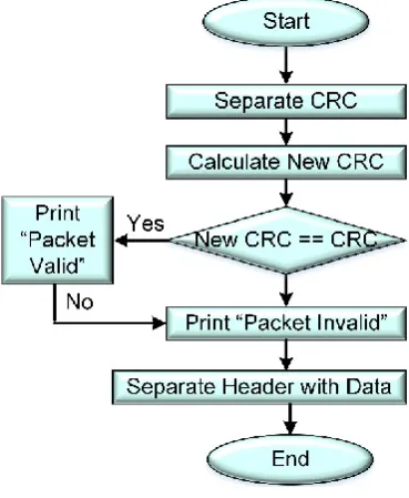
2.3 MAC Flowcharts
systems only. The wrapping process is to combine data sent with MHR and MFR, while the unwrapping process does the opposite process. The detecting an error using CRC-16 is done using the library that has been provided in Xillinux. Figure 7 is a flowchart of sending data from the host to the client. The data delivery starts from the socket declaration. Afterwards, the data (IP packet data) is obtained and then sent to the serial port. The process is repeated with the while loop true. Whereas Figure 8 is a flowchart of receiving data from the client to the host. The reception begins with the creation of a serial port handler then receives the data (MAC frame data) and finally sent to the socket. The process is repeated with the while loop true.
Figure 7. Flowchart for delivery the MAC frame
Figure 8. Flowchart for receiving the MAC frame
Figure 9 is a flowchart for wrapping process that has been clearly done after the host and the client receives the IP packets. The IP packets are wrapped with the created headers as well as trailers, where the header consists of frame control, addressing field, auxiliary address field and then the footer is the result of the CRC-16 calculations that computed by Equation 1.
Figure 9. Flowchart for wrapping the IP packet
Figure 10. Flowchart for unwrapping the MAC frame and error detection using CRC-16
3. Results and Analysis
3.1. MAC Layer Implementation
In summary of the subsection 2.3, the system is built from the main function. The IP packet is retrieved from the socket then wrapped it into the MAC frame. Afterwards, it is sent through the serials port. Upon reaching the destination target (both for the host or the client), the unwrapping proses of the MAC frame is done. Thus, it becomes an IP packet. The error detection also being done simultaneously. The next process, the IP packet is inserted to the upper layer via socket.
Table 1 is the “program name” in Python script of
following parts: i) the main function
(Packet_transfer_pure.py), ii) specific process of wrapping the IP packets (MACWrap) and iii) unwrapping the MAC frame (MACUnwrap). We utilized the available library in Xillinux to realize iv) the CRC-16 calculation for error checker and written in python script. It has been done by following setting: setup.py then replaced by CRC16.py.
Then to run the implemented scripts in Xillinux, we must call it by the command prompt or cmd.exe.
Below the MAC source code implementation in the form of Pseudo-code. Whereas the realized Python language can be shown in Appendix.
MAC layer implementation in Pseudocode Function MACWrap(IPPacket):
Set FrameControl Set Addressing Field Set AuxSecHeader Field Header =
Concatenation(FrameControl,AddressingField, AuxSecHeaderField)
MACFrameTemp =
Concatenation(Header,IP Packet)
Footer = CalculateCRC16(MacFrameTemp) MacFrame = Concatenation(MACFrameTemp, Footer)
return (MACFrame) Function MACUnwrap(MACFrame):
MACFrameTemp,OldFooter = Decatenate(MACFrame)
NewFooter = CalculateCRC16(MACFrameTemp) If (OldFooter == NewFooter)
Error Detection Header,IPPacket = Decatenate(MACFrameTemp)
return (IPPacket)
Begin Main Program Initiate Socket
Initiate Serial Port Handler
While True:
#Transmitter
Receive IP Packet From Socket MACWrap(IPPacket)
Sent to Serial
#Receiver
Receive MAC Frame From Serial MACUnwrap(MACFrame)
Sent to Socket end
End Main Program
3.2. Functional Tests
In order to meet the qualifies of VLC demonstration, in this work, the IP address and MAC setting are an arbitrary as long as its consistent usage across in all components (as illustrated in Figure 2). Whereas the domain name servers used the Google’s public, namely 8.8.8.8 in which it offers certain performance advantages [22].
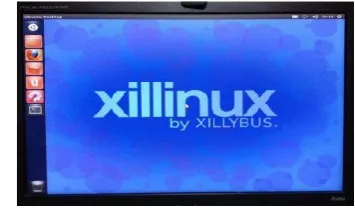
The first step that should be carried-out is prepare the OS, including: booting up, running the Python script, and loading the standard GUI interface as visualized in Figure 11.
Figure 11. Xillinux display on the PC monitor
In order to verify the designed MAC layer, we integrate the whole system of VLC (Figure 5). We used three PCs: 1) to display the received data packets (PC Client–1), 2) to see the display of sent data packets (PC Host), 3) to view the received files (PC Client–2) that appear from the photograph. The VGA cable and LAN wire from the PC Client–2 are connected to the VGA- and Ethernet-port of Zybo board receiver respectively, while the PC Host does the same step but linked to the Zybo board transmitter. The phosphorus white LED is installed in the desk-lamp and the Zybo as well as the analog circuits are packed in the specific box then faced directly to the LED (line-of-sight optical channel). In this experiment, we don’t incorporate the IR for uplink. Thus, we connect the client to the host directly without optics (by wire).
Figure 12. A photograph of MAC layer functional test
When the Xillinux OS has been run-up, subsequently the functionality test for the designed MAC layer can be observed as visualized in Figure 12. As stated in Section 1,
Analog Receiver VGA PC Host
LED Driver PC Client - 1
9 Watt
the examination for the designed MAC layer is only cover three tasks: delivery and reception of MAC frame, wrapping the IP packet and unwrapping the MAC frame, and error detection utilizes CRC-16. The test case is to check-out whether the MAC layer can perform well as expected or not.
In this work, the testing is done by “ping” at the client side in which it is addressed to 192.168.137.20, precisely as depicted in the network setting (pointed-out in Figure 2). The “ping” cab is entirely done as visualized in Figure 13.
Figure 13. The command prompt in pinging IP address
From the test results as visualized in Figure 14 and Figure 15, it can be shown that the designed MAC layer is successfully capable of delivery MAC packets from the PC Host to the PC Client and vice versa evidenced by the words of the request process “receiving packet 74 bytes” later “sending serial…” “receiving serial 74 bytes” later “consuming packet…” sequentially. The number 74 of bytes indicate the packet size in which the value is random.
Figure 14. A photograph of the PC monitor connected to the Host (PC Host)
Figure 15. A photograph of the PC monitor connected to the Client (PC Client – 1)
The next test is wrapping and unwrapping mechanism that also performed by “Ping”. Figure 16 and Figure 17 depict that the process is already successful. The 103 bytes also
indicates the packet size in which its value depends on received packet. It can be shown from Figure 17(a), there is a frame with data packet which contain the packet contents (random characters = abcdefghijk … fghif), the header
00100022FF0000FF010110100 and the footer F092. On the next line, the IP packet successfully unwrapped evidenced by the absence of the header as well as the footer as marked in a red-line as shown in Figure 17(b). The process is done at many times.
Figure 16. A photograph of the PC monitor connected to the Host (PC Client – 1)
(a)
(b)
Figure 17. A photograph of the PC monitor connected to the Client (PC Host)
The last examination is the CRC-16 acts as error checker in which there are two conditions of testing: when there is error and no error occur. The method is to print the IP packets and MAC packets at the command prompt. Thus, it can be shown whether the CRC-16 is running correctly.
(a)
Begin
(b)
Figure 18. A photograph of: (a) the PC monitor connected to the Client (PC Host); (b) command
prompt the error is existed
Figure 18(a) visualizes the results when there is an error in delivering or receiving MAC Frame, the order of “packet valid” statements is initial and ending while the statement “packet invalid” is located in the center of the screenshot. Figure 18(b) visualizes the results viewed from the command prompt, there is a reply at the beginning and ending in which the request time-out is located at the center. For two evidences, it can be concluded that the error detection works well when there is an error. In this case, two packets is not received from four sent packets (50% loss).
Figure 19. A photograph of command prompt when there is not error occur
Figure 19 visualizes the obtained results, if there is no error occurs during the process (all statements issued by “packet valid”), the “ping” will manage to get a reply from the four requests. It can be concluded that the error detection using CRC-16 also works well when there is no error. In this
case, all of four packets is received from four sent packets (0% loss).
3.3. Demonstration
Figure 20 looks the experimental setup in which the arrangement is same with the setting as shows in Figure 12. When the functional tasks of the designed MAC layer are carefully tested, actually the VLC system can be demonstrated immediately to share the multimedia contents like video, audio, texts, or image. Due to the space limitations of the paper’s illustration, we zoomed out (the orientation center is marked in red dotted-line) the photo and specifically brought to Figure 12.
Figure 21(a) visualized the successful image transfer without compresses and extraction, it means that the received file is identical with the transmitted. Figure 21(b) evidences the fruitfulness of video streaming without buffer occurs, it means that the video can stream in a real-time. To access the video, we should enter the URL in web browser address bar just like standard structure, such as:
http://192[dot]168[dot]1[dot]1/stream[dot]mp4. Then the
internet browsing via LED bulb also has been demonstrated with bit-rate speed of 11 kbps only, as depicted in Figure 20(c). It is caused by the limitation of AFE bandwidth in which we do not discuss it. The overall VLC demo proves that the designed MAC layer truly works well as predicted.
Figure 20. Experimental setup
(a) (b) (c)
Figure 21. Successfully demonstration of: (a) an image transfer with 512 pixels@500 kb, taken from [23]; (b) a real-time video streaming with resolution of 360p or 640 x 360, taken from [24]; internet access (browsing)
PC Client - 2 PC Client - 1
PC Host
LED Analog Receiver
FPGA
Driver FPGA
Received image
Video
Table 1.The functions and descriptions of the designed MAC layer in Python script
Function name Description Input (type) Output (type)
MACWrap
• Formation of frame control formation • Formation of frame addressing field • Formation of MHR (MAC header)
• Calculation of MFR (MAC footer) by using CRC-16 that utilizes available libraries
• MSDU concatenation with MHR and MFR
MSDU (String) MACFrame (String)
MACUnwrap
• Release of MHR
• MFR retrieval from incoming frame • Calculation of MFR by using CRC-16
• Comparison of MFR before sent frame sent and after sent frame • Issuing error detection status
MACFrame
(String) MSDU (String)
CRC16.py Perform the CRC-16 calculation String String
Figure 5. The position of the designed MAC layer within the whole VLC system
4. Conclusion
In this paper, the designed MAC layer for network-enabled VLC has been successfully tested and met the functionality specifications referring the IEEE 802.15.7 standard such as support the generate network between the transmitter to the receiver (delivery-reception as well as wrapping-unwarpping the IP/MAC packets) and error detection (we used the CRC-16). The evaluation other than “ping” cab, also has been done by share the multimedia contents (video with 360p and small pixels image) and low-speed internet browsing. The MAC layer is programmed on the processing system using a FPGA Zybo Zynq-7000. In other words, it is implemented as S/W SoC.
Appendix A. MAC Layer Implementation
in Python Programming
CRC-16 implementation in Python script #CRC16.py
from ctypes import c_ushort
class CRC16(object): crc16_tab = []
# The CRC's are computed using polynomials. Here is the most used
# coefficient for CRC16
crc16_constant = 0xA001 # 40961
def __init__(self, modbus_flag=False): # initialize the precalculated tables if not len(self.crc16_tab):
self.init_crc16()
self.mdflag = bool(modbus_flag)
def calculate(self, input_data=None): try:
is_string = isinstance(input_data, str) is_bytes = isinstance(input_data, bytes)
if not is_string and not is_bytes: raise Exception("Please provide a string or a byte sequence " "as argument for calculation.")
crcValue = 0x0000 if not self.mdflag else 0xffff
for c in input_data:
d = ord(c) if is_string else c tmp = crcValue ^ d
crcValue = rotated ^
int(self.crc16_tab[(tmp & 0x00ff)], 0)
return crcValue except Exception as e:
print("EXCEPTION(calculate): {}".format(e))
def init_crc16(self):
'''The algorithm uses tables with precalculated values'''
for i in range(0, 256): crc = c_ushort(i).value for j in range(0, 8):
if (crc & 0x0001):
crc = c_ushort(crc >> 1).value ^ self.crc16_constant
else:
crc = c_ushort(crc >> 1).value self.crc16_tab.append(hex(crc))
Overall MAC layer implementation in Python script import serial
import socket
from PyCRC.CRC16 import CRC16
HOST = 'eth0'
def MACWrap(MSDU): FrameVersion = ['0'] Reserved = ['0'] FrameType = ['1'] SecurityEnabled = ['0'] FramePending = ['0'] AckRequest = ['0'] DestAddressMode = ['2'] SourceAddressMode = ['2']
DestVPANIdentField = ['F','F','0','0'] SourceVPANIdentField =
['0','0','F','F']
DestAddress = ['0','1','0','1'] SourceAddress = ['1','0','1','0'] AuxSecHeaderField = ['0']
FrameControl = FrameVersion + Reserved + FrameType + SecurityEnabled + FramePending + AckRequest + DestAddressMode +
SourceAddressMode
AddressingField = DestVPANIdentField + SourceVPANIdentField + DestAddress +
SourceAddress
MHR_list = FrameControl + AddressingField + AuxSecHeaderField
MHR = ''.join(MHR_list) MHRMSDU = MHR + MSDU MFR = str('%02x' % CRC16().calculate(MHRMSDU))
MACFrame = MHRMSDU + MFR
return (MACFrame)
def MACUnwrap(MACFrame):
MACFrame.split() #calculate CRC
lenMHRMSDU = len(MACFrame) - 4 Temp1 = MACFrame
Temp2 = MACFrame
MFR_list = MACFrame[lenMHRMSDU:] MFR = ''.join(MFR_list)
MHRMSDU_list = MACFrame[:lenMHRMSDU] MHRMSDU = ''.join(MHRMSDU_list)
MFR_Calc = str('%02x' % CRC16().calculate(MHRMSDU_list))
#if CRC before send and after receive is same, packet is valid, otherwise invalid
if (MFR_Calc == MFR):
print("Packet Valid") else:
print("Packet Invalid")
#proceed unwrapping packet MHRMSDU.split()
MSDU_list = MHRMSDU[25:] MSDU = ''.join(MSDU_list) return (MSDU)
# Pakcet_transfer_pure.py
s = socket.socket(socket.AF_PACKET, socket.SOCK_RAW, socket.ntohs(0x0800)) s.bind((HOST, 0))
s.setblocking(0)
# Create Serial Port handler
ser = serial.Serial('/dev/ttyPS1', 115200) print(ser.name)
# buffer from serial port serialBuffer = ""
lengths = 0
while True: try:
# receive a packet # hexa is the tcp packet hexa, ip = s.recvfrom(65536) hexa_ready = MACWrap(hexa)
# If any, send it to serial port lengths = len(hexa_ready)
#print hexa_ready if(lengths > 0):
print('Receiving packet ' + str(lengths) + ' bytes')
# Send 16-bit length to serial port byte1 = lengths & 0xFF byte2 = (lengths >> 2) & 0xFF
ser.write(chr(byte1)) ser.write(chr(byte2))
# Send the rest of data print('Sending serial...') for data in hexa_ready: ser.write(data)
except: pass
# check any incoming data in serial port # print('Checking incoming serial data..')
if(ser.inWaiting() > 0):
lengths = ord(ser.read()) lengths = lengths | (ord(ser.read()) << 2)
serialBuffer = ""
print('Receving serial ' + str(lengths) + ' bytes')
while(lengths):
serialBuffer += ser.read() lengths -= 1
# send the packet
print('Consuming packet...')
Appendix B. Abbreviations
AFE Analog front-end CRC Cyclic redundant check DNS Domain name servers FCS Frame check sequence FPGA Field processor gate arrays GPIO General-purpose input/output GUI Graphical user interface H/W Hardware
IP Internet protocol IR Infrared communication LED light emitting diode Li-Fi Light fidelity
MAC Medium access control MFR MAC footer
MHR MAC header
MSDU MAC service data unit OOK On-off keying
OS Operating system
OSI Open systems interconnection P2P Point-to-point communication PC Personal computer
PD photodiode PHY Physical layer
RF Radio frequency communication S/W Software
SoC System-on-chip
TCP Transmission control protocol TIA Trans-impedance amplifier
UART Universal asynchronous receiver-transmitter USB Universal serial bus
UV Ultraviolet communication VGA Video graphics array
VLC Visible light communications VPAN VLC personal area network Wi-Fi Wireless fidelity
Acknowledgements.
This research is one part of the big project entitled “Machine-to-machine Communication (M2M) based on Visible Light Communication (VLC)” was supported by Kerja sama Luar Negeri (KLN) program funded by the Ministry of Research, Technology and Higher Education of the Republic Indonesia (Kemenristekdikti) with Number of grant: 009/SP2H/LT/DRPM/IV/2017.
We would like to grateful to our friend Muhammad Ghifari who help us indirectly also to Mrs. Aciek Ida Wuryandari. This work has correlated with the other papers and the readers can enjoy to read it, kindly follow at [25-31].
Authors Contribution.
T.A. proposed the concept, supported for funding, fully managed and supervised the project; M.L. designed and realized the MAC layer in Python programming and drafted the reports; R.A.S constructed the H/W- & S/W-SoC and optical wireless network; S.F. helped to develop the AFE transceiver; M.L, R.A.S, and S.F. carried out the VLC demo; M.L analyzed the data of functional tests; S.F. delineated all of the pictures in the manuscript and contributed to the writing of the manuscript.
References
[1] Fuada, S. (2017). Design and Implementation of Analog Front-End Transceiver Module for Visible Light Communication System. Master Thesis, Department of Electrical Engineering, School of Electrical Engineering and Informatics (SEEI), Institut Teknologi Bandung, Bandung, Indonesia.
[2] Jovicic, A., J. Li, and T. Richardson (2013) Visible light communication: opportunities, challenges and the path to market,” IEEE Commun. Mag., 51(12): 26–32.
[3] Hass, H., Wireless data from every light bulb (2011). In TEDx forum. The video is available at:
http://www.ted.com/talks/harald_haas_wireless_data_from _every_light_bulb.html.
[4] Haas, H., L. Yin, Y. Wang, and C. Chen (2016) What is LiFi?. J. of Lightwave Technology 34(6): 1533-1544. [5] IEEE Computer Society, “IEEE Standard for Local and
metropolitan area networks – Part 15.7,” Short-Range Wireless Optical Communication Using Visible Light, New York: IEEE.2011.
[6] Uysal, M., et al., (2017) IEEE 802.15.7: Visible Light Communication Standard. Ghassemlooy, G., L.N. Alves, S. Zvanovec, M-A. Khalighi. [ed.], Visible Light Communications Theory and Applications (London: CRC Press), ch 5.
[7] Pathak, P.H., X. Feng, P. Hu, and P. Mohapatra, (2015) Visible Light Communication, Networking and Sensing: A Survey, Potential and Challenges. IEEE Commun. Surveys and Tutorials 17(4): 2047-2077.
[8] Fuada, S., (2017) Kajian Aspek Security pada Jaringan Informasi dan Komunikasi Berbasis Visible Light Communication. J. INFOTEL 9(1): 108-121. DOI:
10.20895/infotel.v9i3.288.
[9] Khan, L.U. (2017) Visible light communication: application, architecture, standardization and research challenges. Digital Commun. and Networks 3(2): 78-88. [10] Blinowski, G.J. (2016) Practical Aspects of Physical and
MAC Layer Security in Visible Light Communication Systems. Int. J. of Electronics and Telecomunications 62(1): 7-13.
[11] Le, N-T., Y.M. Jang (2013) Broadcasting MAC Protocol for IEEE 802.15.7 Visible Light Communication. In Proc. of the 5th Int. Conf. on Ubiquitous, Da Nang – Vietnam, July 2-5, 2013 (USA: IEEE), 667-671.
[12] Tomas, B., H-M. Tsai, M. Boban (2014) Simulating Vehicular Visible Light Communication: Physical Radio and MAC Modeling. In Proc. of IEEE Vehicular Networking Conf, Paderborn-Germany, December 3-5, 2014 (USA: IEEE), 228-231.
[13] Jia, Y., M. Zhang, Y. Huang, and Y. Zhang (2014) Design of an FPGA based visible light communication system. In Proc. of the 12th Int. Conf. on Optical Internet, Jeju-South Korea, August 27-29, 2014 (USA: IEEE), 1 - 2.
[14] Guo, H., et al. (2017) FPGA Implementation of VLC Communication Technology. In Proc. of Int. Conf. on Adv. Information Networking and Applications Workshops, Taipei-Taiwan, March 27-29, 2017 (USA: IEEE), 586-590. [15] Musa, A., M. D. Baba, and M. A. Mansor (2013) Analysis
of the Contention Access Period (CAP) Model for the IEEE 802.15.7 Visible Light Communication. Int. J. of Computer and Communication Engineering2(5): 621-624.
communication standard. Trans. on Emerging Telecommunications Technologies. DOI: 10.1002/ett.3015. [17] Mariappan, V., M. Lee, J. Cha. (2016) PHY/MAC Design to Enable Internet InfrastructureConnectivity on VLC. Int. J. of Engineering Research in Electronics and Communication Engineering (IJERECE) 3(8): 189-193. [18] Adiono, T., S. Fuada, A.P. Putra, and Y. Aska (2016).
Desain Awal Analog Front-End Optical Transceiver untuk aplikasi Visible Light Communication. J. Nasional Teknik Elektro dan Teknologi Informasi (JNTETI) 5(4): 319-327. DOI: 10.22146/jnteti.v5i4.280.
[19] Fuada, S., A.P. Putra, Y. Aska, and T. Adiono (2016) Trans-impedance Amplifier (TIA) Design for Visible Light Communication (VLC) using Commercially Available OP-AMP. In Proc. of the 3rd Int. Conf. on Information Tech.
Computer, and Electrical Engineering (ICITACEE). Semarang-Indonesia, October 19-21, 2016 (Semarang: Universitas Diponegoro), pp. 31-35. DOI:
10.1109/ICITACEE.2016.7892405.
[20] Song, Z., S. Peng, (2016) A Simple Implementation of Long Distance Visible Light Communication System. In Proc of ICMIC and ICOEE, 349-355.
[21] Tsimbalo, E., X. Fafoutis, R. J. Piechocki (2017) CRC Error Correction in IoT Applications. IEEE Transactions on Industrial Informatics 13(1): 361-369.
[22] Anonymous, Performance Benefits. Available at:
https://developers.google.com/speed/public-dns/docs/performance, Last updated: June 23, 2016. Accessed: October 7, 2017.
[23] Adiono, T., R. A. Saputro, M. Luthfi, S. Fuada, FPGA Implementation for Real-time File Transfer using Visible LightCommunications. Unpublished.
[24] Adiono, T., R. A. Saputro, M. Luthfi, S. Fuada, A Real-time Wireless Video Streaming based on VLC Technology using FPGA. Unpublished.
[25] Fuada, S. A.P. Putra, and T. Adiono (2017) Short-range Audio Transfer through 3 Watt White LED based on LOS Channels,” In Proc. Of Int. Conf. on Intellegent Signal Processing and Communication Systems (ISPACS), Xiamen-China, November 6-9, 2017 (China: Huaqiao University with IEEE).
[26] Fuada, S., T. Adiono (2017) Rancang Bangun Layer Fisik Visible Light Communication Pada Sistem Transmisi Audio. J. INFOTEL 9(3). August 2017. DOI:
10.20895/infotel.v9i3.288.
[27] Putra, A.P., S. Fuada, Y. Aska, and T. Adiono. (2016) System-on-Chip Architecture for High-Speed Data Acquisition in Visible Light Communication System. In Proc. of the IEEE Int. Symposium on Electronics and Smart Devices (ISESD), Bandung-Indonesia, October 29-30, 2016 (Bandung: Institut Teknologi Bandung), 63-67. DOI:
10.1109/ISESD.2016.7886693.
[28] Adiono, T., Y. Aska, S. Fuada, A.A. Purwita (2017) Design of an OFDM System for VLC with a Viterbi Decoder. IEIE Transactions on Smart Processing and Computing. [29] Adiono, T., Yulian Y. Aska, A.A. Purwita, S. Fuada, and
A.P. Putra. (2017) Modeling OFDM system with Viterbi Decoder Based Visible Light Communication” In Proc. of the Int. Conf. on Electronic, Information and Communication (ICEIC), Phuket-Thailand, January (Thailand: IEIE-ECTI Association, IEEE CES).
[30] Adiono, T., S. Fuada, and A. P. Putra. LED Driver Design for Indoor Lighting and Low-rate Data Transmission Purpose. Unpublished.
[31] Fuada, S., A.P. Putra, and T. Adiono, (2017) Analysis of Received Power Characteristics of Commercial
Photodiodes in Indoor LoS Channel Visible Light Communication. Int. J. of Advanced Computer Science and Applications (IJACSA) 8(7): 164-172 DOI:
![Figure 6. MAC frame structure that used this work, reproduced from [5]](https://thumb-us.123doks.com/thumbv2/123dok_us/8418097.1693120/4.595.47.295.433.535/figure-mac-frame-structure-used-work-reproduced.webp)