* Corresponding author at: Tel: +98 (61) 52343645; fax: +98 (61) 52341546 E-mail address: [email protected] ; [email protected] (A. Kargari)
Research Paper
Preparation of Poly(ether-6-block amide)/PVC Thin Film Composite Membrane for CO
2Separation: Effect of Top Layer Thickness and Operating Parameters
Iman Khalilinejad, Hamidreza Sanaeepur, Ali Kargari
*Membrane Processes Research Laboratory (MPRL), Department of Chemical Engineering, Amirkabir University of Technology (Tehran Polytechnic), Mahshahr Campus, Mahshahr, P.O. Box 415, Iran
HIGHLIGHTS
Thin film composite membranes of Pebax-1657 on a PVC ultrafiltration membrane support.
The effects of selective layer thickness, polymer concentration, and operating conditions.
Permeances of the gases increased in the TFCs compared to the neat Pebax membrane.
GRAPHICAL ABSTRACT
ARTICLE INFO ABSTRACT
Article history: Received 2014-10-10 Revised 2014-12-19 Accepted 2014-12-20 Available online 2014-12-21
Keywords: CO2 separation Pebax PVC
Thin film composite membrane Membrane thickness
In this work, novel thin film composite membranes (TFCs) of poly (ether-6-block amide) (Pebax-1657) on a polyvinyl chloride (PVC) ultrafiltration membrane as support were prepared using inclined coating method for CO2 separation.
Investigating the effects of top selective layer thickness formed by controlling the coating angle (15-60°) and polymer solution concentration (5-10 wt.%), and also, the effects of different operating pressure (2-10 bar) and temperature (25-50 °C) conditions were selected as challenging case study. Morphological considerations of the Pebax/PVC TFCs were evaluated by scanning electron microscopy (SEM) that revealed a defect-free thin selective layer of Pebax/PVC composite membrane. The single CO2, CH4 and N2 gases' permeance carried out using constant-volume/variable-pressure method. The results suggested
that the CO2 permeance, CO2/N2 and CO2/CH4 selectivity of the membranes increase upon pressure and decrease with
temperature increment. In addition, the permeations of CO2, CH4 and N2 increased respectively 16.7, 21 and 18% in
Pebax/PVC TFCs compared to the neat Pebax free stand membrane.
© 2015 MPRL. All rights reserved.
1. Introduction
Gas separations have always been one of the key processes in chemical engineering. Moreover, in the environmental and industrial points of view,
carbon dioxide (CO2) removal from gas streams is always useful for
I. Khalilinejad et al. / Journal of Membrane Science and Research 1 (2015) 124-129
membranes and cryogenic distillation used for the CO2 capture from gaseous
compounds [3–7]. Because of their fundamental engineering and economic advantages over competing separation technologies, membrane operations are now being explored for CO2 capture from power plant emissions and other
fossil fuel-based flue gas streams, since membranes do not require any phase transformation [8–10].
Membranes are low cost barriers for separating of gases, when high purity gas streams are not vital [8]. Many polymer membranes for gas separation have been studied due to their good properties such as ease of processability, good mechanical property, simplicity, high packing density and low energy requirements [11-17]. However, there are a number of challenging issues associated with the capture of CO2 from flue gases which
limit the use of polymer membranes for industrial applications like low permeance, low selectivities and high fabrication costs in some cases [2,5,9,18–21]. Two main parameters which determine the applicability of membranes for a specific separation are the permeability and selectivity. By developing proper materials along with minimizing the thickness of the separating layer, good selectivity as well as the high permeation rates could be obtained. Also the thinner the active separating layer results the lower costs in case of expensive polymers [22]. These are the reasons that the industrial gas separation polymeric membranes are generally fabricated as composite [22,23]. These membranes (see Fig. 1) are made as flat sheet or hollow fibre; have a thin, dense skin layer supported by a micro-porous layer that provides mechanical strength. The third layer is a thicker non-woven reinforcing fabric that provides for the main part of the mechanical backbone of the composite structure [22-25].
Fig. 1. A schematic of a thin film composite membrane [25].
Fig. 2. The chemical structure of Pebax-1657 [28].
Poly(ether block- amide) resin is one of the best known material under the trademark Pebax® which has offered excellent properties for CO
2
separating membranes. It is a thermoplastic elastomer combining linear chains of the hard polyamide (PA) segments that provide mechanical strength with interspacing of flexible polyether (PE) segments which offer high permeability due to greater chain mobility of the ether linkage. Different grades of Pebax have been prepared by varying the ether and amide compositions for gas separation applications [25-27]. In the present work, poly(amide-b-ethylene oxide) (with the commercial name of ‘Pebax® MH
1657’), which is composed of 40% aliphatic polyamide (PA6, nylon-6) and 60% poly(ethylene glycol) (PEG), was selected as the base polymer for membrane preparation. Fig. 2 shows chemical formula of the Pebax-1657 copolymer [28].
In this work, a new composite membrane with Pebax-1657 as the selective layer on a PVC porous support (Pebax-1657/PVC thin film composite) was fabricated via the inclined coating method and used for gas separation. Poly(vinyl chloride) (PVC) is selected to fabricate an ultrafiltration membrane support for the present thin film gas separation membrane because of its excellent physicochemical and mechanical properties and low cost [28,29]. Afterwards, the effects of film thickness, coating angle, and the feed pressure and temperature on the membrane performance are evaluated by measuring the CO2, CH4 and N2 permeances.
2. Background
Gas transport through the nonporous (dense) polymeric membranes is based on the ‘solution-diffusion’ mechanism [30-32]:
PDSl (1)
where 1 2 N p p (2)
where P is the gas permeability, D and S are the diffusion and solubility coefficients, respectively, N is the permeation flux, l is the membrane thickness, p2 and p1 are respectively the upstream and downstream pressures and π is the gas permeance. In case of membranes which their selective layer thickness cannot be detected accurately such as composite membranes, the membrane performance is evaluated by permeance instead of permeability.
The selectivity of a gas separation membrane (dense type) is defined as:
A A A
AB
B B B
D S D S (3)
where πA and πB are the permeances for gases A and B, and (SA/SB) and (DA/DB) are the solubility and diffusivity selectivity, respectively.
3. Experimental
3.1. Materials
Polyether-block-amide Pebax® MH 1657 was supplied by Arkema
(Technical polymers, Colombes, France) and will be hereinafter referred as Pebax-1657. Polyvinyl chloride (PVC) powder, grade 7054, was supplied from BIPC, Mahshahr, Iran. Ethanol and dimethylformamide (DMF) were obtained from Merck Co. (Darmstadt, Germany). CO2, CH4 and N2 gases,
with 99.999% purity, were purchased from Technical Gases Ltd. supplied by Oxygen Yaran Co., Mahshahr, Iran.
3.2. Membrane preparation
3.2.1. PVC ultrafiltration substrate
PVC substrate was prepared by the phase inversion method. A 15 wt.% solution of PVC in DMF was cast on a non-woven polyester fabric support, which had already been affixed tightly on a clean glass plate without any air gaps. After casting, the glass plate was immediately immersed in a water bath containing distilled water at 25 °C and maintained for 3 days to obtain an ultrafiltration membrane with ~60 μm pore size. The water was selected as the bath medium because of high miscibility whit DMF which causes a fast solvent-nonsolvent exchange. This leads to a finger-like morphology that can decrease the resistant against mass transfer [33]. After solvent evaporation in the atmosphere for one day it was put in a 45 °C vacuum oven for 24 h in order to remove of the residual solvent and the adsorbed moistures.
The bubble point method was used for measuring the maximum pore size of the PVC substrate, conforming to ASTM F 316-03 standard [34]. The maximum pore size was determined to be ~60 nm, where the bubble point pressure was 30 psi. Therefore, the pore size of the fabricated support was in the range of ultrafiltration membranes which has some advantages such as can block the solution against deposit into the PVC support pores according to the capillary forces.
3.2.2. Pebax selective thin layer
In order to synthesize the Pebax-1657/PVC TFCs, different solutions of 5, 7 and 10% (w/v) of Pebax in a solvent mixture (30:70 v/v of distillate water/ethanol) were prepared. The desired viscosity for the coating was obtained at 5% (w/v) polymer concentration. Below this concentration, the substrate pores were become highly penetrated by the Pebax solution. In addition, prior to solution coating, the PVC substrate was immersed into hexane (which was immiscible with the Pebax solution and non-interacted with the PVC substrate). The hexane-filled pores can minimize reasonably the probable intrusion of Pebax solution into the pores. Then, the remained hexane droplets on the substrate surface were gently wiped by a soft tissue, and next the bubble-free coating solutions were immediately poured onto the PVC support by using an inclined surface (see Fig. 3). By changing the coating angle, different thicknesses were obtained. Afterwards, the membranes were kept a day at room temperature and finally all TFCs were dried into a 45 °C vacuum oven for 24 h. The thickness of selective layer was determined using a digital micrometre (Mitutoyo®, Seisakusho, Tokyo, Japan)
the PVC substrate were measured before and after the coating by Pebax and the reported value is the arithmetic mean of the measurements. These measurements were confirmed by SEM images of the cross section of the composite membranes.
Fig. 3. Lab-scale inclined coating apparatus applied in this work.
3.2.3. Pebax free stand membrane
To prepare a monolayer, thick, stand-alone Pebax membrane, the prepared Pebax solution (a 3% (w/v) solution of Pebax in 3:1 ethanol/water) was poured into a Teflon Petri-dish and dried in the ambient for 24 h. Afterwards, the Pebax film (without supports) was dried at a 45 °C vacuum oven for another 24 h to remove residual solvents from the membrane. The thickness of this membrane was measured as 20 μm.
3.3. Membrane characterization
3.3.1. Scanning electron microscopy (SEM)
SEM was applied to examine the morphology of surface and cross-sectional of the fabricated thin film composite membrane. The membrane sample was fractured in liquid nitrogen, sputter-coated with gold by a BAL-TEC SCD 005 sputter coater (BAL-BAL-TEC AG, Balzers, Liechtenstein) and tested with a KYKY-EM3200 (KYKY Technology Development Ltd., Beijing, China) scanning electron microscope.
3.3.2. Gas permeation apparatus
Gas permeance measurements were carried out using an apparatus, schematically shown in Fig. 4 at different feed pressures from 2 to 10 bar and temperatures of 25 to 50 °C. The set‐up was designed to measure permeance (π) of the tested gases via the constant volume method, as follows:
10
273.15 10
( 76)
V dp
A T p dt
(4)
where V is dead-volume of the downstream chamber (cm3), A is the effective
membrane area (cm2), T is the absolute operating temperature (K), p is the
feed pressure (atm) and dp/dt is the steady state pressure increment in the permeate vessel (atm/s) which was measured by an absolute pressure transmitter (type 691, Huba Control, Würenlos, Switzerland). Equation (4) gives the gas permeance in gas permeation unit, GPU (1 GPU=1×10⁻⁶ cm3
(STP)/(cm2 s cmHg)). The selectivity (the ratio of the gas permeances) of the
membranes was calculated from the Equation (3).
The membrane cell (see Fig. 5) is made of stainless steel and has an effective area of almost 20 cm2. The cell has two parts and a rubber O‐rings,
which are responsible to seal the gases in the cell.
Fig. 4. Schematic of the experimental setup for gas permeance measurement.
Fig. 5. Schematic of the separation cell (two attachable parts).
4. Results and discussion
4.1. Top-layer thickness investigations
The effect of coating surface inclination on the thickness of the top layer is shown in Fig. 6. Indeed, by a changing the coating angle, the flow rate of Pebax solution over the PVC support could be controlled. The effect of the inclination angle on the coating layer thickness could be explained by the fact that by increase the inclination angle, the velocity of the Pebax solution on the PVC support increases and consequently the contact time between the coating solution and the support decreases (Navier-stocks equation). This would result a thinner coating layer on the support. The Fig. 6 shows a linear dependency between the coating layer thickness and inclination angle. Although the lower coating thicknesses was obtained at inclination angle of 60o but the more reproducible results was achieved in inclination angle of 45o.
Then the inclination angle of 45o was selected for the coating surface angle.
Moreover, the thickness of the thin top-layer can be easily controlled by changing the polymer solution concentration. As it is shown Fig. 7, the thickness of top-selective layer is deceased as the Pebax solution concentration is decreased. The results showed that thinner coating solutions would result the thinner coating layer. Based on the results, the concentration of 5% was selected as the proper concentration for the Pebax coating solution.
Fig. 6. Effect of the coating angle on the top-layer thickness (5 wt. % of Pebax solution).
Fig. 7. Effect of the Pebax solution concentration on the top-layer thickness (coating angle: 45°).
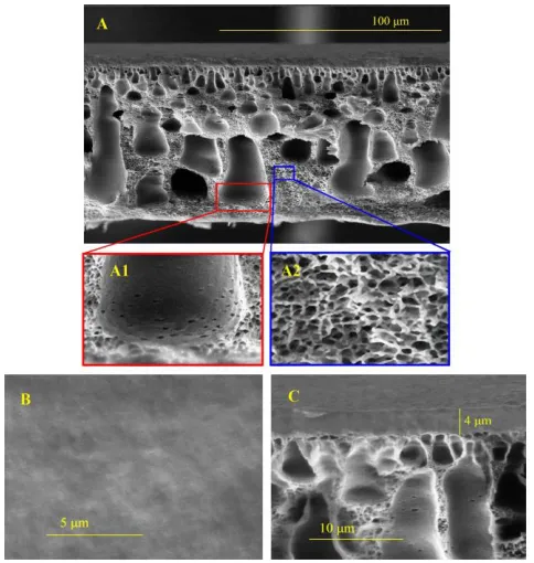
4.2. SEM
I. Khalilinejad et al. / Journal of Membrane Science and Research 1 (2015) 124-129
resistance against the transport of gas molecules that is not expected to accrue any Knudsen diffusion across the PVC support.
4.3. Gas permeation properties
Permeation of N2, CH4 and CO2 gases through the Pebax/PVC thin film
composite membrane was investigated at room temperature and the pressures
of 3, 6 and 10 bar on the thin film composite membrane prepared from 5 wt.% Pebax solution at coating angle of 45°. The permeance and the ideal selectivity results are shown in Fig. 9-A and 9-B. The order of gas permeance was found to be as:
CO2 >> CH4 > N2
Fig. 8. SEM images of the Pebax/PVC thin film composite membrane: (A) cross section, (B) top-layer surface, and (C) magnified cross-section.
Table 1
The permeation properties of CO2, CH4 and N2 gases through the Pebax/PVC TFCs and the Pebax free stand membrane.
*permeance in GPU (1 GPU=1×10⁻⁶ cm3 (STP)/(cm2 s cmHg))
As could be concluded from the permeance results, CO2 is more
permeable than other gases. This may be because of the two mechanisms. First, the more potential of CO2 to diffuse through the polymer matrix due to
its smaller kinetic diameter (3.3 Å) than those of N2 (3.64 Å) and CH4 (3.8 Å) [26]. Second, quadrapolar moments of CO2 in combination with the rubbery
nature of Pebax make it more permeable for CO2 than N2 and CH4. Indeed,
CO2 is a condensable and interactive gas which can interact with the
polymeric chains and the available functional groups. This leads to a high solubility for CO2, and consequently, being more permeable than other gases.
Besides, the lower permeance of N2 might be due to slow diffusivity resulting
from the larger kinetic diameter and lower solubility in the Pebax polymer. Generally, the smaller gas molecules can diffuse faster and have higher permeances [35]; however, in the case of CH4 and N2 in spite of the smaller
size of the nitrogen molecules, methane, thanks to its superior condensability, exhibits a higher permeance than nitrogen. On the other hand, in this case the solubility mechanism can be considered as the dominant mechanism in permeation of gases through Pebax membranes. For rubbery polymers, in general, the permeance of a condensable gas increases with the pressure, while an inverse behaviour is observed for a typical glassy polymer [36]. In this study, the performance of TFCs was improved upon increasing the
pressure from 2 to 10 bar. This phenomenon may be attributed to the higher condensability of CO2 at greater pressures due to increase of the sorption of
the polar CO2 molecule in the polymeric membrane, which already has a
preferential affinity for this gas. The permeance of N2 and CH4 does not
change considerably upon the increase in the upstream pressure. It should be noted that, the effect of pressure on the permeation of polar and non-reactive gases like N2 through the non-porous membrane which follows
solution-diffusion mechanism, is negligible [26].
The influence of feed pressure on membrane performance can be expressed, using the following equation:
m p
(5)
where, π∞ is the permeance at Δp = 0 (infinite dilution gas permeance) and m is characterization factor for permeance dependency of pressure. Values of m for CO2, CH4 and N2 are 0.77, 0.008 and 0.0007 respectively. As it can be
seen, m for CO2 is more than those of other gases, owing to dominant the
4.3.1. Effect of selective layer thickness
Influence of the membrane thickness on the permeation properties is clearly evidence in Table1. With increase of the selective layer thickness from 4 μm (composite membrane) to 20 μm (Pebax free stand membrane) the permeance of CO2, CH4 and N2 has dropped 16.7, 21 and 18%, respectively.
However, the CO2/N2 and CO2/CH4 ideal selectivities approximately were
remained unchanged. The thickness of membrane selective layer has a great effect on gas flux through the membrane, according to the Fick’s law. In fact, the thinner selective layer would result the more gas permeance [22].
4.3.2. Effect of operating temperature
In general, the increase of operating temperature has a great effect on the permeation of small molecules through membranes. In spite of that, the gas permeation of polymeric films containing PEO is strongly dependent on the operating temperature [38]. As demonstrated in Fig. 10-A, with increase in temperature from 25 to 50 °C, the permeances of CO2, CH4, and N2 in the
Pebax/PVC TFCs were increased owing to the mobility increment of the penetrants at higher temperature which was led to enhance the diffusion driving force for the penetrants. Also an increase in the operating temperature, causes to increase in chain mobility and makes the polymer matrix more flexible and increases the available fractional free volume (FFV) which is a linear function of temperature with respect to Equation (6) [39,40].
( )
g
T r g
FFV FFV T T
(6)
where FFVTg is the apparent fractional free volume at Tg, and αr is the thermal expansion coefficient of the fractional free volume in the rubbery phase, (T > Tg).
There is also a linear relationship between logarometric based values of permeability (or permeance) versus invert of temperature as follows [12,38]:
0exp
p E RT
(7)
where, π0 is a pre-exponential value, R is the universal constant of gases (kJ/kmol.K), T is the operating temperature (K) and Ep is the activation energy for gas permeation (kJ/mol). Indeed, the faster permeation through a membrane, the lower is the corresponding value for Ep of the gas. Values of Ep for CO2, CH4 and N2 permeation through Pebax/PVC composite are 14.7,
24.2 and 31.6 kJ/mol, respectively. As it can be seen, Ep for CO2 is less than
those of other gases, due to high diffusivity and solubility of CO2.
Fig. 9. Gas permeation properties of Pebax/PVC thin film composite membrane.
However, the selectivity of the membrane for CO2/N2 and CO2/CH4 was
decreased upon the temperature increase as it shown in Fig. 10-B. This is due to a reduction in CO2 solubility at higher temperatures which tends to reduce
the solubility selectivity and consequently the overall selectivity.
Fig. 10. Effect of temperature on gas separation performance of the TFCs.
4.4. Performance studies
Fig. 11 illustrates a comparison between separation performances of the membranes prepared in the present work (obtained at 2 bar) with the Robeson's upper bounds (2008) of polymeric membranes for CO2/N2 and
CO2/CH4 separations [41]. In general, the PEO containing polymers exhibit
2–3 times higher permselectivity with a similar CO2 permeability than the
non-PEO containing polymers. Although the Pebax/PVC TFC membranes (with approximately 4 μm of selective layer thickness) did not exceed the upper bounds, but displayed a good performance and were locate near the upper bounds.
Fig. 11. Performance of Pebax/PVC thin film membranes compared to the Robeson's upper-bound 2008.
5. Conclusions
The preparation of a thin film composite membrane made of Pebax®1657
I. Khalilinejad et al. / Journal of Membrane Science and Research 1 (2015) 124-129
support. In order to investigate the effect of support and film thickness on the performance of the Pebax membrane, a free stand Pebax film with 20 μm of thickness was also fabricated.
Gas permeation properties of the selective layers with different thickness defined that the permeances of all gases decrease upon the increase in the film thickness. However, the CO2/N2 and CO2/CH4 selectivities remained almost
unchanged. In addition, the performances of the Pebax/PVC TFCs were investigated under various pressures and temperatures. The CO2 permeance
and CO2/N2 and CO2/CH4 selectivities improved with the increase in pressure.
This behaviour may be attributed to the high solubility and plasticizing effect of CO2 at higher pressures. With the increase in operating temperature, the
CO2 permeance increased and the selectivities were decreased considerably. However, the performance of the Pebax/PVC TFC membranes was higher than the Pebax free stand film membrane.
References
[1] E.S. Rubin, H. De Coninck, IPCC special report on carbon dioxide capture and storage, UK Cambridge Univ. Press., TNO cost curves CO2 storage, Part 2, 2005.
[2] A. Kargari, M. Takht Ravanchi, Carbon dioxide: capturing and utilization, in: G. Liu, (Ed.), Greenhouse gases, 1st Ed., Vol. 1, Intech, Croatia, 2012, pp. 3–30.
[3] S.G. Lovineh, M. Asghari, G. Khanbabaei, CO2 permeation through poly
(amide-6-b-ethylene oxide)-nanosilica membranes, Appl. Surf. Sci. 318 ( 2014) 176-179. [4] M.K. Mondal, H.K. Balsora, P. Varshney, Progress and trends in CO2
capture/separation technologies: A review, Energy 46 (2012) 431–441.
[5] Z. H. Lee, K.T. Lee, S. Bhatia, A.R. Mohamed, Post-combustion carbon dioxide capture: Evolution towards utilization of nanomaterials, Renew. Sustain. Energ. Rev. 16 (2012) 2599–2609.
[6] R. W. Baker, K. Lokhandwala, Natural gas processing with membranes: an overview, Ind. Eng. Chem. Res. 47 (2008) 2109–2121.
[7] M. Takht Ravanchi, A. Kargari, New advances in membrane technology, in: K. Jayanthakumaran (Ed.), Advanced technologies, 1st ed., Vol. 1, InTech, Croatia,
2009, pp. 369–394.
[8] A. Brunetti, F. Scura, G. Barbieri, E. Drioli, Membrane technologies for CO2
separation, J. Membr. Sci. 359 (2010) 115–125.
[9] T.C. Merkel, H. Lin, X. Wei, R. Baker, Power plant post-combustion carbon dioxide capture: An opportunity for membranes, J. Membr. Sci. 359 (2010) 126–139. [10] D. Shekhawat, D.R. Luebke, H.W. Pennline, A review of carbon dioxide selective
membranes, US Dep. Energy, 2003.
[11] G. Maier, Gas separation by polymer membranes: Beyond the border, Angew. Chem. Int. Ed. 52 (2013) 4982–4984.
[12] L.M. Robeson, Polymer membranes for gas separation, Curr. Opin. Solid State Mater. Sci. 4 (1999) 549–552.
[13] M. Rezakazemi, A. Ebadi Amooghin, M.M. Montazer-Rahmati, A.F. Ismail, T. Matsuura, State-of-the-art membrane based CO2 separation using mixed matrix
membranes (MMMs): An overview on current status and future directions, Prog. Polym. Sci. 39 (2014) 817–861.
[14] M. Takht Ravanchi, T. Kaghazchi, A. Kargari, Application of membrane separation processes in petrochemical industry: a review, Desalination 235 (2009) 199–244. [15] M. Czyperek, P. Zapp, H.J. M. Bouwmeester, M. Modigell, K. Ebert, I. Voigt, W.
A. Meulenberg, L. Singheiser, D. Stöver, Gas separation membranes for zero-emission fossil power plants: MEM-BRAIN, J. Membr. Sci. 359 (2010) 149–159. [16] H. Sanaeepur, A.E. Amooghin, A. Moghadassi, A. Kargari, Preparation and
characterization of acrylonitrile–butadiene–styrene/poly (vinyl acetate) membrane for CO2 removal, Sep. Purif. Technol. 80 (2011) 499–508.
[17] Y. Yampolskii, Polymeric gas separation membranes, Macromolecules 45 (2012) 3298–3311.
[18] R.D. Noble, Perspectives on mixed matrix membranes, J. Membr. Sci. 378 (2011) 393–397.
[19] R.W. Baker, Membrane technology and applications, 3rd Ed., John Wiley & Sons,
Ltd, West Sussex, UK, 2012.
[20] L. Zhao, E. Riensche, R. Menzer, L. Blum, D. Stolten, A parametric study of CO2/N2 gas separation membrane processes for post-combustion capture, J. Membr.
Sci. 325 (2008) 284–294.
[21] C.E. Powell, G.G. Qiao, Polymeric CO2/N2 gas separation membranes for the
capture of carbon dioxide from power plant flue gases, J. Membr. Sci. 279 (2006) 1–49.
[22] K. Ebert, Thin film composite membranes of glossy polymers for gas separation: preparation and characterization, PhD Tesis, University of Twente, Enschede, The Netherlands, 1995.
[23] Y. Yampolskii, B. D. Freeman, Membrane gas separation, John Wiley & Sons Ltd, West Sussex, UK, 2010.
[24] L.E.M. Gevers, S. Aldea, I.F.J. Vankelecom, P.A. Jacobs, Optimisation of a lab-scale method for preparation of composite membranes with a filled dense top-layer, J. Membr. Sci. 281 (2006) 741–746.
[25] M.R. Dalwani, Thin film composite nanofiltration membranes for extreme conditions, PhD Thesis, University of Twente, Enschede, The Netherlands, 2011. [26] R.S. Murali, A.F. Ismail, M.A. Rahman, S. Sridhar, Mixed matrix membranes of
Pebax-1657 loaded with 4A zeolite for gaseous separations, Sep. Purif. Technol. 129 (2014) 1–8.
[27] R.S. Murali, K.Y. Rani, T. Sankarshana, A.F. Ismail, S. Sridhar, Separation of binary mixtures of propylene and propane by facilitated transport through silver incorporated poly (ether-block-amide) membranes,” Oil Gas Sci. Technol. d’IFP Energ. Nouv., Open Access, 2014.
[28] A. Car, W. Yave, K.-V. Peinemann, C. Stropnik, Tailoring polymeric membrane based on segmented block copolymers for CO2 separation, in: Y. Yampolskii, B.D.
Freeman (Eds.), Membrane gas separation, John Wiley & Sons Ltd, West Sussex, UK, 2010,pp. 227-253.
[29] X. Zhang, Y. Chen, A.H. Konsowa, X. Zhu, J.C. Crittenden, Evaluation of an innovative polyvinyl chloride (PVC) ultrafiltration membrane for wastewater treatment, Sep. Purif. Technol. 70 (2009) 71–78.
[30] J. Xu, Z.-L. Xu, Poly (vinyl chloride) (PVC) hollow fiber ultrafiltration membranes prepared from PVC/additives/solvent, J. Membr. Sci. 208 (2002) 203–212. [31] J.G. Wijmans, R.W. Baker, The solution-diffusion model: a review, J. Membr. Sci.
107 (1995) 1–21.
[32] W.J. Koros, G.K. Fleming, Membrane-based gas separation, J. Membr. Sci. 83 (1993) 1–80.
[33] G.R. Guillen, Y. Pan, M. Li, E.M.V. Hoek, Preparation and characterization of membranes formed by nonsolvent induced phase separation: a review, Ind. Eng. Chem. Res. 50 (2011) 3798–3817.
[34] Standard test method for pore size characteristics of membrane filters by bubble point and mean flow pore test, Vol. 27, Annual book of ASTM standard, F316-03, 2000.
[35] M. Sadeghi, G. Khanbabaei, A.H.S. Dehaghani, M. Sadeghi, M.A. Aravand, M. Akbarzade, S. Khatti, Gas permeation properties of ethylene vinyl acetate–silica nanocomposite membranes, J. Membr. Sci. 322 (2008) 423–428.
[36] J.H. Kim, S.Y. Ha, Y.M. Lee, Gas permeation of poly (amide-6-b-ethylene oxide) copolymer, J. Membr. Sci. 190 (2001) 179–193.
[37] H. Rabiee, A. Ghadimi, T. Mohammadi, Gas transport properties of reverse-selective poly (ether-b-amide6)/[Emim][BF4] gel membranes for CO2/light gases
separation, J. Membr. Sci. 476 (2015) 286-302.
[38] J.H. Kim, Y.M. Lee, Gas permeation properties of poly (amide-6-b-ethylene oxide)– silica hybrid membranes, J. Membr. Sci. 193 (2001) 209–225.
[39] H. Lin, B.D. Freeman, S. Kalakkunnath, D.S. Kalika, Effect of copolymer composition, temperature, and carbon dioxide fugacity on pure-and mixed-gas permeability in poly (ethylene glycol)-based materials: Free volume interpretation, J. Membr. Sci. 291 (2007) 131–139.
[40] B.W. Rowe, L.M. Robeson, B.D. Freeman, D.R. Paul, Influence of temperature on the upper bound: Theoretical considerations and comparison with experimental results, J. Membr. Sci. 360 (2010) 58–69.
[41] L.M. Robeson, The upper bound revisited, J. Membr. Sci. 320 (2008) 390–400.
![Fig. 1. A schematic of a thin film composite membrane [25].](https://thumb-us.123doks.com/thumbv2/123dok_us/8425969.1695937/2.595.89.252.425.485/fig-schematic-film-composite-membrane.webp)