Receiving more than data - a signal model, theory
and implementation of a cognitive IEEE 802.15.4
receiver
Tim
Esemann
1,∗,
Horst
Hellbrück
11LübeckUniversityofAppliedSciences,GermanyDepartmentofElectricalEngineeringandComputer
ScienceCoSACenterofExcellence
Abstract
Standard medium access schemes sense the channel immediately prior transmission, but are blind during the transmission. Therefore, standard transceivers have limited cognitive capabilities which are important for operation in heterogeneous radio environments. Specifically, mobile interferers move gradually into the reception range before actually causing collisions. These gradual interferences cannot yet be detected, and upcoming collisions cannot be predicted. We present a theoretical analysis of the received and demodulated signal. This analysis and the derived signal model verifies that the received signal contains more than transmitted data exclusively. Enhanced signal processing extracts signal components of an interference at the receiver and enables advanced interference detection to provide information about approaching mobile interferers. Our theoretical analysis is evaluated by simulations and experiments with an IEEE 802.15.4 transmitter and an extended cognitive receiver.
Receivedon 13 May 2016;acceptedon 06 August 2016;publishedon 05 September 2016
Keywords: cognitive communication system, cognitive radio, spectrum sensing
Copyright © 2016 T. Esemann and H. Hellbrück, licensedto EAI. This is anopen access article distributedunder the terms oftheCreativeCommonsAttributionlicense(http://creativecommons.org/licenses/by/3.0/),whichpermits unlimiteduse,distributionandreproductioninanymediumsolongastheoriginalworkisproperlycited.
doi:10.4108/eai.5-9-2016.151646
1. Introduction
The number of devices with wireless interfaces is continuously increasing. Many of these devices operate in the limited spectrum available for unlicensed ISM bands. Many wireless standards and technologies compete for spectrum access within the same frequency range. In the 2.4 GHz ISM band we have IEEE 802.11 (WLAN), IEEE 802.15.1 (Bluetooth), and IEEE 802.15.4 (in some literature named Zigbee). In addition, several proprietary wireless transmissions operate in this frequency range. Therefore, spectrum utilization in the unlicensed ISM band is very heterogeneous and concurrent transmission with interference occurs regularly. Concurrent transmission occurs when at least two wireless transmitters utilize the same frequency spectrum, or parts of the same spectrum while a receiver is in reception range. During a concurrent
∗
Tim Esemann Email:[email protected]
transmissions, the signals interfere with each other at the receiver. Strong interference degrades the performance of a wireless system because transmission errors occur. The term collision is used preferably with competing devices using the same standard. Wireless standards like IEEE 802.15.4 apply carrier sensing to avoid collisions and interference [1]. Carrier sensing is performed prior to the start of transmission, but the transceiver is "blind" during the actual transmission.
Although this is a general problem for wireless transmissions, in this article we will focus on a solution for IEEE 802.15.4. A pair of standard IEEE 802.15.4 transceivers are not able to detect and identify interference reliably during transmission and reception. To the best of our knowledge, we are the first to propose a cognitive receiver for IEEE 802.15.4 to enable spectrum awareness during transmission. The contributions are as follows: We provide a theoretical analysis of quadrature demodulated signals and interferences. We introduce a new model for
EA
EAI Endorsed Transactions
on
Cognitive Communications
an extension of the physical layer (PHY) of an IEEE 802.15.4 transceiver towards a cognitive receiver. We provide both, simulation and experimental results of our implementation with GNU Radio. This article is an extension of a published conference paper [2]. Therefore, the new contributions comprise a method to detect concurrent interference during transmission and identify the time interval of occurrence. Furthermore, we provide implementation details of a cognitive IEEE 802.15.4 receiver and propose a corresponding extension of the IEEE 802.15.4 protocol. Our results demonstrate that we have reached one step further towards a cognitive transceiver.
The rest of this article is organized as follows: Section2will introduce related work and demonstrate the need for new approaches. We will analyze the problem of concurrent interference and its impact as signal marks on a received signal in Section3. Section4 evaluates the theory using simulations. Implementation of a cognitive transceiver and a proposed extension of the IEEE 802.15.4 protocol is described in Section5. The paper concludes with a short summary and presents future work in Section6.
2. Related work
The goal of our approach is to increase spectrum awareness during transmission. We will introduce recently published approaches for advanced spectrum sensing prior to and during an ongoing transmission and discuss it in relation to our work.
Akyildiz et al. describe in [3] that spectrum sensing is an important requirement to exploit unused frequencies. The authors distinguish between in-band and out-of-band sensing. In contrast to our work, in-band sensing in [3] is only considered prior to transmission. Therefore, a trade-off between sensing and transmission has to be found in order to gain reasonable interference avoidance and transmission period. On the other hand, out-of-band sensing is able to sense other frequency bands during an ongoing transmission, but not in the band that is currently utilized for transmission. A comprehensive summary of spectrum sensing schemes is given by Yücek and Arslan in [4] and Ariananda et al. in [5]. The sensing schemes under investigation have made a variety of achievements in performance and accuracy. Schemes providing more detailed spectrum awareness are usually more complex and time-consuming. The three most prevalent schemes are energy detection, cyclostationary feature detection, and matched filters. All schemes perform sensing prior to transmission and not during transmission. To ensure spectrum awareness during transmission in the previously mentioned solutions, a third radio for sensing is required. Through
the use our approach, one pair of transceivers is sufficient.
Another solution to perform spectrum sensing during transmission is cooperative spectrum sensing. A survey on cooperative spectrum sensing, in order to increase spectrum awareness, is given by Akyildiz et al. in [6]. With cooperation of multiple spatially separated sensing devices, spectrum awareness can be significantly improved. On the other hand, this requires more operational effort due to multiple sensing devices and additional overhead from exchanging sensing information. Cooperative sensing cannot be implemented with a single transceiver pair.
In the past, new approaches for spectrum sensing during transmission were introduced. In [7] the authors propose to divide the transmission band into sub-bands, where a redundant sub-band is continuously used for spectrum sensing. This reduces bandwidth efficiency because a redundant frequency range with no data transmission is required. Another approach to achieve spectrum awareness during an ongoing transmission is to utilize multicarrier waveforms, and to analyze subcarriers at the receiver. In [8] Farhang-Boroujeny suggests measuring and comparing the energy of each received subcarrier in order to detect concurrent transmissions. It allows in-band concurrent transmitter detection even during ongoing transmissions, but requires wideband multicarrier transmission which is not available for IEEE 802.15.4 devices. Although energy detection is proposed, it is still not possible to identify any specific signal marks from other interferer. With recent advances in full-duplex wireless communication [9] schemes, like simultaneous transmit-and-sense seem to be achievable in the future. However, to the best of our knowledge, current results have not yet exceeded the status of preliminary experiments [10] and analytical examination of the advantages [11]. Furthermore, our approach does not require any additional complex antenna configuration within transmit and receive path.
In conclusion, several techniques and schemes to pro-vide spectrum awareness have been introduced in the past. Spectrum sensing schemes prior transmission pro-vide information about effects only during execution, but not during subsequent transmission.Spectrum sens-ing schemes dursens-ing transmission either require redun-dant sub-bands for sensing, multicarrier waveforms, or complex antenna circuitry and configuration. In the following sections, we will describe how small signal interference changes the received signal and how to build a radio receiver for IEEE 802.15.4 that receives more than data.
2 EAI Endorsed Transactions on
Cognitive Communications
04 - 09 2016|Volume2|Issue7|e3
EAI
European Alliance3. Problemand analysis
As introduced in Section 1 the increasing utilization of wireless systems will result in a heterogeneous and dynamic radio environment. In such a radio environment concurrent wireless transmissions using the same frequency range will interfere with each other. Many of these radio transceivers are mobile today. A mobile and transmitting transceiver, appearing in the scene interferes with low power first and with closer distance it finally disrupts the transmission of other systems and causes collisions. Hence, it is important to detect such interfering device reliably in advance and before collisions occur.
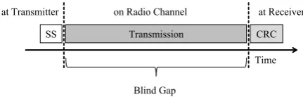
Today’s wireless systems like an IEEE 802.15.4 [1] transceiver use Carrier Sense Multiple Access with Col-lision Avoidance (CSMA/CA) in a heterogeneous radio environment. Transceivers perform carrier sensing (a simple energy detection) immediately prior to trans-mission. If no other transmission is detected during spectrum sensing the transmitter starts its own trans-mission. After the receiver has decoded the data frame, it is checked for transmission errors by calculating the cyclic redundancy check (CRC). Bit errors that occur are detected reliably with CRC but the reason cannot be identified. Consequently, spectrum awareness can only be provided during the spectrum sensing period (SS) as illustrated in Figure 1 by the white back-ground. During the transmission and reception there is a "blind gap" illustrated by the grey background. In the IEEE 802.15.4 standard the measurement duration for carrier sensing is specified to be 128us (measure-ment duration of 8 symbols [1] p.54). With maximum transmission duration of 4.2 ms this yields a spectrum awareness of only 3% of the total time interval. With minimum transmission duration (by sending acknowl-edgement frames) spectrum awareness is increased to not more than 25% of the total time interval.
SS Transmission CRC Time at Transmitter on Radio Channel at Receiver
Blind Gap
Figure 1. Limited spectrum awareness during transmission
The aim of our work is to show that it is possible to receive more than just data in order to improve spectrum awareness during transmission. We propose to analyze the received and demodulated signal of single received frames or even parts of these frames, for marks of another concurrent interfering signal. Our theoretical analysis shows that the received signal includes information about interference occurring during an ongoing transmission. Therefore, we propose
adding cognitive capabilities to the receiver. This is the basis for future work on signal processing of the received signal. First preliminary results, from experiments analyzing the received signal at the receiver and a conceptual hardware setup are published in [12, 13]. Our previous work shows an implementation with a basic modulation scheme (MSK), and a preliminary study to integrate it into a standard receiver. The work provided neither a signal model and nor a theoretical analysis of the received and demodulated signal.
In our approach we assume that the interfering signal is still not large enough to cause a collision and transmission errors. This assumption is reasonable, especially in a heterogeneous environment with mobile devices. In this environment a radio transceiver needs to be very sensitive to concurrent radios to avoid interfering with their transmissions. It is important to detect the signal of a concurrent radio on an overlapping frequency band as soon as possible to adapt transmission parameters accordingly before a collision occurs. After this initial explanation we will describe the digital demodulation process and provide mathematical expressions for an Offset Quadrature Phase Shift Keying (OQPSK) modulated signal. The theoretical analysis and model were validated by simulations and experiments with a real IEEE 802.15.4 radio link. Furthermore, our concept was adapted to IEEE 802.15.4 transmission without affecting standard compliant data transfer. For simplicity, the presented mathematical analysis does not consider noise in the environment. However, the experimental results in Section 4 show that the analytic results hold also for noisy signals.
3.1. Quadrature demodulation of an OQPSK
modulated signal with interference
The Offset Quadrature Phase Shift Keying (OQPSK) signal can be written as [14]:
sOQP SK(t) =ac[mI(t) cos(ωct) +mQ(t) sin(ωct)] (1)
OQPSK utilizes half-sine pulse shaping, mI(t) and
mQ(t). Where in-phase (I) and quadrature component
(Q) are misaligned by half a symbol duration. The demodulation of such a OQPSK signal with a quadrature demodulator follows several stages as depicted in Figure 2. Equation2 to 4 show the result of each stage in detail. First, the received OQPSK modulated and real signal srecO(t) is converted by the
Hilbert transform into a complex signalSrecO(t).
Second, the complex signal is quadrature demodulated, resulting inSO(t).
SO(t) =Srec(t)×e
−jωct
=ac[mI(t) cos(ωct) +jmQ(t) sin(ωct)]
×[cos(ωct)−jsin(ωct)]
=ac[mQ(t) + (mI(t)−mQ(t)) cos2(ωct)
| {z }
ISO(t)
+j(mQ(t)−mI(t)) cos(ωct) sin(ωct)
| {z }
QSO(t)
] (3)
Third, the phase angle of the demodulated signalϕ(t) is determined with arctangent function. Finally, bit decision is made based on the determined phase angle ϕ(t).
ϕ(t) = arctan Qs(t) Is(t)
!
(4)
Figure 2. Demodulation of OQPSK signal
Interferencei(t)
Rx Signal srx(t)
Tx Signal stx(t)
+ Radio Channel
RF Frontend
Demodul-ation srec(t)
Figure 3. Reception of a transmitted signal with superimposed interference from a concurrent transmitter
If another concurrent radio signali(t) interferes with the transmitted OQPSK modulated signalsOQP SK(t), it
is superimposed as shown in (5) and Figure3.
srecOI(t) =sOQP SK(t) +i(t) (5)
With concurrent transmission, (2) and (3) are extended by additional components (Interf erence) as shown in (6) and (7). ˆS and ˆI are the Hilbert transformed signal components of the OQPSK and the interfering signal.
SrecOI(t) = [SOQP SK(t) +I(t)] +j[ ˆSOQP SK(t) + ˆI(t)] (6)
SOI(t) =Srec(t)×e
−jωct
=SOQP SK(t)×e
−jωct
+I(t)×e−jωct
=
ISoqpsk(t)
| {z }
OQP SK only
+I(t) cos(ωct) + ˆI(t) sin(ωct
| {z }
Interf erence
)
| {z }
ISOI(t)
+jhQSoqpsk(t)−I(t) sin(ωct) + ˆI(t) cos(ωct)
i
| {z }
QSOI(t)
(7)
Finally, inserting the corresponding Is(t) and Qs(t)
component into (4) results in the phase angle of the demodulated signal that additionally contains signal marks of the interfering signal. In order to extract the influence of interference, we introduce an extension of a traditional receiver which is presented in the next section.
3.2. Interference extraction out of received OQPSK
modulated signal
To extract the influence of the interference signal we apply a method which is known from interference cancellation techniques [15]. But, here we apply it the other way around. We extract the interference signal components from the demodulated signal as shown in Figure4and Equation8.
Demodul-ation
Data Decision
Device
+ Dem. SignalRegenerate S(t)
Interference Extraction Extracted Influence
of Interference Inf(t)
-OQPSK(t)
Figure 4. Interference extraction
ϕint(t) = ϕs(t)
|{z}
received
−ϕOQP SK(t)
| {z }
regenerated
=Inf(t) (8)
Remember, that we consider cases where the inter-ference is still not large enough to cause transmission errors. Demodulated and decoded data is used to regen-erate the demodulated signalϕOQP SK(t) as it would be
without the effects from interference. This regenerated signalϕOQP SK(t) is subtracted from the actual received
and demodulated signal ϕs(t) including the
interfer-ence. Inserting the in-phase I(t) and quadrature Q(t) components from (7) (received) and (3) (regenerated) into arctangent of (4) and successively into (8) results in
4 EAI Endorsed Transactions on
Cognitive Communications
04 - 09 2016|Volume2|Issue7|e3
EAI
European Alliancea rather more complex expression. Corresponding sig-nal marks from the interfering sigsig-nal are hardly observ-able within this complex term. Therefore, we further simplify this expression by applying an approximation. Considering an interfering signal with signal strength that is much smaller than our actually transmitted and received signal, we use the approximation that:
lim
x→0tanx
≈x (9)
Instead of (8) the approximated influence of interfer-enceInfg(t) is expressed as:
ϕint(t)≈tan
ϕint(t)
=Infg(t) (10)
This approximation and (8) results in the following term:
tanϕint(t)
= tanϕs(t)−ϕOQP SK(t)
= tan
ϕs(t)
·tanϕOQP SK(t)
1 + tanϕs(t)
·tanϕOQP SK(t) (11a)
At first glance this does not seem to be a true simplification, but the tangent suspends the arctangent from (4). As shown in the following section these assumptions will simplify the expression ofInf(t).
3.3. Influence of interference
We consider a sinusoidal signal to show the influence of the superimposed interfering signal.
icos(t) =aicos(ωit+ϕi) (12)
If this interference signal is inserted in (7), we get:
Is(t) =ISoqpsk(t) +aicos(ωit+ϕi)·cos(ωct)
+aisin(ωit+ϕi)·sin(ωct)
=ISoqpsk(t) +aisin
(ωi −ωc)t+φi
(13a)
Qs(t) =QSoqpsk(t) +aicos
(ωi−ωc)t+φi
(13b)
With (11) and further trigonometric identities, and successive simplifications, this yields in Equation14.
The coefficients and parameter of Equation14are as follows:
c1=ac,c4=ai ,c2=mI(t) ,c3=mQ(t)
α=ωct,β=
(ωi−ωc)t+φi
The resulting term ofInfg(t) includes signal components and therefore marks of the superimposed sinusoidal interference. It is influenced by its amplitude ai,
frequencyωi and phaseφi. Corresponding examples of
such signals are depicted in Figure5. The upper signal presents the demodulated signal with interference.
The second signal presents the demodulated signal without the effects from interference, respectively the regenerated demodulated signal. The example of an extracted influence of interference in the third graph is a result of a sinusoidal interference with a SIR of 14 dB and a frequency of 50 kHz. The extracted influence of interference shows significant signal marks caused by the interfering signal. The width of the sinusoidal cycles is dependent on the frequencies of the transmitted and interfering signals, ωc and ωi. Amplitude of the
interfering signal determines the amplitude values of the extracted influence of interference. This is because the amplitude of the interferenceai, i.e.c4, is not part
of the last two sinusoidal terms of denominator of Equation 14 and these components stay constant ifc4
varies. Whereas the transmitted symbols corresponding to mI(t) and mQ(t) and the phase of interfering φi
determines the phase shifts.
The results in this section show that the extracted influence of an interfering signal after demodulation, contains signal marks corresponding to the interfering signal. The presented signal model is validated in the next section with baseband simulation, experiments with an OQPSK modulated signal, and a superimposed OQPSK modulated interfering signal.
4. Evaluation
We have implemented an extended IEEE 802.15.4 receiver with software defined radios (SDR) composed of an USRP2 [16] and signal processing with GNU Radio [17]. USRP2 is a hardware frontend for GNU Radio applications responsible for up- and down-conversion of RF signals and furthermore for digital-to-analog and analog-to-digital conversion. Our extended IEEE 802.15.4 receiver is completely implemented in GNU Radio. Signal processing relevant to IEEE 802.15.4, i.e. demodulation and decision device, is based on the work of Schmid, presented in [18]. The block diagram of the receiver is depicted in Figure 6. The received IEEE 802.15.4 signal is A/D-converted with a sampling frequency of 4 MS/s. After demodulation including clock recovery the sample rate of the digital signal is 2 MS/s corresponding to the chip rate 2 MChips/s of a standard IEEE 802.15.4 transmission. An IEEE 802.15.4 transmitter is set up accordingly.
4.1. Baseband simulation with OQPSK
g
Inf(t) = c4c3cos
β+c4(c2−c3) cos
αcosα−β
c4c3sin
β+c4(c2−c3) cos
αsinα−β+c1c2cos(α)2+c1c3sin(α)2
(14)
-20 2
0 20 40 60
Demodulated Signal with Interference - ϕ(t)
-20 2
0 20 40 60
Regenerated Demodulated Signal
-1 0 1
0 20 40 60
Extracted Influence of Interference - Inf(t)
Figure 5. Interference extraction with sinusoidal interference for 64 demodulated bits
USRP2 Received
Signal
Demodul-ation
Data Decision
Device
- Dem. SignalRegenerate
Demodulated Signal
Interference Extraction Extracted Influence
of Interference Inf(t)
Memory Baseband
Traditional Receiver
Extension
Figure 6. Extended receiver implemented with GNU Radio
Considering Equation5this yields in:
srec(t) =sOQP SK−T x(t) +sOQP SK−Interf erer(t) (15)
A carrier frequency offset of 50 kHz compared to the original Tx-signal was chosen to simulate another concurrent OQPSK transmitting radio device. The resulting signals are depicted in Figure 7, again with an SIR of 14 dB. The occurring signal marks caused by the interfering OQPSK signal are dependent on the transmitted data of the original transmitter and the interferer. For this simulation, the interfering transmitter signal is modulated with random data. If the data is incidentally similar to the data transmitted by the original transmitter the amplitude of the influence of interference is close to zero. See the start of the depicted signal Inf(t). Compared to the extracted influence of interference of a sinusoidal interference, the signal shape shows more complex variations. This is due to the dependency of the in-phase
and quadrature part of the interfering signal, which are varied by its OQPSK modulation. Nevertheless, baseband simulation showed that even with a more complex interfering signal observable signal marks occur in the extracted influence of interference.
-20 2
0 20 40 60
Demodulated Signal with Interference - ϕ(t)
-1 0 1
0 20 40 60
Extracted Influence of Interference - Inf(t)
Figure 7. Interference extraction with OQPSK interference for 64 demodulated bits
4.2. Measurement with an extended IEEE 802.15.4
receiver
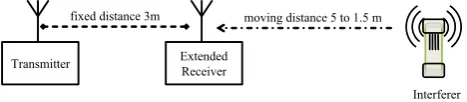
Finally, the extended IEEE 802.15.4 receiver was eval-uated in a real and therefore noisy radio environment with a mobile IEEE 802.15.4 interferer as depicted in Figure 8. Distance between IEEE 802.15.4 transmit-ter and extended receiver was fixed to 3 m. Distance between the concurrent and interfering IEEE 802.15.4 transmitter and the extended receiver was varied from 5 to 1.5 m. At a distance of 1.5 m between receiver and interferer single chip errors start to occur and therefore risk of an upcoming collision arises.
Transmitter Extended Receiver
Interferer fixed distance 3m moving distance 5 to 1.5 m
Figure 8. Measurement setup for moving interferer
Short frames, comparable to an acknowledgement frame, were transmitted within the experiment. A section of the extracted influence of interference for 384 chips is depicted in Figure 9. An initial measure-ment without an interfering signal was conducted first. No significant signal marks are present except noisy variations of the amplitude. Subsequently, the distance between interferer and extended receiver was shortened from 5 m to 1.5 m. At the beginning of each section depicted in Figure9no interference is present. Between the 130th and 190th chip in both plots the interferer starts its transmission, and therefore, superimposes its
6 EAI Endorsed Transactions Cognitive Communicationson
04 - 09 2016|Volume2|Issue7|e3
EAI
European Alliancesignal. At this point in time, the amplitude of the extracted influence of interference increases by approx-imately 10 dB (5 m) and 20 dB (1.5 m) respectively. Even if the interferer is 5 m away from the extended receiver, the occurring signal marks are observable inInf(t).
-2 0 2
0 64 128 192 256 320 384
0dB
No Interference
-2 0 2
0 64 128 192 256 320 384
10dB
Distance to Interferer 5m
-4 0 4
0 64 128 192 256 320 384
20dB
Distance to Interferer 1.5m
Figure 9. Extracted influence of interference Inf(t) for 384 demodulated chips for different distances between cognitive receiver and interferer
The conducted simulations and experiments show that concurrent and interfering transmission generate signal marks within the received and demodulated signal. With an extended receiver, we will be able to receive more than data. Note, that no additional third radio is required in our approach.
4.3. Interference cognition on reception
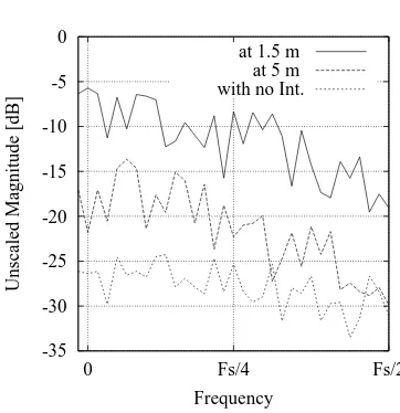
In order to detect and identify the concurrent interfering signals, further signal processing is applied to the extracted influence of interference signal described in the previous section. The signal is grouped into k sets of N = 64 samples. Each set corresponds to a transmitted octet of data and is analyzed with an FFT. Our first experimental implementation of this set-by-set FFT analysis is presented in [19]. The number of calculated sets of FFTs corresponds to the number of transmitted data bytes (octets) in the MAC payload. With the separation into single sets, it is possible to identify when and how long the interference occurred. In order to identify the interfering source, all calculated FFTs of a received data frame are averaged at the end to observe the characteristic spectral shape. More details are presented in [19]. The corresponding averaged FFTs to the signals in Figure9are shown in Figure10. If no interference is present the resulting spectrum remains flat. With decreasing distance between interferer and receiver the interference power of the concurrent signal increases.
In our preliminary studies we introduced the IDOR index (Interference Detection on Reception). It was
-35 -30 -25 -20 -15 -10 -5 0
0 Fs/4 Fs/2
Unscaled Magnitude [dB]
Frequency at 1.5 m
at 5 m with no Int.
Figure 10. Averaged FFTs for different distances between receiver and interferer
defined as the ratio of the magnitude values of the FFT in the unit dB. In this work we enhance it to the so called ICOR index (Interference Cognition on Reception) and classify it as a quartet with four parameters:
ICOR= [IDOR, ncount, kstart, kend] (16)
First, we define the IDOR factor as the ratio between the PSD (power spectral density) of the averaged FFT with (FI) and without (FS) interference:
IDOR= 1
N
N
X
i=0
F2I,i−F2
S,i (17)
This ratio is specified in dB. According to the FFTs in Figure 10 the IDOR factor at a distance of 5 m is equal to 16 dB and increases to 35 dB at a distance of 1.5 m. ncount specifies the number of sets with
signal marks from an interfering source and therefore in how many sets interference is present. The presence of interference is supposed if the amplitude of the extracted interference increases by at least 6 dB. Finally, the number of the first set (kstart) with interference and
the last set with interference (kend) is included in the
index. Ifkend is equal to the last received octet of data,
interference may continue longer than the observed time. Ifncount =kend−kstart, the interference is present
during the complete time period betweenkstartandkend.
Ifncount< kend−kstart, it indicates that more than one
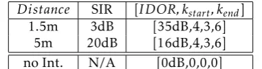
interfering transmission is detected. In both cases from Figure 9 the interference starts to occur in the third set of samples, between 128th and 192th sample. The interference is still present at the end of the sixth set of samples. Therefore, the interference is present in four sets (ncount = 4). In summary, the ICOR indices for the
Distance SIR [IDOR, kstart, kend]
1.5m 3dB [35dB,4,3,6]
5m 20dB [16dB,4,3,6]
no Int. N/A [0dB,0,0,0] Table 1. ICOR index according to the measurements
The ICOR index provides information about the occurrence and duration of a concurrent interference during transmission. The index is applied in the following section to a setup with a pair of cognitive transceivers.
5. IEEE 802.15.4 cognitivereceiver
The Interference Cognition on Reception (ICOR) index described in the previous section is implemented to extend a traditional IEEE 802.15.4 receiver in order to enhance its cognitive behavior. The implementation is completed in GNU Radio. The receiver detects an inter-ference during reception and notifies the transmitter of the occurrence. The next section describes imple-mentation details, followed by a proposal to extend the IEEE 802.15.4 protocol.
5.1. Implementation in GNU Radio
The implementation in GNU Radio is based on the work of Bloessl et. al [20]. The transceiver has a layered structure including an extended physical layer (PHY), medium access layer, and a cognitive engine as shown in Figure11. Hardware frontends of the physical layer are USRP2 devices equipped with a dipole antenna as in the previous experiments. The demodulated and retrieved MAC protocol data unit (MPDU) including the data frame and the corresponding ICOR index are passed to the MAC layer. Wherein the ICOR index is forwarded to the cognitive engine. Inversely, the cognitive engine is able to send an ICOR result to the MAC layer. The MAC layer encapsulates the command into a MPDU of a MAC command frame and passes it to the PHY layer.
The extended PHY is depicted in Figure 12. The decision device is included within the available quadrature demodulator from GNU Radio. Therefore, it only provides data output. Thus, a special demodulator is implemented in order to access demodulated signals needed for interference extraction. The demodulator passes the signal as a stream of float values to the interference extraction. The interference extraction block retrieves the received data and generates the extracted influence of interference signal. A message parsing interface passes the retrieved data to the set-by-set FFT block. Whereas a signal stream passes the extracted interference. The FFT block separates the extracted interference into k sets of N samples in order to calculate the set-by-set FFTs. With the
Extended IEEE 802.15.4 PHY Layer UHD USRP
Source
IEEE 802.15.4 MAC Layer Cognitive Engine
UHD USRP Sink ICOR
Index
ICOR Result
MPDU +
ICOR Index MPDU
USRP Control Command USRP Control
Command
Received Baseband Signal
Transmitting Baseband Signal
to upper Layer from upper
Layer
Figure 11. Cognitive IEEE 802.15.4 transceiver implemented in GNU Radio
separation into sets we are able to identify the time the interference occurred during the transmission. Finally, the ICOR index is determined and added as meta data to the received message from the interference extraction block. Therefore, the message passed to the MAC layer includes the MAC header, data payload, footer and the ICOR index.
Extracted Influence of Interference Signal (float) Modified
Quadrature Demodulator
Interference Extraction PHY in
Received Baseband Signal (complex)
set-by-set FFT Demodulated
Signal (float)
Received MAC Protocol Data Unit (message)
PHY out Data Frame with ICOR Index (message)
Figure 12. Extended physical layer implemented in GNU Radio
In order to integrate the interference cognition on reception into IEEE 802.15.4 receiver, we propose to extend the protocol as described in the next section.
5.2. Protocol extension
Figure13depicts the complete procedure at the receiver to identify interference during transmission and send a corresponding ICOR result to the transmitter. The receiver starts the interference cognition on reception once it detects a received preamble, and its own address, within in the addressing field of the frame. It performs interference extraction, set-by-set FFT and calculation of the ICOR index accordingly. The receiver returns to receive mode and waits for other frames if no interference, or interference without relevant impact, is detected. If on the other hand, the determined impact of a concurrent interference is relevant and there is a
8 EAI Endorsed Transactions on
Cognitive Communications
04 - 09 2016|Volume2|Issue7|e3
EAI
European Alliancethreat of an upcoming collision, the receiver notifies the designated transmitter.
Start
Check Address
Preamble Detected
Interference Extraction
yes no
set-by-set FFT
Calculate ICOR Index
Send ICOR Result
ok
not ok Receive
Mode
Check Result Transmit
Mode
Figure 13. Procedure to mitigate interference with ICOR
In order to minimize the additional overhead for the ICOR feedback, we propose to adapt an IEEE 802.15.4 MAC command frame accordingly. The frame format of such a corresponding MAC command frame is depicted in Figure 14. The fields with grey backgrounds are kept compliant to the standard. The fields with white backgrounds are either extended or newly inserted. All fields are described in Table 2. Within the Frame Control the frame is configured as a MAC command. TheSequence Numbercorresponds to the analyzed data frame. The IEEE 802.15.4 standard provides an octet to define the Command Type that are not all assigned yet. Therefore, we propose to assign e.g. the value 0xCE to the ICOR Result. The new MAC command itself contains the IDOR factor (IR), number of sets with interference (nC), first set (kS) and last set (kE) with interference. The frame concludes with the calculated
Frame Control Sequence.
SHR PHR FC SN FCS
PHY Layer MAC Layer
Ad CT IR kS kE
Command Payload from Cognitive Engine
nC
Figure 14. MAC command frame with ICOR result
Our proposed protocol extension is the basis for the pair of transceivers to avoid an upcoming collision. Although, the goal of this work is to recognize such interferences and notify the transmitter, we plan to implement schemes to avoid upcoming collisions in our future work. Both cognitive receiver and transmitter will switch to a new frequency channel once a
Octets Describtion
IEEE 802.15.4
SHR 5 Synch. Header
PHR 1 PHY Header
FC 2 Frame Control
SN 1 Sequence Number
Ad 4-20 Addressing Field
Proposed Extension
CT 1 Command Type
IR
1 IDOR Factor
nC Num. of sets with Int. kS
1 First set with Int. kE Last set with Int. IEEE
802.15.4 FCS 2
Frame Control Sequence
Table 2. Fields of the new proposed MAC command
predefined threshold of interference occurred for a likewise predefined maximum time period as depicted in Figure 15. Designated IEEE 802.15.4 transmission is illustrated as a white box and interference as a grey box. The receiver sends the ICOR result. An additional MAC command including an ICOR command initiates that both transceivers switch to another channel. Both transmitter and receiver continue their transmission on that new frequency channel.
Time Channel N
Frequency
Channel 0 Channel i
Data Frame w/ ICOR
ICOR Result
Data Frame w/ ICOR
Interference ICOR = [25dB;6:18]
ICOR = [0dB;0:0] ICOR
Cmd
Figure 15. Interference mitigation with interference cognition on reception
6. Conclusion
transmission occurred with an ICOR (interference cognition on reception) index. Therefore, we propose an extension of the IEEE 802.15.4 standard with a new MAC command type which carries such an ICOR message to notify the transmitter. Implementation and corresponding evaluation of different strategies to mitigate interference with our protocol extension will be part of our future work. Next, we will investigate the performance of our signal processing to detect and identify different kind of sources of interference. Additionally, we will evaluate our approach in terms of the occurrence of single bit errors and in case of multiple sources of interference. Finally, we will implement the interference extraction in a mobile IEEE 802.15.4 transceiver with a small-scale SDR extension.
References
[1] IEEE Standard for Wireless Medium Access Control (MAC) and Physical Layer (PHY) Specifications for Low-Rate Wireless Personal Area Networks (LR-WPANs), IEEE Std 802.15.4-2003.
[2] Esemann, T.andHellbrück, H.(2015) Receiving more than Data - A Signal Model and Theory of a Cognitive IEEE 802.15.4 Receiver. In Proceedings of the Fifth International Conference on Cognitive Radio Oriented Wireless Networks and Communications (CROWNCOM). [3] Akyildiz, I., Lee, W.Y. and Chowdhury, K. (2009)
CRAHNs: Cognitive Radio Ad Hoc Networks. Ad Hoc Networks (Elsevier) Journal7(5): ’810–836’.
[4] Yücek, T.andArslan, H.(2009) A Survey of Spectrum Sensing Algorithms for Cognitive Radio Applications.
IEEE Communications Survey & Tutorials11(1): 116–130. [5] Ariananda, D.D.,Lakshmanan, M.K.andNikookar, H. (2009) A Survey on Spectrum Sensing Techniques for Cognitive Radio. InProceedings of the 2nd CogART. [6] Akyildiz, I., Lo, B.F. and Balakrishnan, R. (2011)
Cooperative Spectrum Sensing in Cognitive Radio Networks: A Survey.Physical Communication (Elsevier) Journal4(1): ’40–62’.
[7] Yin, W.,Ren, P.,Du, Q.andWang, Y.(2012) Delay and Throughput Oriented Continuous Spectrum Sensing Schemes in Cognitive Radio Networks.IEEE Transactions on Wireless Communications11(6): 2148–2159.
[8] Farhang-Boroujeny, B. (2008) Filter Bank Spectrum Sensing for Cognitive Radios.IEEE Transactions on Signal Processing56(5): 1801–1811.
[9] Choiand, J.I., Jain, M., Srinivasan, K., Levis, P. and Katti, S.(2010) Achieving Single Channel, Full Duplex Wireless Communication. In Proceedings of the 16th Annual International Conference on Mobile Computing and Networking, MobiCom ’10 (New York: ACM): 1–12. [10] Ahmed, E., Eltawil, A. and Sabharwal, A. (2012)
Simultaneous Transmit and Sense for Cognitive Radios using Full-Duplex: A first Study. In Proceedings of IEEE Antennas and Propagation Society International Symposium (APSURSI): 1–12.
[11] Afifi, W. and Krunz, M. (2013) Exploiting Self-Interference Suppression for Improved Spectrum Awareness/Efficiency in Cognitive Radio Systems. InIn Proceedings of the IEEE INFOCOM Main-Conference. [12] Esemann, T.andHellbrück, H.(2011) CSOR - Carrier
Sensing On Reception. InProceedings of the 4th CogART
(Barcelona, Spain).
[13] Esemann, T.andHellbrück, H.(2014) Integrated Low-Power SDR enabling Cognitive IEEE 802.15.4 Sensor Nodes. In Proceedings of the 8th Karlsruhe Workshop on Software Radios(Karlsruhe, Germany).
[14] Proakis, J.G.andSalehi, M.(2008)Digital
Communica-tions(McGraw Hill), fifth international ed.
[15] Patel, P. and Holtzman, K. (1994) Analysis of a Simple Successive Interference Cancellation Scheme in a DS/CDMA System. IEEE Journal on Selected Areas in Communications12(5): ’796–807 ’.
[16] Ettus Research LLC (2009) USRP2 Universal Software Radio Peripheral.
[17] GNU Radio. http://gnuradio.org (accessed on 11 May 2015).
[18] Schmid, T. (2006) GNU Radio 802.15. 4 En-and Decoding. Networked & Embedded Systems Laboratory, UCLA, Technical Report TR-UCLANESL-200609-06. [19] Esemann, T.andHellbrück, H.(2015) In-Band
Interfer-ence Detection on Reception for IEEE 802.15.4 Trans-missions. In Proceeding of European Wireless Conference
(Budapest, Hungary).
[20] Bloessl, B., Leitner, C., Dressler, F.and Sommer, C. (2013) A GNU Radio-based IEEE 802.15.4 Testbed. In12. GI/ITG KuVS Fachgespräch Drahtlose Sensornetze (FGSN 2013)(Cottbus, Germany): 37–40.
10 EAI Endorsed Transactions Cognitive Communicationson
04 - 09 2016|Volume2|Issue7|e3