(IJC)
ISSN 2307-4523 (Print & Online) © Global Society of Scientific Research and Researchers
http://ijcjournal.org/
A Context-Aware Model for Dynamic Adaptability of
Software for Embedded Systems
Camille Jaggernauth
a*, Bozena Kaminska
b, Douglas Gubbe
ca,b
Simon Fraser University, 8888 University Dr., Burnaby BC V5A 1S6, Canada
c
Novax Industries Corporation, 202-1525 Cliveden Ave, Delta BC V3M 6L2, Canada
a
Email: [email protected]
b
Email: [email protected]
c
Email: [email protected]
Abstract
Context-awareness is an important topic in the wireless sensor networks research field. Wireless sensor networks comprise wirelessly enabled embedded systems for data acquisition and control for a wide array of applications. This paper introduces a novel embedded systems firmware model based on a layered model with context and cognitive planes. The novel architecture focuses on dynamic adaptability. The context plane features a micro-architecture which includes context collectors, context controllers and a context task based coordinator. The cognitive plane is responsible for dynamic adaptable logic reconfiguration inspired by fuzzy cognitive maps. No previous work has been done on the use of fuzzy cognitive maps for enabling dynamic, resource constrained, and firmware adaptability. An industrial application (Novax’s Accessible Pedestrian System) and simulations using the Rapita suite of tools are presented for model proof of concept and evaluation.
Keywords: fuzzy cognitive maps; embedded software architecture; adaptability; context-aware model; wireless sensor networks.
1.Introduction
A specialized, context-aware, embedded systems software (henceforth referred to as firmware) architecture is important to achieve code modularity, maintainability and extensibility.
---
* Corresponding author
The motivation for this research is to demonstrate a novel dynamically adaptable context-aware architecture to improve the application software's flexibility and responsiveness according to different user requirements or varying operational conditions which is specifically designed for low footprint (code-space), single processor, potentially energy-aware, solutions typically found in either wireless sensor networks, mature systems, cost-aware solutions or legacy implementations. This adaptability is similar to modifiable configuration parameters but extended to configuration logic and achieved by translating the adaptable code functionality into context-aware logic maps. Here the context-context-aware logic maps and their syntax is inspired by fuzzy cognitive maps (FCM). Fig. 1 shows the basic components of a FCM concepts (C) and weights connected by causal links (e). The adaptability focuses on changing firmware operation by changing the strengths of or rewiring the operation of the logic map. When a user (e.g. mobile phone application communicating with a battery operated wearable (wristwatch, physiological sensor [1, 2], requires different functionality a different logic map is downloaded. The battery usage/energy required for a logic map update is low when compared to upgrading the entire firmware [3] (because there are less instructions/bytes to be received and processed) especially for cases where the changes are not foundational functionality necessitating a firmware upgrade. And the coding of the logic into maps allows for the application to be responsive to end-user incremental changes.
Figure1: Generic fuzzy cognitive map with weights
1.1.Background
Embedded systems are dedicated-purpose computing systems as opposed to multi-purpose computing systems (personal computers, workstations). Embedded systems are widely used in a variety of but not limited to consumer, automotive and industrial applications. Embedded systems interface with their environment using sensors and actuators. Embedded systems are characterized by dedicated functionality in addition to limited resources (low processing capabilities, limited I/O (form-factor), restrictions on energy consumption, data storage and data processing), performance and efficiency, real-time constraints, interaction with the environment and dependability [4].
Firmware is embedded systems software. Firmware architecture provides a framework that supports firmware modularization [6]. The benefits for firmware modularization are well documented and include software reliability, faster development time and debugging, a means to achieve and manage complexity, improved testability and portability. Firmware modularity allows for separation of concerns which is a key to context-aware systems [5]. There is a downside however in that firmware modularization increases overall code size due to encapsulation and layers of function calls. Excessive encapsulation could also result in increased code latency and problems with scalability. Our model is evaluated for latency in Section 4.1.
For this research, we use Dey's [5] definition of context for embedded systems firmware development i.e. changeable and characterizing information such as sensor data (IR - infrared, GPS, accelerometer) or profile attributes (user, vehicle, device, etc.) or explicitly provided user information.
Inverardi et al. propose a future for software in adaptability and dependability. They define adaptability as system changes according to changes in context and in terms of the four W's - why are there changes, what remains unchanged, when do the changes occur and who manages these changes. Three examples are selected which demonstrate adaptability through topological changes and changes in interaction behavior - Synthesis (automatically building reliable connectors), Graph Grammer (topological evolution) and ArchJava (topological and behavior evolution) [7]. Gamez in reference [8] demonstrate adaptability in their work by showing when a context change is detected, a plan is selected and system reconfiguration subsequently occurs (e.g. sensor deactivation, monitoring frequency reduction or installation of new services).
Fuzzy cognitive maps (FCM), Fig. 1 and Fig. 11, model variables or concepts that are interconnected by causal relationships and are figuratively represented by a signed directed graph with feedback. A causal relationship is defined where a relative change in one concept causes a relative change in a corresponding concept. FCMs have fuzzy logic and neural network components. The fuzzy logic element specifies degrees of causality and the neural networks component describes an artificial neuron (concept) processing where single or multiple input are transformed into a corresponding output value [9]. Fuzzy Cognitive Modeling is used for enabling dynamic adaptability because it allows for the consideration of a large number of complex inter-relationships in addition to being flexible and responsive to factor changes. FCMs are an effective tool for modeling complex social systems (e.g. for decision making) as well as for applications in sciences and engineering. Fuzzy cognitive maps have been recently used in modeling lean manufacturing [9], collaborative planning, forecasting and replenishment approach [10] affordance based planning [11] and medical decision making [12,13.14].
1.2.Previous Works
Classic firmware architectures are the MVC (Model View Controller) and its variants [15]. In firmware development, middleware is an extensively researched area. Recent developments in the field of context-awareness for middle-ware includes: CASS (Context Aware Substructure) a server based middle-ware used with mobile devices, C-CAST a context-awareness system using a consumer-provider broker model, MidSen a multi-application bridge for wireless sensor networks, WiSeKit enables dynamic behavior in wireless sensor networks using adaptation and reconfiguration, COPAL defines a domain specific language (COPAL DSL) for context-provisioning plans and providing automatic code generation and a macro language (COPAL ML). Additional aware modeling research includes the use of ContextUML by Prezerakos, auto-generation of context-aware AmI models by Serral , and the work done by Segarra et al, using multi-level model based on observing, deciding, planning and executing [8]. Pantsar-Syvniemi in reference [16] introduce a micro-architecture that performs context-monitoring and context reasoning and context adaptation via a semantic database. Gamez in reference [8] describe a middleware solution that performs context acquisition, context storage, context analysis and predefined plans for adaptability.
Our research differs from the previous works because of our focus on an adaptability solution for memory-constrained, low power, single core embedded processors. The previous works focused on server, desktop computer platforms [5] or multi-media, multi-core embedded processors (e.g. mobile phones) [8]. Our model is specifically for embedded software (i.e. firmware running on electronic devices) whereas the previous works focused either on a semantic database, multi-application bridge, domain specific language or UML language [5, 8, 11]. Our cognitive engine is based on topological change using FCMs as opposed to topological change using petri-nets, graphs or architecture description language presented in Inverardi [7].
2.Materials
This section will describe our micro-architecture components and data-flow as well as a high-level overview of applications of our research to three examples. Background theory on FCMs as it relates to the cognitive engine is also introduced.
2.1.Micro Architecture Overview
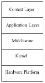
Figure. 2 shows the new context layer which lies above the application layer (usually a classic MVC architecture standard to many legacy embedded applications).
Figure 2: Multi-layer context-aware model
2.1.1 Components
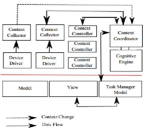
Fig. 3 shows our micro-architecture within the context-aware layer. The components of the micro-architecture are context-collectors, context controllers, a context-coordinator engine and a cognitive engine.
The criteria followed for determining the components in the micro-architecture as well as making the architecture adaptable is taken from Parnas research on rules for module decomposition [17] and software design principles for ease of expansion and contraction [18]. For our basic framework, Parnas stipulates that subsets need to be identified (in our system, contexts) and the idea of information hiding of “secrets” using modules interfaces and definitions (context collectors, context controllers).
Parnas defines “secrets” as design decisions that are likely to change which are located in specialized components (the “on-the-fly” adaptability by expansion and contraction of the cognitive map in the cognitive engine). Parnas also identifies the “uses” structure (requires the presence of) which is reflected in the “requires” functionality of the cognitive map in our system (“requires” functionality “wires” the cognitive map concepts/contexts together to form the map).
Context Collector - The collectors can either interface directly with the sensor device drivers for reading the sensor data or through a hardware abstraction layer. The context-collectors determine a change in context and alert the context coordinator (Fig. 3 and Fig. 4). Context collectors are also responsible for local storage. Storage could potentially reduce expensive energy transmission to improve battery life e.g. by limiting the need for real-time status updates to the server in low battery scenarios. The context collector is separate from the database structure (module) of the model where the general purpose variables are stored.
Context Controller - The context controller is responsible for integrating all the related contexts to produce a meaningful control sequence.
Context Coordinator - The context coordinator engine manages inter-context component and inter-layer messaging. The context coordinator is also responsible for scheduling of tasks.
MVC - The models in Fig. 3 could be physical objects or abstract data structures that are used by the applications. The view model could be a line based display, a graphics display, no display but with output to a hyper-terminal application. The controllers could be responsible for interfacing with hardware peripherals e.g. printers.
Cognitive Engine - The cognitive engine enables dynamic adaptability and is described in detail in Section 2.3.
Figure 3: Proposed Architecture
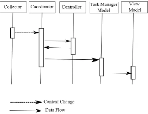
2.1.2 Dataflow
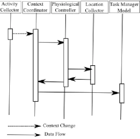
Data flow (Fig. 4) occurs via events (e.g. context changes) and queries. Based on sensor data received (e.g. via interrupts) a determination is made as to whether a context change has occurred. This context change is stored together with other useful environmental variables and the context coordinator engine is notified. At the context coordinator engine level a task or control variable related to the context change is activated. Alternatively, an event is triggered when a timer expires in the context-engine and queries can be sent to context controllers or context-collectors. There are two types of events - implicit and explicit. An implicit event occurs when a change occurs automatically e.g. a car driving to a new area. An explicit event occurs when a context-change occurs deliberately e.g. a new user logs on or vehicle attributes are context-changed or a shift sign-off occurs.
Figure 4: Dataflow sequence diagram for architecture
2.2.Test Cases
The research will preliminarily consider the application of the architecture to three test cases 1) transport dispatching application, Fig. 5 and Fig. 6 2) home-based health monitoring system, Fig. 7 and Fig. 8 and 3) Novax’s Accessible Pedestrian System (APS), Fig. 9.
2.2.1 Transport Mobile Dispatching
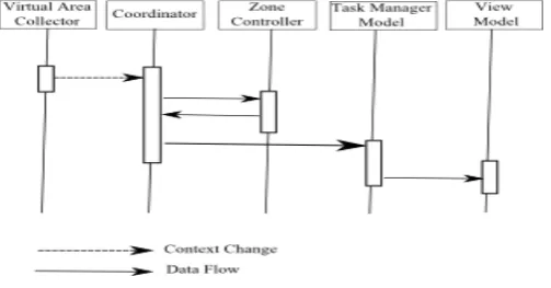
A dispatching application running on a mobile dispatch terminal (embedded system) found in cabs is used for getting customers for taxi-car drivers. Taxi cabs can receive customers via street-hire, auction, reserve, closest cab and stand jobs. Taxis are equipped with GPS are capable of determining the zone that a driver is currently in. As the car moves from zone to zone it is eligible to bid on jobs from that zone, be it auction jobs (left over jobs), reserve jobs (future jobs) or closest cab jobs (current jobs and also dependent on how long the driver has been idle), stand jobs (dependent on proximity to the stand). Jobs are filtered based on driver (multi-lingual) and vehicle attributes (roof rack, lift equipped, minibus etc.), or driver state (active, suspended). The dispatching application architecture and sequence diagram are shown in Figs. 5 and 6.
Model and Controller - Model and Controller functionality could include interfacing with peripherals (camera, debit machine, printer, pager, or modem), system tools models (time, string formatting), and storage models (table data, application data, zone boundary data). View - functionality would be window display (primary job display as well as secondary status and map display).
Context Collector - The sensor context is supplied by the GPS receiver. The virtual area context is the GPS geographically derived area. The application contexts (driver attributes, vehicle attributes, and status) provide software contexts from the server application. Examples of information collected for the status context include job id, taxi status, previous job number, GPS (x,y), stand tokens, number passengers, break count.
Context Controller - The context controller components for the dispatching application are - stands, areas, payment, trip, and time. Tasks performed by the area or stand context controllers are determining current area (shown in Fig. 6), performing bookin operations (stands and zones), handling operational constraints (has the terminal been forced signed off, is there a bid in progress, is there a held auction job/ reserve job, emergency state, number of type of zonal jobs (e.g. soon to clear) allowed).
Context Coordinator engine - Some of the decisions that the context engine perform are the determination of frequency of collection, constraints factors affecting collection e.g. - for status update related information, the effect of dormancy on status updates, co-ordination with the application layer as well as the contextual elements.
Figure 5: Dispatching application architecture
Figure 6: Dispatching application sequence diagram
2.2.2 Home Health Care
A home health care application is used to monitor the elderly. It may comprise a wearable, wirelessly enabled embedded system with sensors which are capable of measuring physiological data. The health-care application architecture and sequence diagram are shown in Fig. 7 and Fig. 8.
Context Collector - The sensor contexts are supplied by the ECG (heart rate context collection), thermistor (temperature context collection), accelerometer (activity context collection), IR (position context collection).
Context Controller -The context controllers are responsible for e.g. generating alarms, logging events.
Figure 7: Dataflow sequence diagram for architecture
Figure 8: Dataflow sequence diagram for architecture
2.2.3 Novax Accessible Pedestrian System
Novax produces accessible pedestrian systems (APS), Fig. 9. A typical scenario is a pedestrian approaches an intersection and pushes the APS’ button, the red led goes on and the button plays "wait to cross." The button receives the walk signal from the traffic controller and plays "walk sign is on." The button receives the flashing don't walk (or ped clear) signal from the traffic controller and plays an audible countdown (10, 9, 8 down to 1).
Figure 9: APS photo courtesy of Novax Industries Corp.
Table 1: Command sequence for actuating controllers
Command Response N1 <x> Insert x into log N2 Display log in entirety N3 Erase log
N4 <mask>
Set specified GPIO on
N5<mask> Set specified GPIO off N6 <x> Turn off led x
N7 <x> Turn on led x
N8 <val> Enable vibe to <val> level N9 <val> Disable vibe
N10 <x> Play sound sequence x N11 Stop sound sequence
This aps firmware application has the following components:
Model - Defines the file manager, timers, configuration utility, logging, manufacturing modes.
Controller - Hardware abstraction layer for the button, uart, spi, led, flash, power line communications, vibe, audio, digital I/O.
Context-Collectors – Variables that track for push button state, pedestrian signal state, audio conflict etc. Each variable is assigned a unique numeric identifier.
Context-Controllers - Command sequence for actuating the controllers directly at an application level. Some commands are listed in Table 1 above.
2.3.Enabling Dynamic Adaptability in the Cognitive Plane
The key feature of the proposed model is to enable firmware adaptability using fuzzy cognitive maps. No previous work has been done on the use of FCMs for enabling dynamic, low memory constrained, firmware adaptability.
FCMs enable adaptable firmware logic by adjusting the strengths of links between concepts (e.g. the context-collector variables change value) or updating the topology of the map by adding, removing concepts (remote update via a supervisor or system operator).
2.3.1 Background Theory – Fuzzy Cognitive Maps
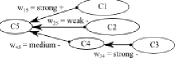
Fuzzy cognitive maps (FCM), Fig. 1 and Fig. 11, model variables or concepts that are interconnected by causal relationships. A causal relationship is defined where a relative change in one concept causes a relative change in a corresponding concept. The type of Fuzzy Cognitive Map used in this research is the Kardaras FCM [19] (uses linguistic weights in decision analysis).
2.3.2 Kardaras Fuzzy Cognitive Maps
In this section the Kardaras FCM functionality is described with respect to assignment of weights, causality and decision analysis. Assignment of Weights - In the Kardaras Fuzzy Cognitive Map [19] model 4 weights are used - Undefined < Weak < Moderate < Strong
Causality - There are 4 causality relationships in Kardaras FCMS - affects, requires, multiples and stops. Only affects, requires (described below) and stops (implied) are relevant to the proposed research model. In Fig. 10 Variable V1 affects Variable V2 and Variable V2 requires Variable V1. Generally, if X affects Y then an increase/decrease X results in an increase/decrease Y. If X requires Y then increase/decrease X does not result in an increase/decrease Y AND an increase/decrease Y required for an increase/decrease X.
Figure 10: Affects and requires causality
Decision Analysis - In the Kardaras model, decision analysis (Equations 1-10) occurs by firstly identifying the causal path I, followed by determining the polarity of the path, the degree of belief and the most believed effect. The polarity of the path S is (+) if the number of negative polarity relationships is even or zero.
The degree of belief of the path φ (phi) is determined by minimum of the fuzzy linguistic weights along the path. The most believed effect ∆ (delta) is path which yields the maximum degree of belief.
Figure 11: Generic fuzzy cognitive map
Using the example presented in Fig. 11 we can identify the different causal paths to get to C5 - I1, I2, I3.
Equations 1-10 also show the results of evaluating polarity S, degree of belief φ and most believed effect ∆ on I1, I2, I3.
I1 = (C1) (1)
I2 = (C2) (2)
I3 = (C4, C3) (3)
S1 = {strong +} = + (4)
S2 = {weak -} = - (5)
S3 = {medium -, strong -} = + (6)
φ1
= strong (7)
φ2
= weak (8)
φ3
= medium (9)
∆ = I1 (10)
2.3.3 Application to Research
In our research we consider a binary FCM with the weights of 0 and 1 instead of weak, medium and strong. φ reduces to the logical AND operation so min (A, B, C) translates to (A AND B AND C). Likewise ∆ reduces to the logical OR operation so max (A, B, C) translates to (A OR B OR C).
For logic map evaluation purposes, φ and ∆ can be used to evaluate multiple variable if/else/else if statements.
Therefore:
if (A AND B) {do x} else if (A AND B’) {do y} else if (A’ AND B) {do z} can be expressed as
max (min (A,B), min(A,B’), min(A’B)) or
∆(φ1, φ2, φ3)
In this form, the basic evaluation building block of our logic map is realized. The format of our logic map is shown in Table 2 below. We additionally introduce the concepts of:
Complement – A variable complement is achieved by using the negative value of the variable i.e. x’ or (NOT x) is expressed numerically as –x.
Latched – Once a path’s φ has been evaluated to 1, 1 is stored in the Latch field of the FCM. Henceforth, this path is always evaluated as having a φ as 1 regardless of the state of the input variables. Regular operation is momentary operation where the path’s φ reflects the real-time evaluation of the input variables.
Timers – If there are two APS buttons working in tandem (typical intersection configuration) it may be required to evaluate the respective APS cognitive engine’s logic simultaneously or on odd rotation. This odd rotation would be achieved by setting the value of the timer field. E.g. if the timer field for APS y is set to 1, the cognitive engine logic would be evaluated on (clock_ticks mod 2) == 1, if the timer field for APS z is set to 0, the cognitive engine logic would be evaluated on (clock_ticks mod 2) == 0. A real-time example would be to have APS y play one sound and APS z play the subsequent sound e.g. APS y plays 1,3,5,7 of the audible count-down and APS z plays 2,4,6,8 of the audible countcount-down.
Table 2: Logic Map Fields
Field Id Data 1
Coverage map line number 2
Number of variable to be evaluated 3-4
Unique variable id 5
Timer 6
Momentary/Latch 7
Calculated phi for this path 8
Determined latch 9-16
Context controller command sequence
3.Method
This section describes the implementation and latency evaluation procedure of a simplified subset of the dispatching application (Section 2.2.1) and the cognitive engine for the APS system (Section 2.2.3).
3.1.Dispatching Application and Latency
A simplified subset of the dispatching application outlined in Section 2.2.1 and Figs. 5 and 6 was profiled. The details (procedure calls, messaging) are described in Section 4.2. This subset was used to evaluate the latency introduced by the extra layers of the context-collectors/context-coordinators/context-controllers in the new architecture and compared against a standard MVC architecture implementation. The code was written in C and preliminarily verified on an x86 (DOS) platform.
The source code is available upon request. The scenario profiled was the case where gps context data is used to evaluate the zone the vehicle is currently in. The sequence diagram for this test case in the new architecture is shown in Fig. 6 and the sequence diagram for older MVC architecture is shown in Fig. 17. The system model in the older architecture (Fig. 17) is replaced by the context-collector, context-coordinator and context controller models (Fig. 6) in the new architecture.
There are several state-of the art tools available for latency model evaluation. The one chosen for this project was Rapita RVS (Rapid Verification Suite) [22].
Performance analysis of this proposed research model was confined to source code simulations as opposed on-target verification. On on-target timing would be the same as the simulation because there was no operating system or multi-threaded application. Rapita's Rapitime works by instrumenting the source code during the preprocessor build stage in order to enable execution of performance analysis and generate a report on the subsequent trace data (Fig. 18, Fig. 19).
The types of performance analysis undertaken by Rapitime include:
• Worse Case Execution Time (W-ET)
• Maximum Execution Time (M-ET)
• High Water Mark Execution Time (H-ET)
• Execution Time Profiles
The Execution Time profiles are further divided into Self Execution Time (SelfET), Sub Routine Execution Time (SubET) and Overall Execution Time (OverET). Additional analysis is provided with respect to Test coverage, Loop bounds, Call Trees and Context Information. Using the Rapita tool, the code analysis results were simulated using an ARM processor engine.
Figure 16: The RVS process, Rapita©
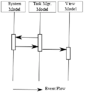
Figure 17: Standard MVC architecture
3.2.APS Cognitive Engine
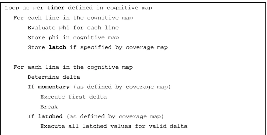
The APS cognitive engine was written in C and preliminarily verified on Microchip ™ PIC 18F series (MCU 8-bit, 128 KB Flash) embedded processor. The φ and ∆ state diagram are shown in Figs. 12 and 13 respectively. The pseudo code for the cognitive engine is shown in Fig. 14. The source code for the cognitive engine (only) is available upon request.
Figure 12: FCM φ state-diagram
Figure 13: FCM ∆ state-diagram
Figure 14: Pseudo code for cognitive engine
The test scenario involves defining different logic for different values of audio conflict and stuck button occurring together. Table 3 describes the functionality we want to implement, where depending on the value of the context-collector variables either the led is turned off, or the vibe is turned off or an error condition is logged. An audio conflict is a sound playing in the wrong pedestrian state e.g. a walk sound playing during the don’t walk pedestrian state.
We define the following context collectors - BAC is button audio conflict where 1 is audio conflict detected and 0 is no audio conflict detected. BS is stuck button where 1 is stuck button detected and 0 is no stuck button detected. The context collectors are program variables that have unique identifiers, BAC id is 1 and BS id is 2.
Table 3: Logic Map Setup
BAC BS Action Logic Coverage Map Entry 1 1 Turn off led 1 2 1 2 0 0 0 0 'N' '6' '0' 0 0 0 0 0 0 1 Turn off vibe 3 2 -1 2 0 0 0 0 'N' '9' 0 0 0 0 0 0 1 0 Log error 9 2 2 1 -2 0 0 0 0 'N' '1' ' ' 'e' 'r' 'r' ' ' '9'
In order to rapidly prototype the proof of concept, simulated commands for updating the coverage map and manually overwriting the value of the context collectors via a Tera-term terminal utility were used. (This is instead of incorporating the coverage map logic download into the Novax APS configuration utility which is generally to change user parameters e.g. sounds, volume levels). The context coordinator was configured to run the cognitive engine once instead of continuously on a periodic timer. The input command sequence is shown in Table 4 and the results are shown in Fig. 15
Loop as per timer defined in cognitive map
For each line in the cognitive map
Evaluate phi for each line
Store phi in cognitive map
Store latch if specified by coverage map
For each line in the cognitive map
Determine delta
If momentary (as defined by coverage map)
Execute first delta
Break
If latched (as defined by coverage map)
Execute all latched values for valid delta
Table 4: Input command sequence for testing cognitive engine
Input Command Sequence
Expected Result
V0 000 Initialize all context collector variables to zero V1 Load logic coverage map line 1
V2 Load logic coverage map line 2 V3 Load logic coverage map line 3
V0 111 Force values BAC=1, BS=1 to execute V1 context controller commands V0 101, N3,
N2
Force values BAC=0, BS=1 to execute V2 context controller commands, delete, display log
V0 110, N2 Force values BAC=1, BS=0 to execute V3 context controller commands, display log
4.Results
In this section the latency results are compared for our architecture versus the standard MVC architecture. Also the results of the APS cognitive engine operation are presented.
4.1.Latency Results
Figures. 18 and 19 show the key routines associated with the new architecture coord_main call tree and the old architecture sys_main call tree. The call tree lists the number of functions defined as well as the order in which they are called (which gives insight into the messaging sequence (shown in Figs. 6 and 17.)) The new architecture has 9 functions and the old architecture has 5 functions. Fig. 18 also shows a detailed listing of the latencies in execution cycles. In the new architecture the context coordinator (coord_main) queries the context collector (coll_context_change) for gps data (gps_get_serial_data) from the gps driver (gps_driver). The context-coordinator then passes this data (coord_handle_communication) to the zone context controller which processes it and then notifies (zone_handle_communication) the context coordinator of the zone. The context coordinator then notifies (coord_handle_communication) the task manager of the zone information which passes the information (tsk_handle_communication) to the windows display controller (wnd_update). In the old architecture sys_main is responsible for querying the gps (gps_get_serial_data, gps_driver) and determining the zone, after which the task manager is notified ((tsk_handle_communication)) which forwards the information onto the windows display (wnd_update). From the simulation it was shown that the benchmark statistics for Overall Execution Times are the same for the new and old architectures, i.e. Min OverET, Average OverET, High Water OverET, Max OverET, Worse Case OverET are identical. For latency analysis the Worse Case Execution Times are used.
Overall Latency - In this research overall latency is defined as the sum of functional latency, abstraction latency and messaging latency. The overall latency in the new architecture is larger.
coord_main requires an overall execution time (OverET) of 8216 execution cycles and sys_main has a 4579 OverET. The increased latency is because of additional overhead in contextual processing.
Functional Latency - The core logic functionality latency is assumed to be the same for both the new and old architectures as the core logic is only organized differently.
Abstraction Latency - Overall the abstraction latency is larger in the new model. From Fig. 18 the new model has the additional coll_context_change routine with 1757 SelfET, in addition to the routines shared with the old architecture gps_get_serial_data, gps_driver, and wnd_update.
Messaging Latency - The messaging latency is larger in the new model because there are more components and there is communication between the components and between the context layer and the application layer. From Fig. 18 the new model has the additional coord_handle_communication 2436 SelfET,
zone_handle_communication (not profiled) and send_inter_model_message 1299 SelfET. The routine shared with the old architecture is tsk_handle_communication 1155 SelfET.
Figure 18: Rapita simulation results
Figure 19: Rapita worse case execution profile
4.2.Cognitive Engine Result
The results in Fig. 15 show the correct operation of cognitive engine for interpreting and executing the logic map. As per Table 4, rows 1-7 were entered sequentially at Terra-term and the results displayed. The code is written such that the command currently being executed is also displayed to the terminal e.g. N6 is shown on the screen when the led is turned off, N9 appears when the vibe is turned off. Observing the APS hardware shows corresponding physical outputs also being actuated. When the contents of the BAC and BS variables are updated or the logic map is updated a confirmation of the contents is also printed to the screen. Before [V0 110] is evaluated the log is deleted and then displayed to verify 0 events logged. After [V0 110] is executed the log contents show error code 9 registered.
Figure 15: Results displayed on terminal program (Tera-term
>V0 000
VAR = 0 0 0
> V1
1 = 1 2 1 2 0 0 0 0 86 122 48 0 0 0 0 0
> V2
2 = 2 2 1 -2 0 0 0 0 76 109 32 101 114 114 32 57
> V3
3 = 3 2 -1 2 0 0 0 0 86 118 0 0 0 0 0 0
> V0 111
VAR = 1 1 1 > N6
> V0 101
VAR = 1 0 1 > N9
Vibe off > N3 > N2
0,*,01/01/01,00:02:31,,Log started,3 0 events
> V0 110
VAR = 1 1 0 > N1 err 9 > N2
0,*,01/01/01,00:02:31,,Log started,3 0,*,01/01/01,00:02:42,a,*** Marker ***,9 1 events
5.Discussion
In this section the new model will be evaluated for code size (footprint), latency and code complexity as well as a discussion on the advantages and disadvantages of our model, future work and concluding remarks.
5.1.Code Size
The cognitive engine functionality is designed to be used with micro-processors with low memory requirements. Our Novax APS test-bed has 128KB flash memory. The size taken up by the cognitive engine is 138 bytes, φ function is 246 bytes and ∆ function is 76 bytes. The code real-estate used to achieve dynamic adaptability is very small.
5.2.Code Complexity
The cognitive engine can be evaluated for code complexity using the McCabe Cyclomatic Complexity Metric. This metric measures complexity with respect to the number of linearly independent paths in the source listing. Dynamic allocation of the logic maps reduces the number of hard-coded paths. Only the logic that is needed is built into the map. There is no catch-all functionality which would significantly increase the number of linearly independent paths and consequently increase code complexity [21]. The use of FCM reduces the overall code complexity.
5.3.Advantages and Disadvantages
Based on the above findings, the advantages of our system include the light-weight FCM design characterized by low code space and reduced complexity. None of the previous works from Section 1.2 were developed to operate under such constrains. Our design can be scalable limited to only the memory space available on the processor and the number of context controllers and context collectors defined. The proof of concept introduced limitations on logic map size only for rapid prototyping purposes. Our logic map design allows for more free-form changes with greater control over the device and it is not limited to e.g. specific predefined plans as used by Gamez [5]. The disadvantages of our research include limitations on the complexity of the logic map operator feature set e.g. it currently cannot support sophisticated machine learning algorithms or advanced mathematical operations. Another drawback is the end user needing application specific knowledge e.g. the context collector variables unique identifier numbers. This direct access to program variables may also pose security issues. The logic map design is based on the use of cyclic executive timing (or time slices) and not for use with a real-time operating system as there is no provision for mutexes to mitigate deadlocks or race-conditions.The increased architecture latency is not significant enough to be prohibitive to the solution’s adoption.
6.Conclusion
The purpose of the research was to develop a context-aware embedded firmware model for dynamic adaptability.
Simple well organized modularized components in a context-aware layer which resides above the application layer accomplished this. Dynamic adaptability was achieved using Fuzzy Cognitive Maps in order to provide user configurable logic for a flexible and enhanced application operation. The proposed research model was shown to be suitable for use with resource constrained embedded processors found in either wireless sensor networks or mature or legacy or cost-aware applications with single core processors.
7.Recommendations
While our research was developed for and is recommended for use in resource constrained embedded systems, because of its light-weight design it can also be used with more complex multi-core, multi-media, embedded processors or desktop or sever solutions. Our design, where the context-aware functionality is layered above a standard MVC architecture, easily extends existing solutions built on a standard MVC architecture. The FCM cognitive engine can be used to change user functionality depending on the customer needs, time of day, or special occasion (e.g. in the APS case, heavier pedestrian traffic flow during public festivals requiring one-of, infrequent operational change).
Our recommendations for further research includes the development of a formal SDK (system development kit) for the context-aware adaptable architecture similar to Dey’s tool-kit [5], expanding the cognitive logic map to be more that 16 characters per line by using variable length fields, exploring multi-line context controllers, and investigating compression techniques for context-controller command sequences, incorporating a checksum (for wireless download), providing an expanded instruction set to augment our phi, delta, latch, momentary complement and timer functionality (potentially based on research into the current range of FCM operators) and expanding from a binary to ternary or n-ary FCM. In our example the maps were stored in RAM variable space but they can also be stored in external, peripheral flash.
Acknowledgements
The authors would like to thank CMC Microsystems Inc. for facilitating access to and support for the Rapita tool suite. CMC Microsystems Inc. a not-for-profit organization supporting Canadian microelectronics and micro-devices research. And Novax Industries Corporation for use of their APS staging system.
References
[1] C. Jaggernauth, B. Hung, P. Lin, Y. Chuo, B. Kaminska, “Test Firmware Architecture for a Flexible Wireless Physiological Multi-Sensor.” IEEE International Conference on Man, Systems and Cybernetics, Oct. 2011.
[2] C. Jaggernauth, B. Hung, P. Lin, Y. Chuo, B. Kaminska, “Optimized, Practical Firmware Design For a Novel Flexible Wireless Multi-Sensor Platform for Body Activity And Vitals Monitoring.” IEEE International Conference on Consumer Electronics, pp 551-552, Jan. 2011.
[3] K.B.R.G.T. Samarasinghe, M.M.N.N. Jayasekara, D. Elkaduwe and R.G. Ragel, “Power Aware Instruction Scheduling for Microcontrollers,” International Journal of Scientific and Research Publications, vol. 2(10), October 2012.
[4] Armoush Ashraf. “Design Patterns for Safety-Critical Embedded Systems.” Ph.D. thesis, RWTH AAChen, Germany, 2010.
[5] A.K. Dey, G.D. Abowd and D. Salber, “A conceptual framework and a toolkit for supporting the rapid prototyping of context-aware applications.” Hum.-Comput. Interact, vol. 16-2, pp 97-166, 2001.
[6] N. Medvidovic, “Software Architectures and Embedded Sytems: A Match Made in Heaven.” IEEE Software, September/October 2005.
[7] P. Inverardi and M. Tivoli, “The Future of Software: Adaptation and Dependability.” ISSSE 2006-2008, LNCS 5413, Springer-Verlag Berlin, Heidelberg, pp 1-31, 2009.
[8] N. Gamez et al., “Context-Awareness in Wireless Sensor Networks: A Middleware Solution.” Sensors, 2012.
[9] C. Jaggernauth, “Modeling Returned Biomedical Devices in a Lean Manufacturing Environment,” in Computational Models of Complex Systems, Intelligent Systems Reference Library, Springer, 2014, Chapter 8.
[10] G. Buyukozkan and Z. Vardaloglu, “Analyzing of collaborative planning, forecasting and replenishment approach using fuzzy cognitive map.” International Conference on Computers and Industrial Engineering, 2009.
[11] F. Mastrogiovanni, A. Scalmato, A. Sgorbissa, “Affordance-Based Planning for Assisting Humans in Daily Activities.” Sixth International Conference on Intelligent Environments (IE), 2010.
[12] D.K. Iakovidis and E. Papageorgiou, “Intuitionistic Fuzzy Cognitive Maps for Medical Decision Making.” IEEE Transactions on Information Technology in Biomedicine, Jan 2011.
[13] E.I. Papageorgiou, N.I. Papandrianos and D. Apostolopoulos, P. Vassilakos, “Complementary use of Fuzzy Decision Trees and Augmented Fuzzy Cognitive Maps for Decision Making in Medical Informatics.” International Conference on BioMedical Engineering and Informatics, BMEI 2008.
[14] E. Papageorgiou et al., “A Fuzzy Cognitive Map based tool for prediction of infectious diseases.” FUZZ-IEEE, 2009.
[15] G. Krasner and S. Pope, “A Cookbook for Using the Model-View-Controller User Interface Paradigm in Smalltalk -80.” Journal of Object Oriented Programming (JOOP), August/September 1988.
[16] S. Pantsar-Syvaniemi, “Architecting Embedded Software for Context-Aware Systems,” in Embedded Systems - Theory and Design Methodology, InTech, 2012.
[17] D.L. Parnas, “On the criteria to be used in decomposing systems into modules.” Commun. ACM, vol. 15(12), pp 1053-1058, 1972.
[18] D.L. Parnas “Designing software for Ease of Extension and Contraction.” IEEE Trans. Software Eng, vol. 5(2), pp 128-138, 1979.
[19] D. Kardaras and B. Karakostas, “The use of fuzzy cognitive maps to simulate the information systems strategic planning process.” Information and Software Technology, 1999.
[20] M. Hamilton, “Software Development: A Guide to Building Reliable Systems.” Prentice Hall, 1999.
[21] T. McCabe, “A Complexity Measure.” IEEE Transactions on Software Engineering, vol. 2, no. 4, 1976.
[22] Rapita. RapiTime. Internet: http://www.rapitasystems.com/products/RapiTime, [May 20, 2015].