Research Article
1
A Virtual Channel Allocation Algorithm for NoC
Dongxing Bao
1, Xiaoming Li
2,*, Yizong Xin
3, Jiuru Yang
1, Xiangshi Ren
4, Fangfa Fu
2and Cheng Liu
21School of Electronic Engineering, Heilongjiang University, Harbin 150080, China
2Dept. of Microelectronics Science and Technology, Harbin Institute of Technology, Harbin 150001, China 3School of Information Engineering, Shenyang University of Technology, Shenyang 110870, China 4School of Information, Kochi University of Technology, Kochi 780-8520, Japan
Abstract
Virtual channel (VC) flow control proves to be an alternative way to promote network performance, but uniform VC allocation in the network may be at the cost of chip area and power consumption. We propose a novel VC number allocation algorithm customizing the VCs in network based on the characteristic of the target application. Given the characteristic of target application and total VC number budget, the block probability for each port of nodes in the network can be obtained with an analytical model. Then VCs are added to the port with the highest block probability one by one. The simulation results indicate that the proposed algorithm reduces buffer consumption by 14.58%~51.04% under diverse traffic patterns and VC depth, while keeping similar network performance.
Keywords: VC allocation, block probability, network-on-chip
Received on 12 August 2017, accepted on 28 September 2017, published on 28 August 2017
Copyright © 2017Dongxing Baoet al., licensed to EAI. This is an open access article distributed under the terms of the Creative Commons Attribution licence (http://creativecommons.org/licenses/by/3.0/), which permits unlimited use, distribution and reproduction in any medium so long as the original work is properly cited.
doi: 10.4108/eai.28-8-2017.153307
*Corresponding author. Email: [email protected]
1. Introduction
SoC designs are confronted with various challenges caused by the increasing complexity of the designs [1]. The on-chip communication bandwidth requirement is growing rapidly, and simultaneously the interconnect delay exceeds the average on-chip clock period [2]. Network-on-chip (NoC)
which replaces bus with network to implement the communication among processing elements (PE) has been proposed [3,4], and becomes one of the most promising
on-chip interconnection architectures [5]. NoC is composed of
Network Interface (NI), Router, and Link basically. Compared with traditional on-chip bus, NoC has many advantages—reusability, scalability, parallelism, etc, which satisfies future SoC interconnection requirements [3-5].
The benefits of NoC are attractive, but attaining their full potential will present lots of challenges among which power consumption stands out as one of the most critical challenges[5]. Since router is one of the kernel components
of NoC and it has significant influence on both the
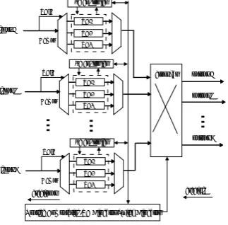
performance and power consumption of NoC[6], we mainly focus on it in this paper. A typical virtual channel router structure is shown in Figure.1. It is composed of Routing Computation (RC), VC Allocator (VA), Switch Allocator (SA), VC, crossbar, and Mux as well as Demux. Among the five parts of router, VC has prominent effect on router. However, VC takes up most of the power and area consumption of router[7], especially more than sixty percent
of the static power consumption[8,9]. On the other hand, VC
number and capacity determines the router performance with specific router architecture. With more VCs and larger capacity, data in the network will be able to forward to the destination node more fluently, while under the opposite situation, the network are prone to get blocked and saturated. To get out of such a dilemma, the researchers proposed many strategies from diverse points of view. The authors of
[10,11] introduce power gating to shut down idle VCs.
Although power gating can reduce the system static power consumption, it needs additional technology support. What’s worse, the static power saving will decrease greatly under heavier workload. The authors of [12,13] propose dynamic
on
Ambient Systems
EAI Endorsed Transactions on Ambient Systems
2
buffer allocation strategy adjusting the VC number or depth based on network status. The strategy can be effective in diverse traffic; however, the designs are usually complex and result in additional hardware consumption. Therefore little power saving can be achieved when the data width is not very large. It is tough to find out a general method to make compromise on performance and power consumption.
credit in
Routing Computation/VC Allocator/Switch Allocator
output E
output N
output L
credit out
VC1
VC3 VCID
Demux
input E VC2 vc controller
VC1
VC3 VCID
Demux
input N VC2 vc controller
VC1
VC3 VCID
Demux
input L VC2 vc controller
crossbar
Figure 1. A general virtual channel router architecture
NoC design typically aims at certain specific application, thus the NoC architecture can be customized to specific application to obtain the best design trade-offs[14]. Taking
this matter into consideration, Hu et al work out an analytical performance model for NoC, and then proposed a buffer capacity allocation algorithm based on the performance model[7]. According to the algorithm, the buffer
with the highest full probability is assigned larger buffer capacity. However, such an allocation algorithm is limited to router with single buffer channel. Consequently, when it comes to higher throughput requirements application, router based on VC is necessary and the algorithm will be not available. To remedy this situation, Ting-Chun Huang et al.
[15] develop a VC planning algorithm. The algorithm only
adds VCs to channels which present the highest bandwidth usage. Although the algorithm presents prominent power savings when the VC is deep, it doesn’t work well when the VC is shallow. In fact, the probability due to feedback of VCs in the next router can’t be ignored, especially when the VCs are shallow. In this paper, a novel VC number allocation algorithm is proposed. Taking both arbitration contention and VC feedback probability into account, we add VCs to port with the highest block probability.
2. Buffer Utilization Characteristic for NoC
To get a better view of VC utilization characteristic in NoC, we make a stat. of VC utilization under hotspot traffic with a cycle accurate SystemC simulator. X-Y routing algorithm is adopted in a 4x4 2D Mesh NoC. And there are three four-flit-VCs in each input port of the router. Average injection rate is 0.3 flit/node/cycle and the hotspot locates in (2, 2).
The simulation begins with a warm-up period of 100000 cycles. Then performance data is collected 100000 cycles later. Figure.2-(a) shows the buffer utilization in different ports of different nodes. It is obviously that the buffer utilization of different nodes differs notably. Even buffer utilization in the same node varies significantly. The lowest buffer utilization in the network is 0.0053, while the highest is 0.427 and it is 80 times higher than the lowest! Figure.2-(b) indicates the buffer utilization under uniform traffic. It is amazing that buffer utilization differs greatly even under uniform traffic. The highest buffer utilization is 0.0562, which is about 8 times higher than the lowest.
(1,1) (1,2) (1,3) (1,4) (2,1) (2,2) (2,3) (2,4) (3,1) (3,2) (3,3) (3,4) (4,1) (4,2) (4,3) (4,4) 0
0.05 0.1 0.15 0.2 0.25 0.3 0.35 0.4 0.45
Ports of Different Nodes
A
ve
ra
g
e
B
u
ff
e
r
U
til
iz
a
tio
n
(a) Traffic with Hotspot
(1,1) (1,2) (1,3) (1,4) (2,1) (2,2) (2,3) (2,4) (3,1) (3,2) (3,3) (3,4) (4,1) (4,2) (4,3) (4,4) 0
0.01 0.02 0.03 0.04 0.05 0.06
Port of Different Nodes
A
ve
ra
ge
B
uf
fe
r
U
til
iz
at
io
n
(b) Uniform
Figure 2. VC utilization of different ports in each node
The simulation results illustrate that unbalance of buffer utilization exits in diverse traffic patterns including uniform traffic. The main reason is 2D Mesh topology as well as X-Y deterministic routing. In fact, the application characteristic, routing algorithm, topology etc have notable effect on buffer utilization in network. Therefore, unbalanced buffer utilization in NoC is usual. As buffer utilization varies across the network, with uniform VC allocation, VCs in some ports might be idle and wasted, while VCs in some other ports might be insufficient and a mass of data might be blocked. Hence customizing the VCs configuration in NoC based on the application characteristic will decrease buffer consumption through reducing superfluous VCs and alleviate block by adding VCs. At the
EAI Endorsed Transactions on Ambient Systems
3 same time, the network performance can be maintained or even improved.
3. Static Virtual Channel Number
Allocation
3.1. Basic Idea
To fully utilize the limited VCs in the network and satisfy the performance requirements with the least VCs, VCs are allocated across the network based on needs of the ports. But the problem is how to define the needs of ports in the network. To make the problem clear, we explain how the data is transmitted in a router first. Router receives and stores data injected from the input ports. When the data in the VCs gets through the Mux, and there are available VCs in the next router, it sends request to VA. With the grant of VA, it still needs to make sure that the assigned VC is not full before the data sends request to SA for the output port. With the grant of SA, the data will be sent to crossbar and then leaves from the output port. All the data that fails to request or be granted by VA or SA is stored in VCs of current router. In other words, all the data that is blocked will be stored. The higher the block probability is, the more data needs to be stored and the worse the performance is. Therefore alleviating the block probability will be one of the possible ways to improve the network performance.
The root of block is limited bandwidth of the link and limited buffer capacity of the router. Generally speaking, the bandwidth of the link is fixed. Under this situation, especially when the link bandwidth of the link is sufficient, we have to turn to the buffer capacity. Buffer is used to smooth the injection rate and the ejection rate of the router. Increasing buffer capacity of the corresponding port in the next router will alleviate the block probability and increase the ejection rate. As buffer capacity is limited, we only increase VCs where the block probability is high. As a result, there are fewer VCs where the block probability is low. However, when the link becomes saturated, adding VC will bring few benefits. On the opposite, the hardware consumption increases. So VC number in each port will be limited. Therefore we develop a VC allocation algorithm based on block probability. Compared with uniform VC configuration, the buffer consumption is reduced significantly, while achieving similar performance. The analytical model of the blocking probability and VC number allocation algorithm will be described in detail below.
3.2. Problem Formulation
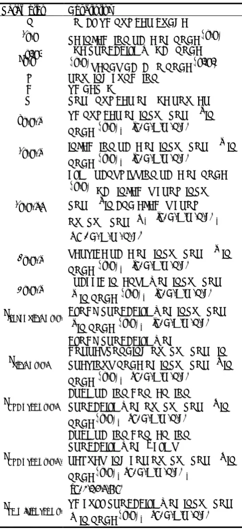
For convenience, the notations used in analysis are listed in Table 1. And the problem of VC number allocation can be formulated as follow.
Assume:
PE injects packet with a Poisson distribution. Given:
Total VC number budget, S
Application communication characteristic, x y, and ,
,
x y Px y
Routing algorithm, R
Virtual channel depth, D
Table 1. Parameter Notion
Parameter Description
S TOTAL VC NUMBER BUDGET
,
x y
PE INJECTION RATE OF NODE
x y, ,,
x y
Px y THE PROBABILITY THAT NODE
x y, SENDS DATA TO NODE
x y ,
R ROUTING FUNCTION
D VC DEPTH
U PORT NUMBER OF THE ROUTER
, ,
vx y j VC NUMBER OF INPUT PORT jIN
NODE
x y, ,j E N W S L
, , , ,
, ,
x y j
INJECTION RATE OF INPUT PORT j IN NODE
x y, ,j E N W S L
, , , ,
, , ,
x y j k
FLIT TRANSMISSION RATE OF NODE
x y, THAT INJECTS FROM INPUTPORT jIN AND EJECTS FROM OUTPUT PORTk,j E N W S L
, , , ,
,
, , , ,
k E N W S L
, ,
x y j
SERVICE RATE OF INPUT PORT j IN NODE
x y, ,j E N W S L
, , , ,
, ,
x y j
TRAFFIC INTENSITY OF INPUT PORT
j IN NODE
x y, ,j E N W S L
, , , ,
_ _ , ,
input block x y j
P BLOCK PROBABILITY OF INPUT PORT jIN NODE
x y, ,j E N W S L
, , , ,
_ , ,
block x y k
P
BLOCK PROBABILITY OF
CORRESPONDING OUTPUT PORT IN PREVIOUS NODE OF INPUT PORTkIN NODE
x y, ,k E N W S L
, , , ,
_ _ , ,
ARB con x y k
P ARBITRATION CONTENTION PROBABILITY OF OUTPUT PORT kIN
NODE
x y, ,k E N W S L
, , , ,
_ _ , , ,
ARB con x y k n
P
ARBITRATION CONTENTION PROBABILITY OF nFLITS
REQUESTING FOR OUTPUT PORT kIN NODE
x y, , k E N W S L
, , , ,
,
0,1,2,3,4,5
n
_ _ _ , ,
VC full con x y k
P VC FULL PROBABILITY OF INPUT PORT k IN NODE
x y, ,k E N W S L
, , , ,
EAI Endorsed Transactions on Ambient Systems
4
Determine:
VC configuration vx y j, ,
Which minimizes average network latencyLat Min(Lat) s. t. vx y j, , S
x y j
(1)
3.3. Block Probability Analysis
For convenience, single VC is configured in each input port. x y j N E S W L, , { , , , , } , vx y j, , 1 . With previous analysis, it is natural that the block probability is consist of two aspects—arbitration probability including VA and SA and VC feedback probability. Therefore Pblock x y k_ , , can be derived:
_ _
_ _ _ , ,
_ , , 1 1 ARB con x ,y ,k 1 VC full con x y k
block x y k
P P P
(2) Node
x y ,
indicates the node that connects with input port k in node
x y, ,and kis corresponding output port in node
x y ,
.When more than two flits request for the same output port k , there is an arbitration contention. Then the arbitration contention probability is:
_ _ , , ,
2
ARB_con_x,y,k ARB con x y k n
U
P P
n
(3)
_ _ , , , 1 , , , 1 , , ,
, , 1, , , ,
1 , , 1, 1 , , ,
ARB con x y k n
P x y E k x y j k
x y j k x y j n k n
x y j n k x y L k
(4) , , , , , { , , , , }
x y j x y j k
k N E S W L
(5)
, , , , , , , , , , , , ,x ys s xd yd
R x y x y x y j k x y j k s s d d x ys s
(6)
, , , , , , ,
R x y x y x y j ks s d d indicates the routing algorithm.
When there is data transmitted from source node
x ys s,
to destination node
x yd d,
, and the data is injected from input port j of node
x y, and leaves from output k of node
x y, , Rreturns 1, or else it returns 0.The full probability of VC can be calculated with M/M/1/K queuing model.
, ,
_ _ _ , , 1
, ,
1
1 D x y k
VC full con x y k D
x y k
P (7)
Node
x y ,
is the node that corresponds to output portk of node
x y, , and k is the corresponding input port ofnode
x y ,
.Without block, the service rate is 1. Thus the service rate of the queue can be approximated:
_ _ , ,
, , 1 input block x y j
x y j P
(8)
_ _ , , , , , _ _ , , ,
1
input block x y j output block x y j k
N
P Px y j k P
k
(9)
_ _ , , ,
{ , , , , }, , , ,
output block x y j k
i N E S W L i j
P x y i k
(10) { , , , , } , , , , , , , , , i N E S W L
x y j k Px y j k
x y i k
(11) Then the traffic intensity of the queue is:
/
, , , , , ,
x y j x y j x y j
(12) When there are multiple VCs in ports of the router, as an output port won’t be blocked before all the VCs are blocked. Therefore, Pblock x y k_ , , can be approximated:
_ _ , , _ _ _ , ,
_ , ,
, , 1 1 VA con x y k 1 VC full con x y k block x y k
vx y k
P P P
(13) Node
x y ,
indicates the node that connects with input port k in node
x y, ,and kis corresponding output port in node
x y ,
.3.4. VC Number Allocation Algorithm
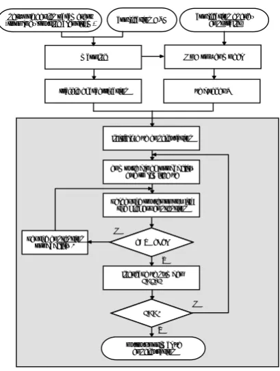
As shown in Figure.3, an effective greedy algorithm based on the aforementioned block probability model is proposed.
Given the design parameters (topology, routing algorithm and so on) and Communication Task Graph (CTG), the network scale and traffic characteristic can be acquired with mapping. At the same time, VC budget can be derived from power budget of the target application with NoC power model. Then the VC number allocation begins. First of all, the number of VCs in each port is initialized to one. Then the block probability of each output port can be calculated to find out the port with the highest block probability. If the VC number in the corresponding input port is equal to the upper VC limitmax_vc, set the block probability zero and search for the next candidate. Or else, add a VC to the input port, and decrease by one from the total VC budget. Iteration restarts as long as the VC budget is still available. When the process stops, the VC configuration is derived.
max_vc is greatly influenced by the topology, packet
length, traffic characteristic, VC number and depth, routing algorithm and son on, so it is almost impossible to determine with an analytical model. With specific simulation environment, we add VC uniformly. When the performance won’t be improved notably, the VC number in each port is
max_vc. max_vc used in this paper is four.
EAI Endorsed Transactions on Ambient Systems
5
Y N
N
Y mapping
traffic charactrization
initialize vc configuration
compute block probability due to limited vc
select the router port with the highest contention
set the contention probability 0
increase vc number
S=S-1
v<max_vc
S==0 network design parameters
(topology,routing algorithm) application CTG
output optimal vc configuration
application energy constraint
NoC power model
vc budget S
Figure 3. VC allocation algorithm flowchart
4. Simulation and Analysis
The simulation environment is based on a cycle-accurate, flit-level SystemC simulator.
During simulation, the data packets are yielded by a Poisson process at a definite traffic rate from the source PEs. 10000 packets are injected into each node and all the performance is abstracted after 100000 warm-up cycles. Detailed simulation condition is listed in Table 2. Besides, V0-NoC, V1-NoC and V2-NoC respectively indicate NoC with uniform VC allocation, NoC with VC allocation algorithm proposed in [15] and NoC with VC allocation algorithm proposed in this paper.
Table 2. Experiment Condition
Topology 2D Mesh
NETWORK SCALE 4X4 TEMPORAL
DISTRIBUTION
POISSON PACKET LENGTH 8
VC DEPTH 4, 8, 16
FLIT WIDTH 64 BIT
ROUTING ALGORITHM X-Y DETERMINISTIC ROUTING
ARBITRATION ALGORITHM
ROUND ROBIN
FLOW CONTROL WORM-HOLE
Table 3~5 exhibit the average network latency when the VC depth is 4, 8, 16 respectively under diver traffic. It
indicates that the system benefits from customizing VC configuration with both allocation algorithms under almost all the traffic patterns. Buffer consumption can be reduced by 14.58%~51.04% under diverse traffic patterns and VC depth, while keeping similar network performance. However, Compared with the algorithm proposed in [15], the algorithm developed in this paper achieves 4.17%~42.71% more buffer savings when the VC depth is 4. And it still performs better basically when the VC depth is 8. While when the VC depth is 16, the two algorithms acquire similar buffer savings. The reason for this is that the algorithm proposed in [15] doesn’t take VC depth into consideration. In fact, when the VC is shallow, the block probability due to feedback of VC has notable influence on network performance. When the VC gets larger, the feedback probability can be ignored, therefore the two algorithms perform similar.
Acknowledgements.
This work has been supported by the Research Funds of Education Department of Heilongjiang Province, Grant No. 12531518.
References
[1] Ho, R., Mai, K. and Horowitz, M. (2001) The Future of Wires. Proc. IEEE. 89(4):490-504
[2] Dally, W. J. and Towles, B. (2001) Route Packets, Not Wires: On-Chip Interconnection Networks. In Proceedings of The 38th Design Automation Conference, Las Vegas, USA, 18-22 June, 2001(New York, USA:ACM):684-689
[3] Benini, L. and Micheli, G. D. (2002) Networks on Chips: A New SoC Paradigm. IEEE Trans. on Computers, 35(1):70-78 [4] Guerrier, P. and Greiner, A. (2000) A Generic Architecture
for On-Chip Packet-Switched Interconnections. In
Proceedings of Design Automation and Test in Europe (DATE'00), Paris, France, 27-30 March, 2000(Paris, France:IEEE):250-256
[5] Bjerregaard, T. and Mahadevan, S. (2006) A Survey of Research and Practices of Network-on-Chip. ACM Computing Surveys, 38(3):1-51
[6] Kim, J., Nicopoulos, C., Park, D. et al. (2006) A Gracefully Degrading and Energy-Efficient Modular Router Architecture for On-Chip Networks. In Proceedings of The 33rd International Symposium on Computer Architecture (ISCA’06), Boston, USA, 17-21 June, 2006 (Boston, USA: IEEE):4-15
[7] Hu, J. and Marculescu, R. (2004) Application-Specific Buffer Space Allocation for Networks-on-Chip Router Design. In
Proceedings ofThe IEEE/ACM International Conference on Computer Aided Design (ICCAD), San Jose, USA, 07-11 November, 2004(Washington, USA:IEEE):354-361
[8] Nicopoulos, C. A., Park, D., Kim, J. et al. (2006) VichaR: A Dynamic Virtual Channel Regulator for Network-on-Chip Routers. In Proceedings of The 39th Annual IEEE/ACM International Symposium on Microarchitecture, Orlando, USA, 9-13 December, 2006 (Los Alamitos, USA:IEEE):333-344
[9] Chen, X. and Peh, Li-Shiuan.(2003) Leakage Power Modeling and Optimization in Interconnection Networks. In
Proceedings of The international symposium on Low power electronics and design, Seoul, Republic of Korea, 25-27 August, 2003(New York, USA:ACM):90-95
EAI Endorsed Transactions on Ambient Systems
6
[10] Matsutani, H., Koibuchi, M., Wang, D. and Amano, H. (2008) Run-time Power Gating of On-Chip Routers Using Look-Ahead Routing. In Proceedings of Design Automation Conference (ASPDAC), Seoul, South Korea, 21-24 January, 2008(Los Alamitos, USA:IEEE):55-60
[11] Matsutani, H., Koibuchi, M., Wang, D. and Amano, H. (2008) Adding Slow-Slient Virtual Channels for Low-Power On-Chip Networks. In Proceedings of The 2nd IEEE International Symposium on Networks-On-Chip, Newcastle, UK, 7-11 April,2008(New York, USA:IEEE):23-32
[12] Ding, J. and Bhuyan, L. N. (1997) Evaluation of Multi-queue Buffered Multistage Interconnection Networks under Uniform and Non-Uniform Traffic Patterns. International Journal of Systems Science, 28 (11):1115-1128
[13] Ni, N., Pirvu, M. and Bhuyan, L. (1998) Circular Buffered Switch Design with Wormhole Routing and Virtual Channels.
Computer Design: VLSI in computers and processors :466-473
[14] Bolotin, E., Cidon, I., Ginosar, R. and Kolodny, A. (2004) QNoC: QoS architecture and design process for network on chip. Special issue on Networks on Chip, Journal of Systems Architecture, 50(2-3):105-128
[15] Huang, T., Ogras, U. Y. and Marculescu, R. (2007) Virtual Channels Planning for Networks-on-Chip. In Proceedings of the 8th International on Quality Electronic Design (ISQED),San Jose, USA, 26-28 March, 2007(San Jose, USA:IEEE):879-884
.
Table 3. NoC performance when VC depth is 4
Evaluation
Metrics Uniform Distribution V0- Hotspot in the Center Hotspot in the Edge Hotspot in the Corner NoC V1-NoC V2-NoC V0-NoC V1-NoC V2-NoC V0-NoC V1-NoC V2-NoC V0-NoC V1-NoC V2-NoC average
latency 247.5 239.3 220.1 289.6 294.9 278.3 332.5 334.2 328.7 176.5 169.8 179.6 VC
number 192 192 110 192 128 100 192 112 104 192 144 120
Table 4. NoC performance when VC depth is 8
Evaluation
Metrics Uniform Distribution Hotspot in the Center Hotspot in the Edge Hotspot in the Corner
V0-NoC V1-NoC V2-NoC V0-NoC V1-NoC V2-NoC V0-NoC V1-NoC V2-NoC V0-NoC V1-NoC V2-NoC average latency 152.7 149.1 168.9 213.5 231.1 221.2 249.4 214.8 224.1 240.4 236.3 223.9
VC number 192 188 164 192 114 94 192 112 108 192 112 112
Table 4. NoC performance when VC depth is 16
Evaluation
Metrics Uniform Distribution Hotspot in the Center Hotspot in the Edge Hotspot in the Corner
V0-NoC
V1-NoC
V2-NoC
V0-NoC
V1-NoC
V2-NoC
V0-NoC
V1-NoC
V2-NoC
V0-NoC
V1-NoC
V2-NoC average latency 224.7 229.5 252.1 239.4 233.7 257.9 343.8 310.3 334.7 277.6 252.9 274.6
VC number 192 128 132 192 96 96 192 96 96 192 100 108
EAI Endorsed Transactions on Ambient Systems