335 IJSTR©2015
Simulation For Synchronization Of A Micro-Grid
With Three-Phase Systems
Mohammad Jafari Far
Abstract: today, due to the high reliability of the micro-grids, they have developed significantly. They have two states of operation: the island state and connection to the main grid. Under certain circumstances, the grid is connected to or disconnected from the network. Synchronization of a micro-grid with the network must be done when its voltage is synchronized with the voltage in the main micro-grid. Phase lock loops are responsible to identify the voltage phase of the micro-gird and the main grid, and when these two voltages are in the same phase, they connect the micro-grid to the main grid. In this research, the connection of a micro-grid to the main grid in the two phases of synchronous and asynchronous voltage is simulated and investigated. Index Terms: micro-grid, phase angle, phase lock loop (PLL), synchronization.
————————————————————
1 I
NTRODUCTIONIN general, to be same phase at the time of synchronization is one of the requirements for two power generation systems with almost equal frequency. Phase angle detection of three-phase systems is carried by three-phase locked loops (PLLs). In order to synchronize two systems, the frequency of one system is considered a little higher than the other one's to achieve equal phase angles at one point. And then two systems are synchronized. PLLs show good phase detection with noiseless and non-disturbed input. When an input is disturbed, for example input is unbalanced, then PLLs cannot detect input phase angle. Offered solutions by [1-2] and [3-6] have improved PLLs. This study has developed a method using neural network controller, leading to optimal PLL performance. The coincidence of different sections in the power systems is of major importance in the system. To synchronize a part of the system with the power system, first the phase estimation must be done and then based on this estimation, the synchronization is achieved[7,8]. The phase estimation is performed by phase lock loops, and these systems are implemented when there is a necessity to connect to a structure to the grid for energy exchange.
2
M
ICR-G
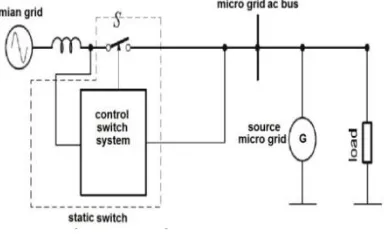
RIDUsing the new control methods along with the DGs, given the security levels, quality, reliability and power availability in distribution networks, generally leads them to move from being dependant to being active and dynamic. The main basis in distribution network results in a new concept called the micro-grid network[8-9]. Micro-micro-grids are LV networks including sources such as micro-turbine, solar cells and power storages like batteries that can be desirable if accompanied by controllable loads and a control system[10]. Figure 1 shows a general scheme of a micro-grid network.
Fig 1.General scheme of a micro-grid
As observed in figure 1, this grid is connected to an MV and it also has the ability to operate in situations separated from the network. From the consumer’s point of view, a micro-grid has the capacity of power generation and heat production. On the other hand, increase in the power quality, reliability, decrease in emissions and voltage drop and also energy with lower price are mentioned later. Micro-grid has a coordinated function between the demand response and productions by DGs, while maximizing the profit for the subscribers and the upstream network.
3 Different Status of a Micro-Grid
A primary pattern of the micro-grid structure and the synchronizer system is illustrated in figure 2. As it is shown, the micro-grid can be as a power producing source and a sample load.
Fig 2. Micro-grid model when connected to a grid A micro-grid is connected to the main grid by the static switch _______________________
Mohammad Jafari Far is with Department of Electrical Engineering, Andimeshk Branch, Islamic Azad
University, Andimeshk, Iran. E-mail:
336 S and the synchronizing system[11]. But it must be considered
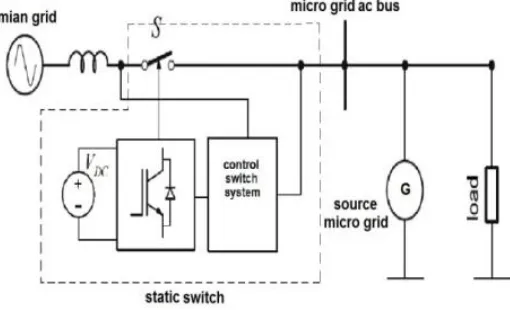
that if the separation of a micro-grid from the main grid is under investigation, the system pattern is as in figure 3. Along with the static switch, there must be an external voltage source and the extra voltage inverter source to make up for the shortage of micro-grid power and prevent the variation in the micro-grid.
Fig 3. Micro-grid model in separation from the grid
A micro-grid has three different functions including: connection to the network, island and transient mode[12]. The transient mode contains current and voltage fluctuations in connection and disconnection of the micro-grid from the main grid to reach the persistent mode.
3.1 State Connection to the Grid
Under these circumstances, in addition to the power production sources in the micro-grid, the main grid also supplies the existing loads in the micro-grid which are more that its production at that time in a way that the power balance between the loads and the power production sources is maintained[13]. In connection to the network, the main goal is the static switch S of chasing voltage in the grid that in case of voltage disorder, disconnects the micro-grid from the main grid. In this article, the disconnection of micro-grids is not investigated and only the micro-grid synchronization with the main grid is under discussion.
3.2 State of Islanding
When there is error in the network or the power direction from the micro-grid to the main grid is changed, the static switch S, disconnects the micro-grid from the main grid and in this condition the main grid must make up for the power voltage source shortage in the micro-grid by an external voltage source and an inverter to help the micro-grid function in a stable way in the island mode without the necessity to deactivate the loads if the micro-grid cannot provide the intended power for the loads using the external source[13-14]. Based on the load management plan determined already according to the load sensitivity, deactivation is applied in some loads. To generate power in the micro-grid, the renewable energy sources are used. These sources are
connected to the micro-grid by the power electronic converters. In islanding mode, the converter of every source controls the voltage and frequency that gains from the grid based on the frequency and voltage feedback in the sense that the source converters have no communication to perform the control process. This independent control is achieved by the high order control loop power or the drop definition method. In fact, voltage control and frequency are the active and reactive power controls.
3.3 State of Transient
When there is disorder in the voltage of the network, the static switch S is open and the micro-grid is disconnected from the grid. In this case, a transient mode happens to the micro-grid. Also when the micro-grid is about to connect to the main grid, the transient mode happens to the micro-grid. Therefore, there are some solutions for the connection and disconnection mode to have the least transient mode for the micro-grid. In this article, the transient mode and the method for reducing the transient fluctuations in connection of the micro-grid to the main grid is investigated. If the micro-grid connection to the main grid is not achieved under certain conditions, a transient mode may occur and cause a variation in the micro-grid [14-15].
4
T
HES
YNCHRONIZATIONS
YSTEMOne of the most important measures before connection to any sources of the grid is the proper and adequate synchronization of the source voltage to the grid voltage. If the source voltage is not synchronized with the grid voltage while connecting to the grid, it causes extra current with high domains. Most of the grid connection systems use a phase lock loop which is peculiar for identifying the voltage phase angle Ɵ in the grid. The synchronizers used for the three-phase systems are based on the implementation of SFR-PLL. The main structure of an SFR-PLL is illustrated in figure 4.
According to the relation, the three-phase lock loop input is first transmitted to the synchronization reference or qd0:
where TƟ is defined as:
Fig 4. Block diagram of SFR-PLL abc
qd
T
x
x
0
*
(1)
1 1 1 ) 3 2 sin( ) 3 2 sin( sin ) 3 2 cos( ) 3 2 cos( cos 3
2
337 IJSTR©2015
Where ,
Tc b a
abc x x x
x is input vector
Td q
qd x x x
x 0 0 is output vector
Therefore, in the above relations, the vector X is replaced by the vector V, the input voltage. The Vq voltage component moves toward zero by a PI controller. The output of PI controller estimates the value of the angular frequency (ω) in the reference synchronization lock loop device.
Based on 3, by the integration of angular frequency, the increased phase angle of reference synchronization device (Ɵ) is obtained. When the component Vq is equal to zero, Ɵ is in agreement with the input voltage angle vector.
5
R
ESULTSS
IMULATIONMicro-grid has several power generation sources and loads. The main objective is the investigation of general behavior of the micro-grid in synchronization with the main grid. Therefore, the micro-grid can be modeled by a power generation source and load model as seen in figure 2. The operation mechanism of most micro-grids are adjusted in a process that the one-way power direction is from the grid to the micro-grid and as this direction is reversed, the micro-grid is disconnected from the main grid. To synchronize a generator with the grid, where the generator must function in the engine mode (gaining power from the grid), its frequency must be a part of the lower grid. The frequency of the micro-grid while synchronizing with the main grid, is considered as a part of the lower main grid. The one linear pattern in figure 5 is simulated as a three phase process in MATLAB. The static switch S in this figure has the responsibility to synchronize the micro-grid with the main grid.
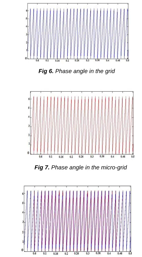
Before synchronizing the micro-grid with the main grid, first the phase lock loops identify the phase angles in the main grid and the micro-grid. In figure 2, the phase lock loop output 1 identifying the voltage phase angles and the phase lock loop output 2 which identifies the voltage phase angles in the micro-grid are illustrated before its connection to the main grid.
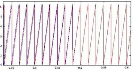
Figure 6 shows the micro-grid phase angle, figure 7 shows the main grid phase angle and figure 8 shows the micro-grid and the main grid phase angle together, where if we consider the main grid phase angle as constant, the micro-grid phase angle moves toward the main grid angle gradually and they lie on each other and then pass through it. When the micro-grid phase angle is exactly on the main grid phase angle, the micro-grid is synchronized with the main grid and it’s the best moment for the micro-grid to connect to the main grid and this case the least transient mode and the least disorder will be in the current and voltage and in other times when the micro-grid phase angle is different from the main grid phase angle, if the micro-grid is connected to the main grid, considering this difference, the disorder in current and voltage maximizes. In simulation, first the static switch connects the micro-grid to the main grid when the micro-grid voltage is not synchronized with the main grid voltage. Results of this incorrect connection which is strong disorder in the current and voltage is shown in
) 0 ( ) ( )
(
t
tdt(3)
Fig 5. The static switch for connecting the micro-grid to the main grid
Fig 6. Phase angle in the grid
Fig 7. Phase angle in the micro-grid
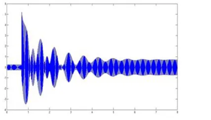
338 figure 9, 10, 11. As it is observed, the time for the occurrence
of the disorder for these parameters to be resolved for the voltage is about 1/8 seconds and for the current is about 6/5 seconds. Also in the voltage domain disorder, the main domain is decreased to 0/75 and the current domain is increased to 5/2. Also in figure 12 and 13, fluctuation in the phase angle is illustrated.
The total cost of power plant unit consists of fuel cost,
Now, if the static switch connects the micro-grid to the main grid when the micro-grid voltage is synchronized with the main grid voltage, the time of the transient mode and the transient modes of the grid parameters are decreased strongly. As it is shown in figure 14, 15, 16, 17 and 18, with this correct connection, the time for the disorder to be resolved is 0/4 seconds for the voltage and 5/5 seconds for the current. Also in the time of domain disorder, the voltage is constant and the current domain takes up the main current domain to 1/8.
Fig 9. Current characteristic in non-phase connection
Fig 10. Voltage characteristic in non-phase connection
Fig 11. Voltage characteristic in the moment of non-phase connection
Fig 12. Phase angle characteristic in the moment of non-phase after connection
Fig 13. Phase angle characteristic in the moment of non-phase connection
339 IJSTR©2015
Regarding the simulation results, if the micro-grid connection to the main grid occurs when the micro-grid voltage is synchronized with the main grid voltage, the disorder time when synchronized with the main grid is less than the main grid frequency. The static switch S in the figure has the responsibility to synchronize the micro-grid with the main grid.
6
C
ONCLUSIONThe micro-grid must connect to the main grid when the micro grid voltage has the same phase as the main grid. The micro grid phase voltage and the main grid are identified by the phase lock loops. In simulation, the micro-grid in both phases with the main grid, is connected to the main grid, as seen in the results when the micro grid and the main grid have the same phase, the connection occurs. The voltage and current disorder is the least and if the connection occurs when the micro grid voltage has not the same phase as the main grid, the voltage disorder is increased after connection regarding the phase difference in voltage. Also when the phase difference is high, the micro grid may become unstable and the current may increase.
R
EFERENCES[1] M. T. Bina and M. D. Eskandari, ―Consequence of
Unbalance Supplying Condition on a Distribution Static Compensator‖, IEEE PESC’04, vol. 5, pp. 3900-3904, June 2010.
[2] R. El-Khazali, N. Tawalbeh, O. Al-Khatib, I. AbuShawish, ― Performance analysis of fractional-order digital phase-locked loops,‖ International Conference on Fractional Differentiation and Its Applications (ICFDA), pp. 23-25, June 2014.
[3] S. Sancho, M. Ponton, A. Suarez, F. Ramirez, ― Analysis of Injection Pulling in Phase-Locked Loops With a New Modeling Technique ,‖ IEEE Transactions on Microwave Theory and Techniques,, vol. 61, no. 3, pp. 1200-1214, June 2013.
[4] N. Pogaku, M. Prodanovic, and T. C. Green, ―Modeling, Analysis and Testing of Autonomous Operation o an Inverter-Based Microgrid‖, IEEE Transactions on Power Electronics, vol. 22, pp. 613-625, 2007.
[5] K. De Brabandere, K. Vanthournout, J. Driesen, G.
Deconinck, and R. Belmans, ―Control of Microgrids‖, in Proc. IEEE Power Engineering Society General Meeting, 2007.
[6] H. Laaksonen, ―Protection Principles for Future
Microgrids‖, IEEE Transactions on Power Electronics, vol.2, pp. 1-10, 2013.
[7] F. Katiraei and M. R. Iravani, ―Power Management
Strategies for a Microgrid with Multiple Distributed Generation Units,‖ IEEE Transactions on Power Systems, Vol. 21, No. 4, pp. 1821-1831, Nov. 2006.
[8] F. Katiraei, M. R. Iravani, and P. W. Lehn, ―Micro-grid
Fig 15. Voltage characteristic of in-phase after connection
Fig 16. Voltage characteristic in the moment of in-phase connection
Fig 17. Phase angle characteristic of in-phase after connection
340 Autonomous Operation During and Subsequent to
Islanding Process,‖ IEEE Transactions on Power Delivery, Vol. 20, No. 1, pp. 248-257, Jan. 2005.
[9] P. Piagi and R. H. Lasseter, ―Autonomous control of microgrids,‖ IEEE Power Engineering Society General Meeting, 2006, 8 pages, 18-22 June 2006.
[10]C. K. Sao, and P. W. Lehn, ―Intentional Islanded Operation of Converter Fed Microgrids,‖ IEEE Power Engineering Society General Meeting, 2006, 6 pages, 18-22 June 2006.
[11]E. J. Davison, N. S. Rau, and F. V. Palmay, ―The optimal
decentralized control of a power system consisting of a number of interconnected synchronous machines,‖ Int. J. Contr., Vol. 18, No. 6, pp. 1313-1328, 2004.
[12]R. E. Brown and L. A. A. Freeman, ―Analyzing the reliability impact of distributed generation,‖ Proceedings of IEEE Power Eng. Soc. Summer Meeting, 2001, Vol. 2, pp. 1013–1018, 15-19 July 2005.
[13]F. De Mango, M. Liserre, A. D. Aquila, and A. Pigazo, "Overview of Anti-Islanding Algorithms for PV Systems. Part I: Passive Methods,‖ in Proc. 12th International Power Electronics and Motion Control Conference, 2006.
[14]K. Ro and S. Rahman, ―Two-Loop Controller for
Maximizing Performance of a Grid- Connected
Photovoltaic-Fuel Cell Hybrid Power Plant,‖ IEEE Transactions on Energy Convers., Vol. 13, No. 3, pp. 276 281, Sep. 2008.
[15]M. C. Chandorkar, D. M. Divan, and R. Adapa, ―Control of