RANDOM PWM ALGORITHMS FOR
VSI FED INDUCTION MOTOR DRIVES
WITH FIXED SWITCHING
FREQUENCY
K. SATYANARAYANA
Pragati Engineering College, Surampalem, E.G Dist Andhra Pradesh, India
J. AMARNATH
E.E.E Department, Jawaharlal Nehru Technological University Kukatpally, Hyderabad, Andhra Pradesh, India
A. KAILASA RAO
Pragati Engineering College, Surampalem, E.G Dist Andhra Pradesh, India
Abstract:
This paper presents two random PWM algorithms for voltage source inverter fed induction motor drives with fixed switching frequency for reduced harmonic distortion and acoustical noise. Moreover, the proposed algorithms use the concept of imaginary switching times, which reduces the complexity involved in the classical space vector approach. The first algorithm is developed by randomizing the time durations of zero voltage vector times and second algorithm is developed by using the variable delay technique. To validate the effectiveness of the proposed algorithm, numerical simulation studies have been carried out on v/f controlled induction motor drives at different modulation indices and results are presented and compared.
Keywords: Induction motor drive, Random PWM, Space vector PWM.
1. Introduction
The voltage source inverters (VSI) fed variable speed AC drives have gained more importance in many industrial applications. To get variable voltage, variable frequency supplies from a VSI, the PWM algorithms are becoming more popular due to their advantages. Among the various PWM algorithms, triangular comparison (TC) approach and space vector (SV) approach are two popular approaches. However, the SV approach is gaining more importance in many applications due to its numerous advantages over TC approach. A detailed survey of various PWM algorithms is given in [1]. In recent years, the space vector PWM (SVPWM) algorithm is attracting many researchers. In the SVPWM algorithm, the reference is provided as a voltage space vector, which is sampled once in every subcycle and an average voltage vector equal to the sampled reference voltage vector is generated by time-averaging of the different voltage vectors produced by the inverter. The SVPWM is a superior PWM technique for three phase inverter drives compared to the traditional regularly sampled triangular comparison technique. Space vector approach has the advantages of lower current harmonics and a possible higher modulation index compared with the three phase sinusoidal modulation method and ease of digital implementation [2].
algorithms use the classical space vector approach, which requires angle and sector information to construct the reference voltage vector in every sampling time period. To reduce the complexity involved in the conventional approach, a novel voltage modulation algorithm is presented in [6] by using the concept of offset time. Moreover, to reduce the complexity involved in the conventional space vector approach, the concept of imaginary switching times is presented in [7]-[8].
This paper presents two popular RPWM algorithms for VSI fed induction motor drives. The proposed algorithm generates the pulses from the sampled reference phase voltages only and thus reduces the complexity involved in the conventional space vector approach.
2. Space Vector PWM Algorithm
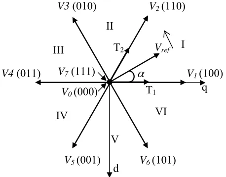
Voltage source inverters (VSI) are utilized in many applications. The three-phase, two-level VSI has a simple structure and generates a low-frequency output voltage with controllable amplitude and frequency by programming high-frequency gating pulses. For a 3-phase, two-level VSI, there are eight possible voltage vectors, which can be represented as shown in Fig. 1. Among these voltage vectors, V1 to V6 vectors are known
as active voltage vectors or active states and the remaining two vectors are known as zero states or zero voltage vectors.
Fig. 1 Possible voltage space vectors for VSI
The active voltage vectors can be represented as given in (1). 6 ..., 1,2, k re whe 3
2 ( 1)3
dc jk
k V e
V (1)
where Vdcis dc link voltage.
The reference voltage space vector or sample, which is as shown in Fig.1 represents the corresponding to the desired value of the fundamental components for the output phase voltages. In the space vector approach this can be constructed in an average sense. Vref is sampled at equal intervals of time,Ts referred to as sampling
time period. Different voltage vectors that can be produced by the inverter are applied over different time durations with in a sampling time period such that the average vector produced over the sampling time period is equal to the sampled value of the Vref, both in terms of magnitude and angle. It has been established that the vectors to be used to generate any sample are the zero voltage vectors and the two active voltage vectors forming the boundary of the sector in which the sample lies. As all six sectors are symmetrical, the discussion is limited to the first sector only. For the required reference voltage vector, the active and zero voltage vectors times can be calculated as in (1), (2) and (3).
s o
i T
M
T123 sin(60 ) (1)
) sin( 3 2
2 Mi Ts
T
(2)
V
refV
1(100)
V
2(110)
V3
(010)
V4
(011)
V
5(001)
V
6(101)
V
0(000)
V
7(111)
2 1 T
T T
Tz s (3)
where Mi is the modulation index and defined as in [1]. In the SVPWM algorithm, the total zero voltage vector
time is equally divided between V0 and V7 and distributed symmetrically at the start and end of the each
sampling time period. Thus, SVPWM uses 0127-7210 in sector-I, 0327-7230 in sector-II and so on.
3. Proposed Random PWM Algorithms
3.1.Concept of Imaginary Switching Times
The standard SV approach uses reference frame transformation and angle calculation. Hence, it increases the complexity involved in the algorithm. But, the proposed approach uses the instantaneous sampled reference phase voltages for the generation of gating times. For the explanation purpose, the concept of imaginary switching times will be introduced. The imaginary switching times are proportional to the instantaneous phase voltages and can be defined as follows:
cn dc s cn bn dc s bn an dc s an V V T T V V T T V V T
T ; ; (4)
an
V , Vbn and Vcn are the instantaneous reference phase voltages and Tan, Tbn and Tcnare the corresponding
imaginary switching times. As these times are proportional to the instantaneous voltages, these times could be negative where the voltages are negative. Hence, these times are defined as imaginary switching times. The active vector switching times T1 and T2, if the reference voltage vector falls in sector-1 may be expressed as
follows [7]-[8]:
cn bn bn
an T T T T
T
T1 ; 2 (5)
In the conventional SVPWM algorithm, when the reference voltage vector falls in the first sector, the imaginary switching time which is proportional to the a-phase (Tan) has a maximum value, the imaginary switching time which is proportional to the c-phase (Tcn) has a minimum value and the imaginary switching time which is proportional to the b-phase (Tbn) is neither minimum nor maximum value. Thus, in general to calculate the active vector switching times, the maximum (Tmax), middle (Tmid) and minimum (Tmin) values of imaginary
switching times are calculated in every sampling time. Then the active vector switching times T1 and T2 may be
expressed as
min 2
max
1 T T ;T T T
T mid mid (6)
The zero voltage vectors switching time is calculated as 2
1 T
T T
Tz s (7)
3.2.Proposed Random Zero Vector Distribution Algorithm
The classical SVPWM algorithm distributes the total zero state time equally among the two possible zero voltage vectors. But, the proposed random zero vector distribution PWM (RZVDPWM) algorithm distributes the zero state time between the two zero voltage vectors as given in (8) and (9).
z
T
T0 (8)
z
T
T7(1) (9)
where is a random number, which varies from 0% to 100% and must be less than one. The sequence and timing of application of zero states and active states in the first sector are shown in Fig.2 for both SVPWM and proposed RZVDPWM algorithm.
As shown in Fig. 2, the proposed RZVDPWM algorithm randomizes the zero voltage vector times in every sampling time interval but, all the pulses must be centre aligned as in standard SVPWM algorithm.
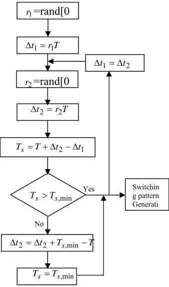
3.3.Proposed Variable Delay Randomization PWM Algorithm
(a) (b)
Fig. 2 Sequence and gating times in sector –I (a) SVPWM algorithm (b) proposed RZVDPWM algorithm
Fig. 3 Flowchart of the proposed VDRPWM algorithm
4. Simulation Results and Discussions
To validate the proposed algorithms, the numerical simulation studies have been carried out using MATLAB. For the simulation studies, the average switching frequency of the inverter is taken as 5 kHz. The induction
1
r
=rand[0
T r t1 1
2
r
=rand[0
T r t2 2
min , s s T T 1 2 t t T
Ts
s
s T
T t
t
2 2 ,min
min , s s T T Switchin g pattern Generati Yes No 2 1 t
t
Ts
Ts
2
zT
2
zT
2
zT
1T
T
2T
2T
12
z
T
Ts
Ts
1
T
T
2T
2T
1z
T
)
1
(
zT
motor used in this case study is a 4 kW, 400V, 1470 rpm, 4-pole, 50 Hz, 3-phase induction motor having the following parameters: Rs= 1.57Ω, Rr = 1.21Ω, Ls = 0.17H, Lr = 0.17H, Lm = 0.165 H and J = 0.089 Kg.m2.
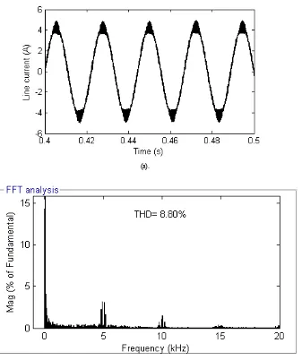
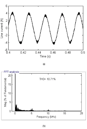
The steady state line current waveforms and harmonic spectra of line current along with their total harmonic distortion (THD) value for SVPWM, RZVDPWM and VDRPWM algorithms are shown in from Fig. 4 to Fig.6 at different modulation indices. From the simulation results, it can be observed that the proposed random PWM algorithms give less harmonic distortion and hence less acoustical noise when compared with the standard SVPWM algorithm.
(a)
(b)
(a).
(b)
5. Conclusions
In this paper, novel and simplified random PWM algorithms by using the concept of imaginary switching times are presented for induction motor drives. This paper presented two different types of random PWM algorithms. As the proposed approach eliminates the angle calculation, it is characterized by low computational overhead and easy to implementation. The demonstrated mitigation of the harmonic distortion and acoustical noise are the important advantages of the proposed random PWM algorithms.
(a)
(b)
References
[1] Joachim Holtz, “Pulsewidth modulation – A survey” IEEE Trans. Ind. Electron.., vol. 39, no. 5, Dec 1992, pp. 410-420.
[2] Heinz Willi Vander Broeck, Hnas-Christoph Skudelny and Georg Viktor Stanke, “Analysis and realization of a pulsewidth modulator based on voltage space vectors” IEEE Trans. Ind. Applicat., vol. 24, no. 1, Jan/Feb 1988, pp. 142-150.
[3] Michael M.Bech, Frede Blaabjerg, and John K. Pedersen, “Random modulation techniques with fixed switching frequency for three-phase power converters” IEEE Trans. Power Electron., vol.15, no.4, pp. 753-761, Jul, 2000.
[4] S-H Na, Y-G Jung, Y-C. Lim, and S-H. Yang, “Reduction of audible switching noise in induction motor drives using random position space vector PWM” IEE. Proc. Electr. Power Appl., vol.149, no.3, pp. 195-200, May, 2002.
[5] Andzrej M. trzynadlowski, Konstantin, Yuin Li, and Ling Qin, “A novel random PWM technique with low computational overhead and constant sampling frequency for high-volume, low-cost applications” IEEE Trans. Power Electron., vol. 20, no.1, pp.116-122, Jan, 2005.
[6] Dae-Woong Chung, Joohn-Sheok Kim and Seung-Ki Sul, “Unified voltage modulation technique for real-time three-phase power conversion” IEEE Trans. Ind. Applicat., vol. 34, no. 2, Mar/Apr 1998, pp. 374-380.
[7] T. Brahmananda Reddy, J. Amarnath and D. Subbarayudu, “Improvement of DTC performance by using hybrid space vector Pulsewidth modulation algorithm” International Review of Electrical Engineering, Vol.4, no.2, pp. 593-600, Jul-Aug, 2007. [8] K. Satyanarayana1, J. Amarnath2, and A. Kailasa Rao1, “Hybrid PWM Algorithm with Low Computational Overhead for Induction