Please cite this article as: M. Rezaiee-Pajand, M. Momenipour, S. M. Hozhabrossadati, Three Different Methods for Approximate Analysis of Bar Structures, International Journal of Engineering (IJE), IJE TRANSACTIONS A: Basics Vol. 33, No. 1, (January 2020) 47-54
International Journal of Engineering
J o u r n a l H o m e p a g e : w w w . i j e . i rThree Different Methods for Approximate Analysis of Bar Structures
M. Rezaiee-Pajand*a, M. Momenipoura,b, S. M. Hozhabrossadatib
a Department of Civil Engineering, Ferdowsi University of Mashhad, Iran
b Department of Civil Engineering, Toos Institute of Higher Education, Mashhad, Iran
P A P E R I N F O
Paper history: Received 03 June 2019
Received in revised form 03 November 2019 Accepted 08 November 2019
Keywords: Approximate Analysis Bar Structure Rational Approximation Unimodal Component Displacement Error Computational Effort
A B S T R A C T
In this paper, modified solutions were compared through utilizing three different approximate methods for bar structures. The modifications considered various changes in the initial design. To authors' best of knowledge, the studies have carried out on this matter so far are not broad enough and have considerred the simeltaneous variations of size, geometry and topology on the bar structures. In this study, three well-known methods, including combined approximation, rational approximation and the approximate inversion of stiffness matrix methods are formulated. A large variety of problems will be performed with different characteristics to compare the ability of these approaches in determining the suitable approximate modified displacements. Cross sectional properties and nodal coordinates are considered as design variables. Displacement errors and computational efforts of the processes considered as comparison factors. It is shown that the approximate inversion of the stiffness matrix method cannot solve the problems, which requires the modification of structural geometry. Furthermore, the combined approximation and rational approximation methods have the ability of reaching displacements with suitable quality in the problems with a moderate size.
doi: 10.5829/ije.2020.33.01a.06
1. INTRODUCTION1
Many structural problems can be solved by running repeated procedures. In other words, structural response can be achieved gradually. Every step of the problem solving procedure includes extensive computations. Structural analysis contributes the largest part in the computational effort. This obstacle has led to numerous studies on approximate reanalysis methods. The purpose of utilizing these approaches is to achieve the structural response after each change in design without solving the modified equations. This will highly decrease the computational costs. The different approximate reanalysis methods may determine exact or approximate responses for the modified structure. It should be mentioned that in these analyses, the exact relations, which are usually complicated, are substituted by approximate methods. Structural optimization, designing damage-proof structures, structural nonlinear analysis, and eigenvalue problems are among the current problems the solutions of which needs reanalysis [1].
*Corresponding Author Email: [email protected] (M. Rezaiee-Pajand)
vector-valued sequences. Sidi suggested procedures to achieve rational approximations in partial sum of Macluren series of a vector-valued complex function. He named this approach the process of rational approximation [5]. Wu et al. [4] then dealt with the extension of the range of validity of the truncated power series by using this method and represented approximate solutions. Inverse of the stiffness matrix was represented in the form of an explicit function of cross sectional properties and material constants of structural elements. Impollonia [6] achieved this function by the non-conventional assembly of global stiffness matrix and using Sherman-Morrison-Woodbury (SMW) relation. He factorized the element stiffness matrix following the unimodal component's concept. The idea of unimodal components was raised by Fuchs [7, 8] for the first time. He emphasized that the explicit and exact responses of all the structures are achievable from scientific hypothesis point of view, but as they have a great number of terms, are not practically useful [9]. Utilizing the most effective terms of the exact pattern will form the explicit function of approximate response. Using such a method on the exact inverse function of stiffness matrix, Impollonia represented relations to determine the approximate inverse of this matrix. Wang et al. [10] suggested a modified CA approach to deal with reanalysis problems. Gao et al. [11] presented a reanalysis method for the structures with local modification. The algorithm was based on block matrix. Moreover, Wang et al. [12] integrated reanalysis methods and apace mapping algorithms to tackle optimization problems. Kim and Eun [13] considered structural reanalysis due to addition/removal of substructures and changes in design variables by a generalized inverse method. Based on polynomial-type extrapolation for reanalysis of structures under changes in the initial design, Hosseinzadeh et al. [14] proposed another approach. The force method for the reanalysis of structures was adopted by Koohestani [15]. By utilizing sequential piecewise linear programming to deal with the topology optimization, Senne et al. [16]combined approximate reanalysis technique. While the concurrent variations of size, geometry, and topology of structures are important cases for the analysis and design of structures, to the best of authors' knowledge, no articles have investigated such simultaneous variations in the bar structures. Therefore, this is the main goal of the present article to fill this gap. This article studies three approximate procedures for analyzing the structures, and records its computational efforts. To evaluate the aspects of these methods, a comprehensive computer program is designed by the authors. This program can analyze the bar structures. It is assumed that the materials behave like linear elastic. Furthermore, the members are assumed to be in the small deformation regime. Besides, the members are homogeneous and isotropic. Various examples, which include different forms of the design
modification, are solved. The displacement errors and computational efforts are the criteria to compare these approaches. After performing extensive numerical computations, the characteristics of each method are revealed, according to the results of the analysis. Outcomes demonstrate the CA and RA methods provide better solutions than SMW approach.
2. REANALYSIS
In this section, the basis of problems are reanalysized. Such a problem in structural mechanics consists of following steps:
1. Given an initial design, the stiffness matrix Sand load vector P , the initial displacements 𝐝∗ are computed
through equilibrium equations [1]: =
S d P (1)
2. Assuming a change in the design variables, the corresponding changes in the stiffness matrix and load vector are as follows:
(
, ,)
ΔS=ΔS c g m (2)
(
, , ,)
ΔP=ΔPc e g m (3)
The parameters of c, e. g. and m represent the properties of the structure and its environment. Cross sectional properties are represented by c, geometry of the structure by g, and the mechanical properties of the material by m. the parameter e is the external load acting on the structure.
3. The modified stiffness matrix S and load vector P are given as follows:
Δ
= +
S S S (4)
Δ
= +
P P P (5)
4. The reanalysis approaches should be able to compute modified displacements d without solving the complete set of modified analysis equations.
(
+Δ) (
= +Δ)
S S d P P (6)
3. COMBINED APPROXIMATION METHOD
As pointed out in the Introduction, Kirsch [2] developed this scheme in 1980s. The following is an introduction of each part contained in this method:
number of linearly independent basis vectors [17]:
1 1 2 2 s s B
y y y
= + + + =
d d d d d y (7)
Basis vector matrix dB contains vectors of given values. The number of these vectors s is defined as less than the number of degrees of freedom n. Substituting equation (7) into the modified analysis equation (6), utilizing the reduced stiffness matrix SR and load vector PR introduced in Equations (8) and (9), the set of equation (10) is achieved to determine the coefficient vector y:
T R = B B
S d S d (8)
T R = B
P d P (9)
R = R
S y P (10)
3. 2. Binomial Series Choosing a proper set
of basis vectors in the reduced basis method is of great importance. Rearranging Equation (6), binomial series of the modified displacement function can be expressed as follows [4]:
(
2)
1 11 2 3 ; Δ
− −
= − + − = + + + =
d I B B S P d d d B S S (11)
Being the spectral radius or the greatest eigenvalue of matrix B less than 1, makes the binomial series converge. The basis vectors are calculated by the following recurrence relation:
( )
1 11 1 1; 2,3, ,
i i
i i i s
− − −
= − = − =
d Bd B d (12)
4. RATIONAL APPROXIMATION METHOD
Wu et al. [4] proposed this method after the CA in 2003. The following is the way how some approximations are made for the solution of the reanalysis problem:
4. 1. POWER SERIES If the artificial parameter ε is
utilized in the interval of [0 1], the set of equations governing the modified structural behavior stated as follows [4]:
(
+ε Δ)
=S S d P (13)
The power series of response function is given as follows:
2
1 2 3
( )
pse ε = + ε+ ε +
d d d d (14)
The coefficient vectors are computed by the following recursive relation:
1 1
1
1 1
1
; 2,3, ,
,
i
i i i s
Δ − − − − = = = = − =
d Bd B d
B S S d S P (15)
The partial sum of power series (14) can be expressed as follows:
( )
11
; 1, 2,
o i o i i o − = =
=F d (16)
This series has a finite radius of convergence and its partial sum validity limits to the neighborhood of zero. Thus, the responses which are achieved by putting an amount of one for in Equation (16) are not appropriate.
4. 2. Rational Approximation Procedures According to works of Sidi [5] and Wu et al. [4], one can write:
( ) 1 1 ( ) 1 1 1 1 1 1
, 1; 1, 2,
o o j
j j
j o
ra o o j
j j o o k i o
k k i
i o
o o j
i j
j
c ε ε ε
c ε c ε
with c o c ε − + = − + = − + + = − + = = = = = =
F d d (17)Where cj factors are determined by solving a system of equations of the form:
1 ` 1
; 1 1,
o
T
ij j io ij i j
j
d c d i o d
−
=
= − − =
d d (18)Rewriting the coefficient matrix in Equation (13) as follows:
(
1)
(
)
ε Δ ε ε Δ
+ = − + +
S S S S S (19)
It has been derived that the matrix is positive definite and has no pole point for 0ε1. Therefore, by putting the amount of one for in Equation (17) the approximate response of Equation (13) will be achieved:
( )
1 1
1 1; 1, 2, ,
o o
k
o k i
ra o i o
i j
j
c
ε with c o s
c = = = = = = =
d d (20)
5. THE APPROXIMATE INVERSION OF STIFFNESS MATRIX METHOD
The third method which revolves around the inverse of the stiffness matrix is explained bellow:
5. 1. Decomposition of Element Stiffness Matrix Element stiffness matrix an explicit function of the cross-sectional properties, the material properties and the element geometry can be decomposed into its unimodal components as follows [6]:
( )
( )
( ) ( ) ( )( )
( ) ( ) ( ) ( ) ( ) ( ) ( )( )
( ) ( ) 1 1 T e eα T α
e e e e e e
N N
e e e e e
i i i i i
where the diagonal matrix ( )e
( )
( )e lists the stiffness of all the unimodal components, ( )ei
α , and its order ( )e α N is equal to the number of those components in the finite element. Structural topology properties are included in the matrix ( )e
which has dimension
(
( )e ( )e)
dof αN N with
( )e dof
N being number of degrees of freedom of element. Equation (21) derived for 2D truss elements are given as follows: ( ) ( )
( )
( ) ( ) ( ) ( ) T exx xy xx xy
e e e e
e
1
Φ C C C C
2 2E A Λ α L = − − = (22)
here the cross section area, Young modulus, the length of the element and directive cosines are denoted by ( )e
A , ( )e
E , ( )e
L and C , respectively.
5. 2. Stiffness Matrix Assemblage When the
element stiffness matrix is factorized in the global frame, the global stiffness matrix is amenable to a non-conventional assemblage, which demonstrates the contribution of each unimodal element. The global stiffness matrix can be assembled in the following form [6]:
( )
T = S (23)
The matrix is built up by assembling the matrices ( )e
according to element connectivity.
5. 3. The Approximate Inverse of the Stiffness Matrix The Sherman-Morrison-Woodbury (SMW) formula determines the modification of the inverse of the initial stiffness matrix [18, 19]. Impollonia [6] suggested two approximate patterns imitating the exact explicit solution derived by the SMW formula. In the first pattern, the contributions of unimodal stiffness fluctuation in modification of initial stiffness matrix inversion are linearly superimposed:
1
1 1
0 0
1 11
N N
T i
i i i i
i i i i
λ λ λ a − − − = = = + − +
S S S A (24)
where the following quantities appear:
1 1 1
0 , 0 0
T T
i i i i i i
a = S− A =S− S− (25)
Being S0 the reference stiffness matrix where the unimodal stiffness components take their reference values, α0i . Unimodal stiffness fluctuation around its reference value is shown by λi.
The second procedure takes into account the interaction effects among the fluctuations of the unimodal stiffness components.
(
)
(
)
1 1 1 0 0 1 1 2 2 1 1 1 1 1 1 1 N N T ii i i i
i i i i
N
i j ij
i i i j j i j i j ij j i
j T
i
i j ij ij
i i j j ij
λ λ
λ a λ λ a
λ a λ a λ λ a a a
λ λ
λ a λ a a
− − − = = = = + = + − + − + + + − + − + + +
S S S A
A A A A
(26)
where the new numerical quantities read:
1 1 1
0 , 0 0
T T
ij i j ij i j
a = S− A =S− S− (27)
One could set the reference values equal to the initial design values, αi , if the amount of the following parameter is small:
1 1 N i i i λ μ N α =
=
(28)here λi
is the fluctuation around initial design. Another choice for the reference values is to assume
(
)
0i 1 i
α = +μ α . So operating, in Equations (24)-(27):
1
1 0
1 ,
1 μ λi λi μαi
−
− = = −
+
S S (29)
being S the initial stiffness matrix made by the initial unimodal stiffness.
6. NUMERICAL EXAMPLES
Several bar structures are analyzed in this section. To this end, a special-purpose code based on three approximate analysis approaches, and approximate displacements are developed. The robustness of methods in achieving the allowed error of 0.5 and 5 percent is evaluated together.
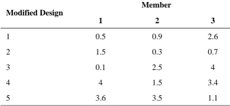
6. 1. The 3-Member Bar Structure Figure 1 is a bar structure the cross-section of the members of which are circles with diameters of 10, 5, and 2.5cm, respectively. The modulus of elasticity is 7 10 5Kgf cm2
. Intensity of the force influencing the second node of the structure is in direction of +X, equal to 20000 Kgf. The
properties of the modified structures are recorded in Tables 1 and 2.
response. The number of problems at the time of size variable modification in which each of the SMW procedures brings about an error more than the exact value, in problem numbers 1, 2, and 4 are respectively 4, 1, 7 and 7 and in problem numbers 3 and 5, are 4, 1, 7, and 6. Using the geometry variables, the methods of CA and RA determine the exact response and the method of CA has a less computational cost in all the problems. In these problems in the 35 cases possible, each of the SMW procedure versions, respectively in 5, 20, 2, and 8 cases achieved better displacements. Moreover, the error of each of 6, 3, 7, and 7 problems is more than the error of the exact amount. If modification occurs at the same time with the variables of size and geometry, the number of analyses will be
(
5549)
. Only in one case the RA method has a less computational cost, and in all the problems, both methods determine the exact response. Each of the SMW versions, respectively in 27, 660, 17, and 521 problems provide better displacements. Three modified structures in topology are achieved through omission of members 1, 3, 2 and 3, from the initial design. In all three problems, the exact displacements are achieved through RA and CA methods. Furthermore, CA method in all cases includes less computational efforts. If the SMW method is used, in the first two cases, the exact responses are achieved through the first version and without the help of the interaction effects, and in the third problem, where the numbers of degrees of freedom decrease, the first version that does not consider the interactions brings about the smallest error.6. 2. The 9-Member Bar Structure The structure members in Figure 2 include the modulus of elasticity of
6 2
2 10 Kgf cm . The forces with the intensity of 40000,
30000, 15000, and 25000 Kgf affect the nodes of 3, 5, 7, and
9, respectively in the direction of +X. The initial and modified cross sections, and the modified geometry of the structure are chosen respectively from Tables 3 and 4.
Figure 1. 3-Member Bar Structure
TABLE 1. The Ratio of the Size of Modified Cross Sections to the Initial in the 3-Member Bar Structure
Member Modified Design
3 2
1
2.6 0.9
0.5 1
0.7 0.3
1.5 2
4 2.5
0.1 3
3.4 1.5
4 4
1.1 3.5
3.6 5
TABLE 2. The Horizontal Modified Coordinates of the 3-Member Bar Structure (Centimeters)
Node Modified Design
4 3
2 1
300 200
150 0
1
355 190
150 0
2
312.5 212.5
100 0
3
365 187.5
45 0
4
585 195
12.5 0
5
Figure 2. 9-Member Bar Structure
TABLE 3. The Size of Initial and Modified Cross Sections of 9-Member Bar Structure (Square Centimeters) Member
Cross Section
9 8
7 6
5 4
3 2
1
36.62 56.25
19.64 44.18
24.54 44.18
19.64 19.64
36.62 Initial
164.87 225
60.13 78.54
18.41 78.54
11.04 11.04
145.21 Modified
TABLE 4. The Horizontal Modified Coordinates of 9-Member Bar Structure (Centimeters) Node
X
10 9
8 7
6 5
4 3
2 1
750 650
575 475
387.5 350
300 200
125 0
Approximate analysis of (29-1) structures that have
undergone modification in the size of cross section, shows that the RA and CA methods include a less computational effort respectively in 491 and 20 problems. Furthermore, in all the problems the exact response is achievable. If the SMW approach is utilized, the exact displacements are achieved in all problems, and its first version will include fewer operation counts. In another case only the horizontal coordinates of structural nodes undergo change. In this case (29-1) problems are
analyzed. It is clear that the methods of RA and CA are superior to each other in 509 and 2 problems, respectively. The exact response is achieved in all problems. The problems, in which the first version of SMW provides a more proper response, are more in the number. If the cross sections are respectively 36.62, 36.62, 19.64, 24.54, 24.54, 24.54, 19.64, 36.62, and 36.62, square centimeters, the topology modification of the initial design will bring about elimination and addition of the members. (24-1) analyses have been
carried out. The RA and CA methods have less computational efforts in 6 and 9 problems, respectively. In both cases, response errors can be placed in the interval of exact displacement errors. If the SMW method is applied, the exact response is achievable and its first version has little computational costs. Now the variables of geometry and size are modified together. In this case, (29-1)(29-1) approximate analysis is performed through
each of the procedures. The rational approximation method in most of the problems has fewer operation counts than combined approximation. In this case, the first version of SMW procedure has less computational cost. In all problems, the exact response is achievable. Approximate reanalysis is performed at the time of simultaneous geometrical and topological modification of (29-1)(24-1) structures. RA has a less computational
cost than CA in most of the problems. In all the problems, the exact response is achievable. Since the exact response is achieved through all the procedures of SMW, the first
version of this method is the best, as it includes a less computational effort.
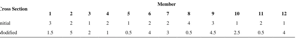
6. 3. The 12-Member Bar Structure The cross-sectional properties, geometry and loading of the bar structure in Figure 3 have arbitrary units. The modulus of elasticity is 30000. The sizes of initial and modified cross sections of the bars are entered in Table 5. The modified geometry of the structure is represented in Table 6. Three concentrated forces with the magnitude of 100, 300, and 200 affect the nodes 3, 4, and 7 in the direction of +X.
If all the problems possible at the time of modification of cross-sectional variables and structural geometries are taken into account, (212-1) and (28-1) problems will be
analyzed, respectively. The exact responses are achieved with 0.5 percent error in all the problems and in both cases by using the processes of RA and CA. In the former case the methods of RA and CA, respectively in 4082 and 13 problems have fewer equation counts. If the process of SMW is utilized, each of its four versions respectively in 16, 2245, 1, and 1833 problems provide more proper displacements. Furthermore, their response errors respectively in 4083, 4017, 4095, and 4085 do not get placed in an exact interval. In the second case, the method of RA needs less computational effort in all cases. SMW process versions do, in this case, provide better responses respectively in 2, 106, 4, and 143 problems. Each of them
Figure 3. 12-Member Bar Structure
TABLE 5. The Size of Initial and Modified Cross-Sections of 12-Member Bar Structure Member
Cross Section
12 11
10 9
8 7 6 5
4 3 2 1
1 2
1 3
4 2 2 1
2 1 2 3
Initial
4 0.5
2.5 4.5
0.5 3
4 0.5 1
2 5 1.5 Modified
TABLE 6. The Horizontal Modified Coordinates of 12-Member Bar Structure Node
X
9 8
7 6
5 4
3 2
1
300 260
210 190
150 100
50 10
respectively in 255, 250, 255, and 254 problems do not reach the accuracy level of 0.5 percent. If the problems that have undergone simultaneous modification in size and geometry are analyzed, there will be less computational effort needed for RA and CA procedures respectively in 997977 and 46248 cases. The error in each process respectively in 21116 and 24353 problems is more than the error of exact value. Also both methods in 11343 common problems do not reach the accuracy level of 0.5 percent. The versions of SMW procedures provide better displacements respectively in 33663, 503115, 51039, and 456408 problems. Their response error does not get placed in the allowed interval of 0.5 percent respectively in 1044223, 1044188, 1044225, and 1044224 problems.
7. CONCLUSION
Three important methods for the reanalysis of structures were investigated in this article. These approaches are called combined approximation (CA), rational approximation (RA) and the approximate inversion of stiffness matrix or Sherman-Morrison-Woodbury (SMW) methods. After formulating all schemes, several examples were solved in order to evaluate the robustness of each methods. Findings show that, in general, the SMW method cannot solve the problems which rise with the modification of structural geometry. On the other hand, outcomes suggest that the RA method reaches the favorable accuracy level in more cases with less computational efforts. It should be added that the relations of the process of CA are based on the structural concepts. That is why, though the ability of the method in solving different problems is high, its understanding is easy.
8. REFERENCES
1. Kirsch, U., "A unified reanalysis approach for structural analysis, design, and optimization", Structural and Multidisciplinary Optimization, Vol. 25, No. 2, (2003), 67-85.
2. Kirsch, U. and Hofman, B., "Approximate behavior models for optimum structural design", (1981), Technion-Israel Inst Of Tech Haifa Dept Of Civil Engineering.
3. Kirsch, U., "Reduced basis approximations of structural displacements for optimaldesign", AIAA Journal, Vol. 29, No. 10, (1991), 1751-1758.
4. Wu, B., Li, Z. and Li, S., "The implementation of a vector-valued rational approximate method in structural reanalysis problems",
Computer Methods in Applied Mechanics and Engineering, Vol. 192, No. 13-14, (2003), 1773-1784.
5. Sidi, A., "Rational approximations from power series of vector-valued meromorphic functions" (1992), Computer Science Department, Technion.
6. Impollonia, N., "A method to derive approximate explicit solutions for structural mechanics problems", International Journal of Solids and Structures, Vol. 43, No. 22-23, (2006), 7082-7098.
7. Fuchs, M.B., "Unimodal beam elements", International Journal of Solids and Structures, Vol. 27, No. 5, (1991), 533-545. 8. Fuchs, M., "Unimodal formulation of the analysis and design
problems for framed structures", Computers & Structures, Vol. 63, No. 4, (1997), 739-747.
9. Fuchs, M.B., "Analytic representation of member forces in linear elastic redundant trusses", International Journal of Solids and Structures, Vol. 29, No. 4, (1992), 519-530.
10. Wang, H., Li, E. and Li, G., "A parallel reanalysis method based on approximate inverse matrix for complex engineering problems", Journal of Mechanical Design, Vol. 135, No. 8, (2013), 081001.
11. Gao, G., Wang, H., Li, E. and Li, G., "An exact block-based reanalysis method for local modifications", Computers & Structures, Vol. 158, (2015), 369-380.
12. Wang, H., Fan, T. and Li, G., "Reanalysis-based space mapping method, an alternative optimization way for expensive simulation-based problems", Structural and Multidisciplinary Optimization, Vol. 55, No. 6, (2017), 2143-2157.
13. Kim, Y.-S. and Eun, H.-C., "Reanalysis of modified structures by adding or removing substructures", Advances in Civil Engineering, Vol. 2018, (2018), Article ID 3084078.
14. Hosseinzadeh, Y., Taghizadieh, N. and Jalili, S., "A new structural reanalysis approach based on the polynomial-type extrapolation methods", Structural and Multidisciplinary Optimization, Vol. 58, No. 3, (2018), 1033-1049.
15. Koohestani, K., "Structural reanalysis via force method",
International Journal of Solids and Structures, Vol. 136, No., (2018), 103-111.
16. Senne, T.A., Gomes, F.A. and Santos, S.A., "On the approximate reanalysis technique in topology optimization", Optimization and Engineering, Vol. 20, No. 1, (2019), 251-275.
17. Kirsch, U., "Combined approximations–a general reanalysis approach for structural optimization", Structural and Multidisciplinary Optimization, Vol. 20, No. 2, (2000), 97-106. 18. Akgün, M.A., Garcelon, J.H. and Haftka, R.T., "Fast exact linear and non‐linear structural reanalysis and the sherman–morrison– woodbury formulas", International Journal for Numerical Methods in Engineering, Vol. 50, No. 7, (2001), 1587-1606. 19. Hager, W.W., "Updating the inverse of a matrix", SIAM Review,
Three Different Methods for Approximate Analysis of Bar Structures
M. Rezaiee-Pajanda, M. Momenipoura,b, S. M. Hozhabrossadatib
a Department of Civil Engineering, Ferdowsi University of Mashhad, Iran
b Department of Civil Engineering, Toos Institute of Higher Education, Mashhad, Iran
P A P E R I N F O
Paper history: Received 03 June 2019
Received in revised form 03 November 2019 Accepted 08 November 2019
Keywords: Approximate Analysis Bar Structure Rational Approximation Unimodal Component Displacement Error Computational Effort
هدیکچ
دوبهب یبیرقت شور هس هسیاقم هب هلاقم نیا یزاس
خساپ س هزا هلیم یاه یم یا ا .دزادرپ راک نی ینوگرگد نوگانوگ یاه ی
رد ار
نیتسخن حرط دنک یم دراو
شهوژپ . یاه ناینیشیپ و هسدنه ،هرادنا نامزمهرثا هرکیپ
ار هزاس رد هلیم یاه یا .دنا هدرکن یسررب
،هلاقم نیا رد هس
هار یبیکرت بیرقت راک ،
هطبار یتخس سیرتام یبیرقت یزاس نوراو و یقطنم بیرقت یم یزاس
هلأسم .دنوش یاه
یدایز دهاوخ لح یم راکشآ یبیرقت هتفایدوبهب ناکمرییغت نتفای رد هویش ره یرترب و دش
یگژیو .ددرگ و عطقم حطس یاه
هصتخم تشادنپ یحارط یاهریغتم یهرگ یاه ی
یم اب .دنش شلات و ناکمرییغت یاهاطخ یاه
یواکاو ب اهدنیارف یار لماع یاه
شور هسیاقم ب اه
ه یم راک یم ناشن اه هجیتن .دنور دنهد
، هلأسم دناوت یمن یتخس سیرتام یبیرقت یزاس نوراو شور اب یاه
هویش ،نیا رب نوزفا .دننک لح ار هسدنه ینوگرگد خساپ نتفای ییاناوت یقطنم و یبیکرت بیرقت یاه
طسوتم هزادنا اب بسانم
.دنراد ار doi: 10.5829/ije.2020.33.01a.06