Please cite this article as: M. Taghilou, B. Ghadimi, M. H. Seyyedvalilu, Optimization of Double Pipe Fin-pin Heat Exchanger Using Entropy Generation Minimization, International Journal of Engineering (IJE), TRANSACTIONS C: AspectsVol. 27, No. 9, (September 2014) 1431-1438
International Journal of Engineering
J o u r n a l H o m e p a g e : w w w . i j e . i rOptimization of Double Pipe Fin-pin Heat Exchanger using Entropy Generation
Minimization
M. Taghilou* a, B. Ghadimib,M. H. Seyyedvalilua
aFaculty of Mechanical Engineering, University of Tabriz, Tabriz, Iran
bSchool of Mechanical Engineering, College of Engineering University of Tehran, Tehran, Iran
P A P E R I N F O
Paper history: Received 11 August 2013
Received in revised form 11 December 2013 Accepted in 22 May 2014
Keywords:
Double Pipe Heat Exchanger Fin-pin
Entropy Generation Optimization
A B S T R A C T
The main aim of this work is devoted to numerical optimization of fin-pin arrangement in the double pipe heat exchanger. For this reason, heat exchanger which is used by Sahiti et al. was studied as an initial geometry. Since they did not consider the fin-pin arrangement effects, modification of their model by changing the fin arranges and using the Brent’s optimization algorithm based on the thermodynamically design concept, would be useful. In this work, by minimizing the entropy generation in constant heat duty per length and constant fins diameters D and changing the pin’s longitudinal (SL) and transversal (ST)
distances, better results have been achieved. Results showed that, in all conditions entropy generation number decreased and consequently leads to reduction in pumping power and manufacturing costs.
doi:10.5829/idosi.ije.2014.27.09c.13
1. INTRODUCTION1
With the arrival of higher priced energy in the 1970’s, in addition to restriction of energy resources and environmental issues, the push started towards thermal efficiency. A push which is now motivated by the need to reduce operating and manufacturing costs. Based on the broad applications, optimal design of heat exchangers has vital importance and directs the engineers towards more efficient heat exchangers designs. Hence, each method which can bring us closer to reach this purpose would be of great interests. Deylami et al. [1] studied the influence of variation in rib-height to channel-height ratio (e/H) on the heat transfer and pressure drop characteristics inside a channel with corrugated upper and lower plates.
Thermodynamic design is a well-established
optimization method which has been used by some scholars. Bruno et al. [2] determined the optimal characteristics of peripheral finned-tube heat exchanger through a combination of semi-empirical values of heat
*Corresponding Author Email: [email protected] (M. Taghilou)
analysis on the heat transfer and flow of a horizontal
concentric tube heat exchanger are studied by Naphon [5]. Naphon investigated the effect of relevant parameters on the entropy generation, entropy generation number, and energy loss and validated the predicted results obtained from the model with the experimental data. Narayan et al.[6] minimized entropy generation in the simultaneous heat and mass exchange devices. Guo et al. [7] have shown that in the shell and tube heat exchanger, entropy generation minimization for the given heat duty, yields increase in effectiveness and decrease in pumping power, but for given flow area, despite the increase in pump power, increasing the thermal efficiency of heat exchanger would have a more effective role in design. Ogulata and Doba [8] minimized entropy generation number in cross flow heat exchanger by definition of three parameters, called optimum flow path length, dimensionless mass velocity and dimensionless heat transfer area. Hadidi et al. [9] proved that traditional design methods such as genetic algorithm, besides being time consuming do not guarantee the reach of an economically optimal solution. Hence, they reach to the optimal design of shell and tube heat exchanger by using ICA2 method. Similar work has been done in this regard by Yousefi et al. [10]. They utilized seven geometrical parameters to optimize flat plate heat exchanger and finally showed that ICA can find better results than traditional Genetic Algorithms (GA). Giangaspero and Sciubba [11] optimized the configuration of the heat exchange surfaces in a Solar Rooftile, by the use of the entropy generation minimization method. They reported that the geometry with pin-fins has the best performance among the tested ones. In addition, the optimal pin array shape parameters (pitch and span) can be determined by a critical analysis of the integrated and local entropy maps and of the temperature contours. Ghassabi and Kahrom [12] have improved heat transfer efficiency of a domestic gas burner by enhancing heat transfer from flue gases. They optimized the insert geometry by the multi-objective genetic algorithm. Amanifard et al. [13] have predicted the optimal design points of forced convective heat transfer in tubular arrangements by using a multi-objective optimization technique. They tried to calculate the most favorable geometric characters which may gain to a maximum heat exchange as well as a minimum pressure loss. Among all these researches, optimization of fin-pin heat exchanger has been just investigated by Sahiti et al. [14]. They developed an optimization model on the basis of the entropy generation minimization, for different flow lengths of pin fin heat exchanger and different pin length. In their work, the influence of the blade arrangement inside a heat exchange was not mentioned.
21
Imperialist Competitive Algorithm
In this paper, optimization of a double pipe pin-fin heat exchanger (Figure1a) is investigated by entropy generation minimization method, based on the blades arrangement. Effective parameters in the performance of heat exchangers are mainly classified into two cases. First are the geometrical parameters and second are the operating conditions (Reynolds number and operating temperature). In the current work, by changing the pin’s longitudinal (SL) and transversal (ST) distances (Figure 1b), at the fixed heat duty and pin diameter (D), minimization of entropy generation leads to better results with respect to Sahiti et al. [14].
2. PROBLEM DEFINITION
The double pipe heat exchanger considered in this paper is the one used by Sahiti et al. [14] in their experimental work (Figure 1a). This one is a double pipe heat exchanger with the copper inner tube and stainless steel outer tube. Also, between the two tubes, pin fins with the longitudinal distance of SL=1.5 mm and transversal distance of ST =3 are placed (Figure1b). Water flows through the inner tube, as hot fluid with Rew=6945 and temperature of 76.7 ° C. For cooling the hot water, the air with temperature of 21 ° C flows in the opposite direction of water flow, between the two tubes. As it is shown in Figure 1b, the internal diameter of the outer tube is Di=99 mm, the outer diameter of the inner tube is do=42.6 mm and the inner diameter of the inner pipe is di=33.3 mm.
It should be noted that the heat duty Q(KW) per length of heat exchanger is set toQ/l≈1.1KW/m.
a
b
Figure 1. (a) Schematic of double pipe pin fin heat exchanger,
3. FLUID AND THERMODYNAMICAL ANALYSIS
3. 1. Heat Transfer and Pressure Drop In the current work, the hot fluid (water) flows inside the inner tube and the cold fluid (air) flows between the inner and outer tube through the fins, and in the opposite direction as in Figure 1a. Since the purpose is cooling the hot flow, so the heat duty per length considered as a constant value (Q/l≈1.1KW/m). There are several empirical correlations to predict the heat transfer coefficient of internal flows [15]. The most appropriate equation to predict the heat transfer rate in the present problem (Rew=6945) was found as:
055 . 0 3 1 8 . 0 ) ( 036 . 0 l d Pr Re Nu i
w = (1)
where, l is the heat exchanger length,di denotes the
inside diameter and index w refers to water andRewis defined based on inner pipe diameter. Note that the coefficient of 0.055
) (
l
di imposes the entrance region
effects.
The heat transfer coefficient on the air side is defined as a dimensionless parameter as follows:
a h a a k D h
Nu = (2)
In the above equation Dh = Di - do is known as the hydraulic diameter, subscript a denotes air, ha is the heat transfer coefficient and ka refers to the air conductivity. Derivation of the heat transfer coefficient for the long pin fin on the air side can be evaluated using analogy of the heat transfer in the tube banks [14].
b p p b up up a A A h A A h
h = +η (3)
where, hup is the heat transfer coefficient of the unpinned surface portion, Aup is the unpinned surface area portion, Ab indicates bare surface area (the outside area of the inner tube with no pins), ηis the pin efficiency, hp is the heat transfer coefficient of pins and
Ap is the pin surface area. The heat transfer coefficient of the pins will be derived from Nu given by the following [16] equatation.
4 1 0.36 0.4 ) ( 04 . 1 w d d Pr Pr Pr Re
Nu = (4)
Index d indicates that Nu and Re are based on the pin diameter. It should be noted here, the accuracy of Equation (4) in the case of tube banks and Equation (2) for the fin-pin heat exchanger was tested in [14]. It guarantees that the predicted Nu values will not exceed more than 20%. In order to prognosticate pressure drop
in the tube banks, the friction factor correlations have been used based on the relevant design parameters. Several scholars have offered empirical correlations in various forms. Gunter and Shaw recommended the following correlation to assessing the pressure losses quickly without the need for expensive and time consuming computations [14].
D D S S area Wetted e fluidVolum
Dv T Lπ
π /4)
( 4
4× = − 2
= (5) 6 . 0 4 . 0 145 . 0 ) ( ) ( Re 92 . 1 T D T v v S S S D
f= −
(6)
where,Dv is the hydraulic diameter and f denotes the
friction factor.
3. 2. Entropy Generation The first law of thermodynamics deals with the quantity of energy, and converting it from a mode to another mode, regardless of its quality. According to the second law of thermodynamics, losses always occur in real cycles because of irreversibility. The irreversibility losses in heat exchangers are evaluated in terms of entropy generation. The entropy generation rate caused by finite temperature difference can be written as follows.
in w out w w p in a out a a p T gen T T c m T T c m S , , , ,
, (& ) ln (& ) ln
& ∆ = + (7)
where,m&cpdenotes the heat capacity of the fluid and T
is the temperature. For an incompressible fluid under non-adiabatic condition, the entropy generation rate caused by fluid friction is expressed as follows
in a out a a a P gen P P R m S , ,
, & ln
& ∆ =− (8)
where, P stands for the pressure. The total entropy generation rate in heat exchanger can be written as follows. in w out w w p in a out a a a in a out a a p P gen T gen gen T T c m P P R m T T c m S S S , , , , , , , , ln ) ( ln ln ) ( & & & & & & + − = + = ∆ ∆ (9)
The relative importance of the two irreversibility mechanisms is described by the irreversibility distribution ratioϕ, which is defined as [2]
T gen P gen S S ∆ ∆ = , , & & ϕ (10)
P gen T gen T gen S S S Be ∆ ∆ ∆ + = , , , & & & (11)
Based on the second law of thermodynamics, the outlet temperatures and the total heat transfer from the hot fluid to the cold fluid can be calculated by the use of ε−NTU method, when the inlet temperatures of the hot and the cold fluid, mass flow rates of the fluids, physical properties of fluids and the type of the heat exchanger are specified. Using the definition of heat exchanger effectiveness (ε), Equation (9) can be written as follows [14]
)] 1 ( ) ( ) ( 1 ln[ ) ( ln )] 1 ( 1 ln[ ) ( , , , , , , out w in w w p a p w p in a out a a a in w out w a p gen T T c m c m c m P P R m T T c m S − − + − − + = ε ε & & & & & & (12)
Despite evaluation of the entropy generation rate is worthwhile, it is not a suitable parameter to achieve optimum operating condition, itself. In this regard, dimensionless form of the entropy generation rate is usually used as a measure of the heat exchanger irreversibility. The most common form of this number called the entropy generation number and defined as
min ) ( p gen s c m S N & & = (13)
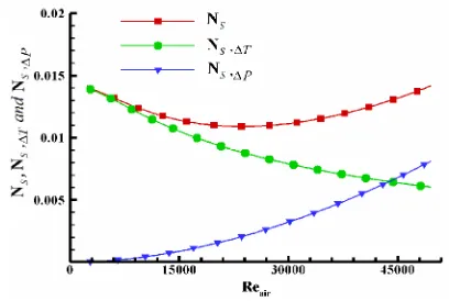
As already mentioned, heat transfer caused by temperature difference and pressure drop caused by fluid friction, are two factors which are producing irreversibility. Heat transfer coefficient increases with increasing the Reynolds number, which declines the temperature difference between hot and cold fluid in constant heat duty. This is the reason of S&gen,∆T
reduction with increase of Reynolds number. Any increase in the Reynolds number, resulting extra pressure drop and it gives higherS&gen,∆P. Therefore, the Reynolds number has two different effects on the amount of entropy generation number, so one can expect that for the minimum entropy generation number there would be an optimum Reynolds number. Hence, the optimum operating conditions occurs when the entropy generation number reaches its minimum value. In the next section, a full discussion will be presented.
4. VALIDATION AND OPYIMIZATION METHOD
To reduce the irreversibility losses in a heat exchanger, the entropy generation number throughout the heat exchanger should be minimized. For this purpose,
EES3code is developed using Equations (1)-(13) and the entropy generation number computed for various air flow rates. Results of this code with the lengths of 200 to 920 mm have been validated with experimental results of reference 11. As can be seen in Figure 2, the calculated values for Ns fit well with the values
reported in [14]. However, in L=200 mm, the results of the experimental values are slightly different, which can be related to the low number of fins. Because the equation which is used to calculate the friction factor is assumed to be true for large number of fins. Since one of the most important parameters affecting the performance of the heat exchanger is geometrical dimensions of theheat exchanger, so by changing the arrangement of the fins we can minimize the entropy generation. It should be noted that any change in the longitudinal and transversal pitch of the fins can affect the overlapping of them. To avoid pins overlapping, dimensionless parameters are introducedas follows:
2 2 ) 2 ( T L L S S D CR + = (14) out in d D N CR , π
θ = × (15)
where,din,outis outer diameter of inner pipe and N is the number of pins in each section. CRLandCRθ indicate longitudinal and transversal compact ratios of pins, respectively. Their maximum value is 1 which means that the heat exchanger tends to be more compact. Therefore, to avoid pins overlapping, two constraints
1
CRL< and CRθ <1 must be applied simultaneously.
To determine the minimum value ofNs, optimization
with two degrees of freedom ST and SL is considered.
Using Inverse parabolic interpolation method and the Golden section method are common in minimization algorithms. In the inverse parabolic interpolation method, The formula for the abscissa x that is the minimum of a parabola through three points f(a), f(b), and f(c) is calculated as follows:
)] ( ) ( )[ ( )] ( ) ( )[ ( )] ( ) ( [ ) ( )] ( ) ( [ ) ( 2 1 2 2 a f b f c b c f b f a b a f b f c b c f a f a b b x − − − − − − − − − − − = (16)
Inverse parabolic interpolation method has a second order convergence. However, performance is often quite poor if we do not start very close to the actual minimum point. For instance, if by any chance three of the function values f(a), f(b), and f(c) coincide, in which case the denominator is zero, the algorithm fails completely [18]. Thus, inverse quadratic interpolation is seldom used as a stand-alone algorithm. In this paper,
Brent’s method is used to combine inverse parabolic interpolation and the Golden section method which is linear and stable than inverse parabolic interpolation method [19]. In Brent's method, the optimization began with the same interval of uncertainty is used with the golden section method, but some additional points are computed. A quadratic function is then fitted to these points and the minimum of the quadratic function is computed using Equation (16).
If this minimum is within the appropriate interval of uncertainty, it is used in the next stage of the search and a new quadratic approximation is performed. If the minimum falls outside the known interval of uncertainty, then a step of the golden section search is performed. Hence, this algorithm uses both above methods advantages and it does not need computation of the derivatives.
5. RESULTS AND DISCUSSION
Variation of entropy generation number Ns versus the air Reynolds number Reair, for L=0.6 (m) is shown in Figure 3. Also, note that Reair is evaluated based on hydrodynamic diameter of double pipes. As it can be seen, by increasing in Reynolds number, entropy generation due to the pressure drop continuously grows. Pressure entropy generation will grow by increasing the Reynolds number which causes the pressure drop along the heat exchanger. (see Equation (8)). This indicates that any increase in Reynolds number yields extra pumping power. On the other hand, entropy generation due to temperature differences decreases with increase of Reynolds number. Exergy losses due to heat transfer caused by temperature difference emerge on low Reynolds numbers, where it is associated with low pressure drop losses. Against this fact, at high Reynolds numbers it occurs vice versa. So, an optimum Reynolds number exists with lowest total entropy generation number.Variation of irreversibility distribution ratio and
Bejan number for several lengths of heat exchanger are plotted in Figure 4.
For further clarity, the results of the five different configurations are detailed in two separate figures. Note that the results for L=920 mm are presented in both figures to facilitate easy comparisons between the results of all cases. From Figure 4a, it can be seen that in the constant Reynolds number by increasing the length of heat exchanger the irreversibility distribution ratio will be increased. However, in Figure 4b the effect of length is reverse. In other words, in the low length of heat exchanger and constant Reynolds number, irreversibility distribution ratio decreases and the Bijan number increases by increasing heat exchanger length.
And in lengths greater than a certain value, this behavior would be reversed. To elaborate this treatment, Figure 5 is presented. In this figure, entropy generation values of pressure and temperature are shown separately for different lengths. By connecting the intersection of each couple of irreversibility in the same length, the marginal curve will be obtained. Based on this diagram three regions can be considered: temperature dominant area, pressure dominant area and marginal curve. Points on the marginal curve represent a region with identical
T gen
S& ,∆ and S&gen,∆P. Note that there is a critical Reynolds
number, which for Re>Recr, S&gen,∆Palways be greater
thanS&gen,∆T. This point confirms that after a certain
value of Reynolds number and for each length of heat exchanger, pressure drop loss is the mainly irreversibility reason and temperature difference effect will be weak. Results of pin fin heat exchanger optimization for constant heat duty are reported in Table 1. Entropy generation number decreases for all cases in this table. This means optimization of current heat exchanger leads to decrease in Reynolds number and total pin numbers in all heat exchanger’s length. Low Reynolds number means a reduction in pumping power and fewer number of fins leads to lower construction costs.
a b
Figure4. Variation of irreversibility distribution ratio and Bejan number for several lengths of heat exchanger
Figure 5. Temperature dominant area, pressure dominant area and marginal curve
TABLE1. Optimized values of SL and ST for the current heat exchange
L [mm]
Q [W]
ST,opt
[mm]
SL,opt
[mm]
Npin
[14]
Npin,opt current
work
Ns
[14]
Ns,opt current
work
Reair
[14]
Reopt current
work
200 221 4.99 2.78 4563 3204 0.00497 0.004706 29046 19898 400 447 5.22 2.63 9125 6476 0.00837 0.008257 27794 22282 600 660 4.76 3.26 13688 8588 0.01091 0.010850 23621 17307 920 998 4.98 2.63 20988 18617 0.01321 0.01320 14440 11703
6. CONCLUSION
In this paper, numerical optimization of pin fin heat exchanger has been studied by the Bejan Method, which is based on examining entropy generation number Ns as a function of Re number. In addition, Sahiti et al. stated that for all investigated flow length, there is an optimal Re, which ensures a minimal NS. In this work, it has been shown that for each length of heat exchanger, a Reynolds number exists with the identical S&gen,∆T and
P gen
S& ,∆ , and critical Reynolds number was found, which for Re>Recr, S&gen,∆P will be greater thanS&gen,∆T (Figure
that finally, this will results in reduced manufacturing costs.
7. REFERENCES
1. DeylamiH.M., Amanifard N., Sanaei M., KouhikamaliR. and "Numerical investigation of heat transfer pressure drop in acorrugated channel", International Journal of Engineering Transactions A: Basics, Vol. 26, No. 7, (2013), 771-780. 2. Pussoli, B.F., Barbosa Jr, J.R., da Silva, L.W. and Kaviany, M.,
"Optimization of peripheral finned-tube evaporators using entropy generation minimization", International Journal of Heat and Mass Transfer, Vol. 55, No. 25, (2012), 7838-7846. 3. Bejan A., " Advanced engineering thermodynamics" ., (1988). 4. Bejan, A., "Entropy generation minimization: The method of
thermodynamic optimization of size systems and finite-time processes, CRC press, (1995).
5. Naphon, P., "Second law analysis on the heat transfer of the horizontal concentric tube heat exchanger", International Communications in Heat and Mass Transfer, Vol. 33, No. 8, (2006), 1029-1041.
6. Narayan, G.P., Lienhard, J.H. and Zubair, S.M., "Entropy generation minimization of combined heat and mass transfer devices", International Journal of Thermal Sciences, Vol. 49, No. 10, (2010), 2057-2066.
7. Guo, J., Cheng, L. and Xu, M., "Optimization design of shell-and-tube heat exchanger by entropy generation minimization and genetic algorithm", Applied Thermal Engineering, Vol. 29, No. 14, (2009), 2954-2960.
8. Ogulata, R. and Doba, F., "Experiments and entropy generation minimization analysis of a cross-flow heat exchanger",
International Journal of Heat and Mass Transfer, Vol. 41, No. 2, (1998), 373-381.
9. Hadidi, A., Hadidi, M. and Nazari, A., "A new design approach for shell-and-tube heat exchangers using imperialist competitive
algorithm (ica) from economic point of view", Energy Conversion and Management, Vol. 67, (2013), 66-74. 10. Yousefi M., Darus A. N., a.M.H. and “”, "Entropy generation
minimization in a plate fin heat exchanger by a social-political based evolutionary algorithm", International Conference on Advancements in Information Technology, IACSIT Press, Singapore., (2011).
11. Giangaspero, G. and Sciubba, E., "Application of the entropy generation minimization method to a solar heat exchanger: A pseudo-optimization design process based on the analysis of the local entropy generation maps", Energy, Vol. 58, (2013), 52-65. 12. Ghassabi, G. and Kahrom, M., "Optimization of heat transfer enhancement of a domestic gas burner based on pareto genetic algorithm: Experimental and numerical approach", International Journal of Engineering, Vol. 26, (2013), 211-230.
13. Amanifard, N., Hajiloo, A. and Tohidi, N., "Using neural networks and genetic algorithms for modelling and multi-objective optimal heat exchange through a tube bank",
International Journal of Engineering-Transactions C: Aspects, Vol. 25, No. 4, (2012), 321-230.
14. Sahiti, N., Krasniqi, F., Fejzullahu, X., Bunjaku, J. and Muriqi, A., "Entropy generation minimization of a double-pipe pin fin heat exchanger", Applied Thermal Engineering, Vol. 28, No. 17, (2008), 2337-2344.
15. Holman, J., "Heat transfer, 1986", Mc Gran–Hill Book Company, Soythern Methodist University, Vol., No., (1986). 16. Zukauskas, A., "Convective heat transfer in cross flow, Wiley,
New York, Vol. 6, (1987).
17. Yilmaz, M., Sara, O. and Karsli, S., "Performance evaluation criteria for heat exchangers based on second law analysis",
Exergy, an International Journal, Vol. 1, No. 4, (2001), 278-294.
18. Press, W.H., Teukolsky, S.A., Vetterling, W.T. and Flannery, B.P., Numerical recipes: The art of scientific computing (cambridge. 1992, Cambridge Univ. Press.
Optimization of Double Pipe Fin-pin Heat Exchanger using Entropy Generation
Minimization
M. Taghilou a, B. Ghadimib,M. H. Seyyedvalilua
aFaculty of Mechanical Engineering, University of Tabriz, Tabriz, Iran
bSchool of Mechanical Engineering, College of Engineering University of Tehran, Tehran, Iran
P A P E R I N F O
Paper history: Received 11 August 2013
Received in revised form 11 December 2013 Accepted in 22 May 2014
Keywords:
Double Pipe Heat Exchanger Fin-pin
Entropy Generation Optimization
هﺪﯿﮑﭼ
ﻠﺻاعﻮﺿﻮﻣ ﯽ اﯾ ﻦ ﻬﺑﻪﻟﺎﻘﻣ ﯿ ﻪﻨ زﺎﺳ ي دﺪﻋ ي ارآ ﯾ ﺶ ﺎﻫهﺮﭘ ي ﻧزﻮﺳ ﯽ ﻪﻟﻮﻟودلﺪﺒﻣ ا ي ﻣ ﯽ ﺪﺷﺎﺑ . ﺪﺑ ﯾ ﻦ درﻮﻣلﺪﺒﻣرﻮﻈﻨﻣ
ﻫﺎﺳﻂﺳﻮﺗهدﺎﻔﺘﺳا ﯿﺘ
ﯽ ﻟواﻪﺳﺪﻨﻫناﻮﻨﻋﻪﺑنارﺎﮑﻤﻫو ﯿﻪ
ﺖﺳاﻪﺘﻓﺮﮔراﺮﻗﻪﻌﻟﺎﻄﻣدرﻮﻣ .
ﻫﺎﺳرﺎﮐرد ﯿﺘ ﯽ ﺛﺄﺗﻪﺑنارﺎﮑﻤﻫو ﯿﺮ
ﭼهﻮﺤﻧ ﯿ نﺎﻣﺪ هﺮﭘ ﻞﺧادردﺎﻫ ﻻﺪﺒﻣ
هرﺎﺷ ا ي ﺖﺳاهﺪﺸﻧ . ازا ﯾ ﻦ نآلﺪﻣحﻼﺻاور ﻐﺗسﺎﺳاﺮﺑﺎﻫ
ﯿﯿ ﺮ ﭼ ﯿ نﺎﻣﺪ هﺮﭘ ﮑﺗﺎﺑ،ﺎﻫ ﯿﻪ ﺮﺑ
ﻤﮐمﻮﻬﻔﻣ ﯿ ﻪﻨ ﻟﻮﺗندﻮﻤﻧ ﯿﺪ ﭘوﺮﺘﻧآ ﯽ رﻮﮕﻟازاهدﺎﻔﺘﺳاو ﯾ
ﻢﺘ ﺖﺳاﻪﺘﻓﺮﮔمﺎﺠﻧاﺖﻧﺮﺑ .
ﺮﺿﺮﺑﺮﺛﻮﻣﻞﻣاﻮﻋ ﯾ
ﺐ ﺛﺄﺗ ﯿﺮ ﻪﻟدﺎﺒﻣ ﺎﻣﺮﮔﻦﮐ
ﻐﺘﻣﻪﺑﻪﺘﺴﺑاو ﯿﺮ
ﺎﻫ ي ﺪﻨﻫ ﺳ ﯽ دﺮﮑﻠﻤﻋتﺎﺼﺨﺸﻣو ي
ﻈﻧ ﯿﺮ ردﺪﻋ ﯾ زﺪﻟﻮﻨ ﺎﻣدو ي رﺎﮐ ي ﺖﺳا . ارد ﯾ ﻦ ﻦﺘﺷادﻪﮕﻧﺖﺑﺎﺛﺎﺑرﺎﮐ
ﺗراﺮﺣرﺎﺑ ﯽ هﺮﭘﺮﻄﻗو ﺎﻫ D ﻐﺗو ﯿﯿ ﺮ ﻟﻮﻃمﺎﮔ ﯽ ﺿﺮﻋو ﯽ ﻣﯿ نﺎ نآ ﻣ،ﺎﻫ ﯽ ناﻮﺗ ﻤﮐﺎﺑ ﯿ ﻪﻨ ﻟﻮﺗندﻮﻤﻧ ﯿﺪ ﭘوﺮﺘﻧآ ﯽ ، ﺎﺘﻧﻪﺑ ﯾ ﺠ ﯽ ﺮﺘﻬﺑ
ﺎﺘﻧزا ﯾ ﺞ ﻫﺎﺳ ﯿﺘ ﯽ ﺖﺳدﺶﻧارﺎﮑﻤﻫو ﯾ
ﺖﻓﺎ ﺘﻧﻪﮐ ﯿ ﻪﺠ ﺰﻫﺶﻫﺎﮐنآ ﯾ
ﻪﻨ ﺎﻫ ي ﻟﻮﺗ ﯿﺪ رﺎﺟو ي ﺖﺳا .
doi:10.5829/idosi.ije.2014.27.09c.13