R E S E A R C H
Open Access
Visualisation of the Bonebridge by means of
CT and CBCT
Christian Güldner
1*, Julia Heinrichs
2, Rainer Weiß
1, Annette Paula Zimmermann
1, Benjamin Dassinger
3,
Siegfried Bien
2, Jochen Alfred Werner
1and Isabell Diogo
1Abstract
Background:With the Bonebridge, a new bone-anchored hearing aid has been available since March 2012. The objective of the study was to analyse the visualisation of the implant itself as well as its impact on the representation of the bony structures of the petrosal bone in CT, MRI and cone beam CT (CBCT).
Methods:The Bonebridge was implanted unilaterally in two completely prepared human heads. The radiological imaging by means of CBCT, 64-slice CT, 1.5-T and 3.0-T MRI was conducted both preoperatively and postoperatively. The images were subsequently evaluated from both the ENT medical and nd radiological perspectives.
Results:As anticipated, no visualisation of the implant or of the petrosal bones could be realised on MRI because of the interactive technology and the magnet artefact. In contrast, an excellent evaluability of the implant itself as well as of the surrounding neurovascular structures (sinus sigmoideus, skull base, middle ear, inner ear, inner auditory canal) was exhibited in both the CT and in the CBCT.
Conclusion:The Bonebridge can be excellently imaged with the radiological imaging technologies of CT and CBCT. In the process, CBCT shows discrete advantages in comparison with CT. No relevant restrictions in image quality in the evaluation of the bony structures of the petrosal bones could be seen.
Keywords:Bonebridge, Digital volume tomography (DVT), Cone beam CT (CBCT), Computed tomography (CT), Bone-anchored hearing aid, Magnet resonance imaging (MRI)
Background
The question of the ideal hearing rehabilitation still remains unanswered. Conventional hearing aids, bone-conduction hearing aids, active and passive middle ear implants and cochlea implants as well as combinations of the previously mentioned aids are available. The field of bone-conduction hearing aids presents possibilities of vibration or energy transmission to the cranial calotte by means of pressing on the transducer via arms of glasses or headbands as well as direct anchoring in the bone (bone-anchored hearing aid, BAHA) [1-5]. The drawback of the latter systems is the interruption of the continuity of the skin. This can lead to a higher rate of skin infection as well as to restriction of the wearing comfort [6-14]. Moreover, good osseointegration of the inserted anchor is essential. Another existing system
(previously Otomag; subsequent model, Sophono Alpha 1), which leaves the skin intact, has so far not been widely dis-tributed [15].
A consequence of this has been the development of a par-tially implantable system based on the Vibrant Soundbridge with an audio processor positioned on the skin as well as an implant inserted subcutaneously and into the bone (in-tact skin technology) in the MedEl©facilities, which was in-troduced and exhibited officially as the Bonebridge©on the occasion of the ESPO 2012 in Amsterdam. The first im-plantations were performed in summer 2011, and the data on the initial market introduction studies show excellent audiological results with regard to both pure tone audiom-etry and language comprehension.
The introduction of new implants always leads to ques-tioning their visualisation by means of cross-sectional diag-nostic imaging as well as the impact of the implant on displaying the surrounding structures. For example, in the region of the ear, the bordering neurovascular and brain * Correspondence:[email protected]
1
University Hospital for ENT, Head and Neck Surgery, Baldingerstraße, 35043, UKGM, Marburg, Germany
Full list of author information is available at the end of the article
structures have to be respected as well as ideally further postoperative imaging of the mastoid with organs of the inner ear and structures of the middle ear without influen-cing the necessary safe diagnostic informational value in relation to these surrounding structures.
Therefore, the aim of this study was to test the visualisa-tion of the implant itself with convenvisualisa-tional radiological methods [computed tomography (CT), magnet resonance imaging (MRI), cone beam computed tomography (CBCT)] and to analyse the isolation capability to the surrounding structures of the cranial fossa. The influence of the implant on the visualisation of the surrounding brain structures in the different weightings of the MRI will be reproduced in a separate study for didactic reasons.
Methods
The Bonebridge© (MedEl, Innsbruck, Austria) was im-planted in two deceased body donors post-mortem. To achieve this, both completely prepared heads were freshly defrosted for the first time in order to obtain as accurate a reflexion of the reality of skin flexibility and bone struc-ture as possible. For the estimation of the anatomical structures (sinodural angle, pneumatisation, thickness of the calotte), a CBCT examination (Accu-I-tomo F17, Morita, Kyoto, Japan) was carried out prior to the surgical intervention. Hence, it was possible to plan the desired position of the implant.
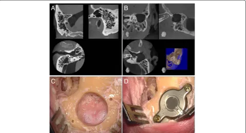
The intention was to simulate a classical surgery in the first skull (normal mastoid) (Figure 1A). This was car-ried out by a retroauricular skin incision parallel to the external ear fold and the preparation of the palva flap. After undermining the periosteum using a raspatorium, it was possible to prepare an adequate pocket as well as to gain an adequate view of the mastoid. The dummy of the ferro-magnetic transducer, the “Bone Conduction-Floating Mass Transducer”(BC-FMT), was positioned in the desired location and marked. The transmission of the radiological planning to the actual surface anatomy proved to be far from a trivial matter. This was followed by the preparation of the mastoid using a sharp drill. Under regular control using the dummy, a correct cylinder with regard to shape and depth was prepared (Figure 1C). In the process, an immediate positional relation to the sinus sigmoideus was shown in the posterior area, how-ever, without injury to its soft tissue casing. The drilling of the holes for the screws was no problem because of the disposable drill with a depth stop included in the delivery. The insertion of the bone conduction implant and the in-sertion of the magnet into the periosteum pocket also did not present any difficulty. The fixation of the screws using the provided torque wrench did not present any problems (Figure 1D).
In the second skull, the objective was to simulate the potential application in patients following cholesteatoma
Figure 1Preoperative CBCT (A and B) and intraoperative images (C and D).Preoperative radiological visualisation by CBCT of the site in the case of a well-pneumatised and not pre-operated mastoid(A)as well as a site with prior surgery in terms of a transcanalicular partial
surgery. To achieve this purpose, a transcanalicular antro-partial mastoidectomy was performed (Figure 1B) for res-toration (analogous to the extirpation for example of an extended epitympanalis cholesteatoma following the retro-auricular incision). The above-mentioned CBCT imaging was then conducted in order to determine the aspired pos-ition of the BC-FMT in this case also. As a result of the previously undertaken surgical steps, the transmission of the position to the surgical site proved to be easier in this case. This was followed by the implantation of the system in the above-described manner. Also in this site, it came in close positional relation to the dura and sinus sigmoideus without injury.
Following the successful implantation, the above-men tioned CBCT device was used for new imaging under the setting parameters established in the course of the daily routine (360° rotation, 84 kV, 8 mA, CTDI = 7.6 mGy) of the implanted ear (target volume of the cylinder: 6 cm height, 6 cm diameter). Furthermore, this was fol-lowed by the radiological examination using an in-house CT device (64-slice CT, Siemens, Erlangen, Germany).
Both the skulls were likewise subjected to the follow-ing magnetic resonance tomographic (MRI) examinations following the implantation. First, the Siemens Verio whole-body scanner with 3-T field strength with the standard
12-channel head coil (Siemens Healthcare, Erlangen, Germany) and second the Siemens Avanto whole-body scanner with 1.5-T field strength with the standard 12-channel head coil (Siemens Healthcare, Erlangen, Germany) were used. All radiological examinations were performed pre-and postoperatively.
Results
The position of the implant was determined under exact evaluation of the preoperative CBCT images, whereby the transmission to the actual surgical site was not easy. This was because of the lack of reproducible transfer of the surface structure from imaging to the anatomic situ-ation. One solution and improvement would be to take a navigation system to obtain better matching of imaging and the situation in the operating room. The possibility to insert a BC-FMT 3D template into a volume model of the individual site based on DICOM data allows the pre-operative visualisation of the exact location in relation to the anatomical landmarks, whereby the transmission of the planning to the actual intraoperative situation contains hidden sources of error. The surgical steps could be com-pleted quickly and easily under the supervision of the in-structors from MedEl©. Hence, it was possible to implant Bonebridges in both prepared skulls.
The imaging (CBCT, CT, MRI) was conducted in ac-cordance with the above-defined protocol. No problems were indicated such as dislocation of the implant or of the magnet and coil in MRI in particular. In the clinical evaluation after the conducted MRI examinations (ap-proximately 4 h scanning time for each skull because of the different scanning protocols with the 1.5- and 3.0-T MRI), the implant was shown to be in the same position as before. Functional testing was not performed because of the application of a test implant that was not com-pletely operational. As anticipated, during the analysis of the MRI images, the implant itself could not be evalu-ated and was not displayed because of complete and ex-cessive artefact radiation.
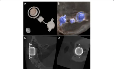
Visualisation of the Bonebridge was easily possible (Figure 2A and B) in both CT and CBCT. Due to the tech-nical prerequisites of CBCT (low target volume, high spatial resolution), it was possible to realise both the struc-ture of the implant itself and the exact visualisation of the fixing screws (Figure 2C and D).
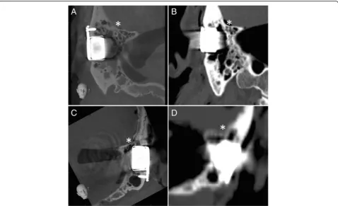
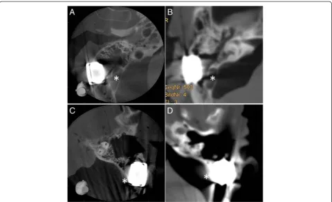
The analysis of the images in relation to the positional relation of the implant in the bone as well as to the border-ing neurovascular structures (posterior cranial fossa, sinus sigmoideus) could basically be conducted in both CT and CBCT (Figures 3 and 4). The image quality, however,
showed differences in quality in favour of CBCT. In both the representation of the base of the skull (Figure 3) and the demarcation to the sinus sigmoideus (Figure 4), fewer artefacts and a higher level of image intensity were realised. On observation of the further otoneurologically relevant structures (semicircular canals, inner ear, inner auditory canal), there was no relevant difference in CBCT and CT in the comparison of the pre- and postoperative implantation imaging data.
Discussion
Ongoing studies with regard to comparison of different bone-conduction hearing aids should demonstrate the re-spective differential indications. The focus of the current study was the radiological visualisation of the new implant as well as its impact on the imaging of the bony structures in the vicinity of the laterobase.
CT, CBCT and MRI are all currently used in daily cross-sectional imaging diagnostics in the field of ENT medi-cine. Hence, the question arises for the visualisation of every new implant in the region of the petrosal bone in the three modalities. CT has so far been the gold standard for imaging of the bony structures of the laterobase/petro-sal bone. Likewise, CT is the diagnostic choice for queries concerning the neurovascular structures around the
Figure 3Positional relation of the implant to the posterior cranial fossa.Visualisation of the implants in CBCT(AandC)and in CT(BandD)
implant following the implantation of active implants in the middle or inner ear. CBCT has become increasingly popular in recent years and has been able to show its pos-sibilities in both the visualisation of the laterobase [16-21] and below the frontonasal region [22-26], thus meanwhile presenting an alternative to CT in displaying of bony structures [27].
In this study, it has been possible to generate represen-tative images for displaying the implant itself in CT and CBCT. As anticipated, an artefact-caused overlapping of the implant is shown on MRI, meaning that no visualisa-tion of the implant or the directly bordering anatomical structures was possible. Excellent visualisation of the 3D structure of the implant was achieved in both CT and CBCT. A good presentation of the surrounding, surgically significant anatomical structures (inner ear, semicircular canals, inner auditory canal, rear skull base, sinus sig-moideus) were also shown, whereby in the case of CBCT, the image quality in relation to the bony structures tended to be better. All in all, a visualisation around the implant is possible in both modalities, meaning that in the case of a new surgical intervention in the region of the petrosal bone, statements relating to the anatomical circumstances can be made and therefore preoperative planning can be achieved. A big advantage of CT in combination with contrast media
is the possibility of visualisation of soft tissues. Therefore, CT could be an alternative to MRI, where the inner audi-tory canal is overlapped by artefacts, in visualisation of the bony and soft tissue structures of the inner auditory canal in case of radiological control after implantation in case of hearing loss after diseases of this structure (e.g. acoustic neuromas).
Conclusion
This is the first study describing the radiological aspects of the brand-new bone-conducting implant“Bonebridge”. Visualisation of the implant itself and the surrounding anatomical structures is possible with CT and CBCT as well. Regarding imaging quality, CBCT shows advantages in comparison to conventional CT.
Abbreviations
BAHA:Bone-anchored hearing aid; BC-FMT: Bone conduction-floating mass transducer; CBCT: Cone beam computed tomography; CT: Computed tomography; CTDI: Computed tomography dosage index; DVT: Digital volume tomography; ESPO: European Society of Paediatric Otolaryngology; ENT: Ear-nose-throat; MRI: Magnet resonance imaging.
Competing interests
The authors declare that they have no competing interests.
Authors’contributions
CG planned the study, carried out the operations, accompanied the imaging and wrote the manuscript. JH carried out the imaging procedures of CT. RW participated in the study design and at operating procedures. AZ
participated at CBCT imaging, BD carried out the MR imaging, SB participated at CT imaging, JAW participated in the study design and coordination. ID carried out the CBCT imaging procedures and helped to draft the manuscript. All authors read and approved the final manuscript.
Author details
1University Hospital for ENT, Head and Neck Surgery, Baldingerstraße, 35043,
UKGM, Marburg, Germany.2University Hospital for Neuroradiology, UKGM, Marburg, Germany.3University Hospital for Neuroradiology, UKGM, Gießen, Germany.
Received: 15 April 2013 Accepted: 19 August 2013 Published: 3 September 2013
References
1. Cremers CW, Snik FM, Beynon AJ:Hearing with the bone-anchored hearing aid (BAHA, HC 200) compared to a conventional bone-conduction hearing aid.Clin Otolaryngol Allied Sci1992,17:275–279. 2. Hol MK, Cremers CW, Coppens-Schellekens W, Snik AF:The BAHA
Softband: a new treatment for young children with bilateral congenital aural atresia.Int J Pediatr Otorhinolaryngol2005,69:973–980.
3. Snik AF, Mylanus EA, Proops DW, Wolfaardt JF, Hodgetts WE, Somers T, Niparko JK, Wazen JJ, Sterkers O, Cremers CW, Tjellstrom A:Consensus statements on the BAHA system: where do we stand at present?
Ann Otol Rhinol Laryngol Suppl2005,195:2–12.
4. Verhagen CV, Hol MK, Coppens-Schellekens W, Snik AF, Cremers CW:The Baha Softband: a new treatment for young children with bilateral congenital aural atresia.Int J Pediatr Otorhinolaryngol2008,72:1455–1459. 5. Federspil PA:[Bone anchored hearing aids (BAHA)].HNO2009,57:216–222. 6. Siau D, Nik H, Hobson JC, Roper AJ, Rothera MP, Green KM:Bone-anchored
hearing aids and chronic pain: a long-term complication and a cause for elective implant removal.J Laryngol Otol2012,126:445–449.
7. Ricci G, Della Volpe A, Faralli M, Longari F, Gulla M, Mansi N, Frenguelli A:
Results and complications of the Baha system (bone-anchored hearing aid).Eur Arch Otorhinolaryngol2010,267:1539–1545.
8. Doshi J, Karagama Y, Buckley D, Johnson I:Observational study of bone-anchored hearing aid infection rates using different post-operative dressings.J Laryngol Otol2006,120:842–844.
9. De Wolf MJ, Hol MK, Mylanus EA, Cremers CW:Bone-anchored hearing aid surgery in older adults: implant loss and skin reactions.Ann Otol Rhinol Laryngol2009,118:525–531.
10. Monksfield P, Chapple IL, Matthews JB, Grant MM, Addison O, Reid AP, Proops DW, Sammons RL:Biofilm formation on bone-anchored hearing aids.J Laryngol Otol2011,125:1125–1130.
11. Wazen JJ, Wycherly B, Daugherty J:Complications of bone-anchored hearing devices.Adv Otorhinolaryngol2011,71:63–72.
12. Gluth MB, Eager KM, Eikelboom RH, Atlas MD:Long-term benefit perception, complications, and device malfunction rate of bone-anchored hearing aid implantation for profound unilateral sensorineural hearing loss.Otol Neurotol2010,31:1427–1434.
13. Hobson JC, Roper AJ, Andrew R, Rothera MP, Hill P, Green KM:
Complications of bone-anchored hearing aid implantation.J Laryngol Otol2009,124:132–136.
14. Zeitler DM, Herman BS, Snapp HA, Telischi FF, Angeli SI:Ethnic disparity in skin complications following bone-anchored hearing aid implantation.
Ann Otol Rhinol Laryngol2012,121:549–554.
15. Siegert R:Partially implantable bone conduction hearing aids without a percutaneous abutment (Otomag): technique and preliminary clinical results.Adv Otorhinolaryngol2011,71:41–46.
16. Offergeld C, Kromeier J, Aschendorff A, Maier W, Klenzner T, Beleites T, Zahnert T, Schipper J, Laszig R:Rotational tomography of the normal and reconstructed middle ear in temporal bones: an experimental study.
Eur Arch Otorhinolaryngol2007,264:345–351.
17. Offergeld C, Kromeier J, Merchant SN, Lasurashvili N, Neudert M, Bornitz M, Laszig R, Zahnert T:Experimental investigation of rotational tomography in reconstructed middle ears with clinical implications.Hear Res2009,
263:191–197.
18. Kurzweg T, Dalchow CV, Bremke M, Majdani O, Kureck I, Knecht R, Werner JA, Teymoortash A:The value of digital volume tomography in assessing the position of cochlear implant arrays in temporal bone specimens.Ear Hear 2011,31:413–419.
19. Teymoortash A, Hamzei S, Murthum T, Eivazi B, Kureck I, Werner JA:
Temporal bone imaging using digital volume tomography and computed tomography: a comparative cadaveric radiological study.
Surg Radiol Anat2011,33:123–128.
20. Dalchow C, Weber A, Bien S, Yanagihara N, Werner J:Value of digital volume tomography in patients with conductive hearing loss.
Eur Arch Otorhinolaryngol2006,263:92–99.
21. Dalchow CV, Weber AL, Yanagihara N, Bien S, Werner JA:Digital volume tomography: radiologic examinations of the temporal bone.
AJR Am J Roentgenol2006,186:416–423.
22. Güldner C, Diogo I, Windfuhr J, Bien S, Teymoortash A, Werner JA, Bremke M:
Analysis of the fossa olfactoria using cone beam tomography (CBT).
Acta Otolaryngol2011,131:72–78.
23. Güldner C, Ningo A, Voigt J, Diogo I, Heinrichs J, Weber R, Wilhelm T, Fiebich M:Potential of dosage reduction in cone-beam-computed tomography (CBCT) for radiological diagnostics of the paranasal sinuses.
Eur Arch Otorhinolaryngol2012,270(4):1307–1315.
24. Güldner C, Pistorius SM, Diogo I, Bien S, Sesterhenn A, Werner JA:Analysis of pneumatization and neurovascular structures of the sphenoid sinus using cone-beam tomography (CBT).Acta Radiol2012,53:214–219. 25. Bremke M, Sesterhenn AM, Murthum T, Al Hail A, Bien S, Werner JA:Digital
volume tomography (DVT) as a diagnostic modality of the anterior skull base.Acta Otolaryngol2009,129:1106–1114.
26. Bremke M, Wiegand S, Sesterhenn AM, Eken M, Bien S, Werner JA:Digital volume tomography in the diagnosis of nasal bone fractures.
Rhinology2009,47:126–131.
27. Majdani O, Thews K, Bartling S, Leinung M, Dalchow C, Labadie R, Lenarz T, Heidrich G:Temporal bone imaging: comparison of flat panel volume CT and multisection CT.AJNR Am J Neuroradiol2009,30:1419–1424.
doi:10.1186/2047-783X-18-30
Cite this article as:Güldneret al.:Visualisation of the Bonebridge by means of CT and CBCT.European Journal of Medical Research201318:30.
Submit your next manuscript to BioMed Central and take full advantage of:
• Convenient online submission
• Thorough peer review
• No space constraints or color figure charges
• Immediate publication on acceptance
• Inclusion in PubMed, CAS, Scopus and Google Scholar
• Research which is freely available for redistribution