OBJECT ORIENTED CONDENSED GRAPHS∗
SUNIL JOHN AND JOHN P. MORRISON†
Abstract. Even though Object Orientation has been proven to be an effective programming paradigm for software development, it has not been shown to be an ideal solution for the development of large scale parallel and distributed systems. There are a number of reasons for this: the parallelism and synchronisation in these systems has to be explicitly managed by the programmer; few Object Oriented languages have implicit support for Garbage Collection in parallel applications; and the state of a systems of concurrent objects is difficult to determine. In contrast, the Condensed Graph model provides a way of explicitly expressing parallelism but with implicit synchronisation; its implementation in the WebCom system provides for automatic garbage collection and the dynamic state of the application is embodied in the topology of the Condensed Graph. These characteristics free programmers from the difficult and error prone process of explicitly managing parallelism and thus allows them to concentrate on expressing a solution to
the problem rather than on its low level implementation. Object Oriented Condensed Graphsis a computational paradigm
which combines Condensed Graphs with object orientation and this unified model leverages the advantages of both paradigms. This paper illustrates the basic features of Object Oriented Condensed Graphs as well as its support for large scale software development.
Key words: condensed graphs, object oriented systems, software engineering, distributed and parallel computing
1. Introduction. The support of large scale software systems has long been the focus of research in software engineering. Object Oriented Systems have attracted wide attention due to its many desirable prop-erties which aid software development such as enhanced maintainability and reusability. With the support of characteristics such as inheritance, modularity, polymorphism and encapsulation, this paradigm can help the development of complex software programs [17]. However, the development of parallel and distributed appli-cations is not significantly simplified by Object Orientation. The onus is still on the programmer to explicitly manage each parallel component and to ensure proper synchronisation. The interaction of parallel components in a large system can be complex and this complexity is compounded in sophisticated environments such as heterogeneous clusters and computational grids. Moreover, the encapsulation concept in OO is complex in a parallel environment. OO does not impose constraints upon invocation of an object’s attributes or mem-ber functions. This complicates the relationship among objects when there are several method invocations. Similarly, memory management is a major concern. Most of the current Garbage Collection methodologies work sequentially; only a few OO languages can support automatic garbage collection in a parallel system. In addition, parallelism poses additional challenges for access control mechanisms and object state determination. The Condensed Graph (CG) model of computing is based on Directed Acyclic Graphs (DAGs). This model is language independent and it unifies the imperative, lazy and eager computational models [2]. Due to its features including Implicit Synchronisation and Implicit Garbage Collection this computational model can be effectively deployed in a parallel environment. CGs have been employed in a spectrum of application domains, from FPGAs to the Grid [7, 4]. The most advanced reference implementation of the model is the WebCom abstract machine [5]. WebCom is being used as the basis of Grid-Ireland’s middleware development and deployment [3].
This paper addresses the concept of Object Oriented Condensed Graphs (OOCG) as well as its development support in a large scale environment. Object Oriented Condensed Graphs is a unified model that combines the Object Oriented paradigm with the Condensed Graph methodology. This unified model helps to leverage the advantages of both paradigms. By integrating Condensed Graphs with Object Oriented principles, negative aspects of Object Orientation, when deployed in a large scale parallel environment, can be successfully addressed.
Some of the similar research in this area of modelling languages are Object Oriented Petri Nets (OOPN) [8] and Object Petri Nets (OPN) [9, 10, 11] in which the Object Orientation principles has combined with that of Petri Nets [13]. Other notable Petri Net modelling languages embodying OO concepts are CPN [12], HOOPN [14] and CO-OPN [15, 16].
This paper is organised as follows: Section 2 provides an overview of Condensed Graphs, and Section 3 presents the basics of Object Oriented Condensed Graphs. Section 4 presents Development support, particularly pattern based OOCG Development, as well as its performance analysis.
∗The support of Science Foundation Ireland is gratefully acknowledged.
†Centre for Unified Computing, Dept. of Computer Science, National University of Ireland, University College Cork, Cork,
Ireland (s.john,[email protected]). http://www.cuc.ucc.ie
2. Condensed Graphs. Like classical dataflow, the CG model is graph-based and uses the flow of entities on arcs to trigger execution. In contrast, CGs are directed acyclic graphs in which every node contains not only operand ports, but also an operator and a destination port. Arcs incident on these respective ports carry other CGs representing operands, operators and destinations. Condensed Graphs are so called because their nodes may becondensations, or abstractions, of other CGs. (Condensation is a concept used by graph theoreticians for exposing meta-level information from a graph by partitioning its vertex set, defining each subset of the partition to be a node in the condensation, and by connecting those nodes according to a well-defined rule.) Condensed Graphs can thus be represented by a single node (called a condensed node) in a graph at a higher level of abstraction. The number of possible abstraction levels derivable from a specific graph depends on the number of nodes in that graph and the partitions chosen for each condensation. Each graph in this sequence of condensations represents the same information but in a different level of abstraction. It is possible to navigate between these abstraction levels, moving from the specific to the abstract through condensation, and from the abstract to the specific through a complementary process called evaporation.
5
f
g
f 5
g
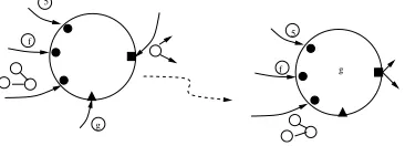
Fig. 2.1.CGs congregating at a node to form an instruction.
The basis of the CG firing rule is the presence of a CG in every port of a node. That is, a CG representing an operand is associated with every operand port, an operator CG with the operator port and a destination CG with the destination port. This way, the three essential ingredients of an instruction are brought together (these ingredients are also present in the dataflow model; only there, the operator and destination are statically part of the graph).
Any CG may represent an operator. It may be a condensed node, a node whose operator port is associated with a machine primitive (or a sequence of machine primitives) or it may be a multi-node CG.
The present representation of a destination in the CG model is as a node whose own destination port is associated with one or more port identifications. Figure 2.1 illustrates the congregation of instruction elements at a node and the resultant rewriting that takes place.
Strict operands are consumed in an instruction execution but non-strict operands may be either consumed or propagated. The CG operators can be divided into two categories: those that are value-transforming and those that only move CGs from one node to another in a well-defined manner. Value-transforming operators are intimately connected with the underlying machine and can range from simple arithmetic operations to the invocation of software functions or components that form part of an application. In contrast, CG moving instructions are few in number and are architecture independent.
By statically constructing a CG to contain operators and destinations, the flow of operand CGs sequences the computation in a dataflow manner. Similarly, constructing a CG to statically contain operands and opera-tors, the flow of destination CGs will drive the computation in a demand-driven manner. Finally, by constructing CGs to statically contain operands and destinations, the flow of operators will result in a control-driven evalu-ation. This latter evaluation order, in conjunction with side-effects, is used to implement imperative semantics. The power of the CG model results from being able to exploit all of these evaluation strategies in the same computation, and dynamically move between them using a single, uniform, formalism.
3. Object Oriented Condensed Graphs. The Object Oriented Condensed Graphs paradigm, OOCG, has been developed to address the limitations of Object Oriented Systems mentioned in Section 1. As a unified model, Object Oriented Condensed Graphs preserves all the current functionalities of Condensed Graphs while featuring many major Object Oriented Concepts. The core features and functionalities are given below [1]:
method A
method m . . . Class X
X E
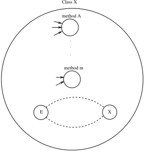
Fig. 3.1.A Node to represent Class X. The member functions form child nodes within that node.
o2 o3 o1
X
Y
Fig. 3.2.Invoking Object X with Operands. Sending the result to Y.
In the CG model, Graph instance creation can occur implicitly when an appropriate CG node is invoked. Alternatively, explicit instance creation will give rise, not only to an appropriate graph instance but also, to a CG node which can be used to represent that instance. In effect, these nodes are coherent names of dynamically created objects.
OOCG specifies two kinds of visibility for its member functions and attributes. As is typical in an Object Oriented language, private members belonging to an Object can be accessed only within that Object. In contrast, apublicmember has a broad visibility. It can be accessed from inside as well as from outside of that Object. In other words, it has aGlobal Scope. Some of these scenarios are shown in Figs. 3.1, 3.2 and 3.3.
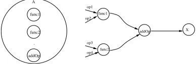
3.2. Inheritance in Condensed Graphs. Object Oriented Condensed Graphs incorporatesingle inher-itance. A Class can inherit from other classes. In this way, a sub class can inherit the properties of itssuper class. The sub class can introduce new properties or can override the inherited properties of its super class. As shown in Figs. 3.4 and 3.5, subclassClass Bextends superclassClass A. By default, public members of A are available in Class B and these can be used for operations within B.
The class definitions can be instantiated as Objects. The characteristics of Polymorphism also can be observed in the class instances. By overriding the parent class operation in the child class, the behaviour can be changed in the sub class. In the above example, we can redefine the member functionfunc1in the sub class so that the whole operation behaviour can be redefined. This also gives risesdynamic binding. During compile time the contexts between the operations can be switched.
X.A o1 o2 o3
Y
Fig. 3.3.Invoking Method A of Object X with Operands. Sending the result to Y.
func1
func2 op2
op1
op4 op3
addOp X
A
func1
func2
.
addOp
Fig. 3.4.The parent super class A.
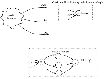
A new graph model to support access to shared resources is proposed in Figure 3.6. Many operands may converge to the E node of this graph. A priority based queuing mechanism is employed in the E node to handle these accesses and a local semaphore is used to enforce sequential access to the underlying graph. Typically it sets a flag when it allows the invocation of the graph. When the X node of the graph fires this flag reverts back to its previous value.
3.4. Explicit Naming Scheme. OOCG Node names adapt from the code semantics. A Class Node bear the name of the Class in the program. A Class method name is normally preceded by a colon. As an example, the Nodes C and C:getDetails illustrate Class C and the method getDetails within class C respectively. Inheritance and the nested class scenarios also can be incorporated. The Node annotationA.B.C:getDetails
illustrates the member functiongetDetailsof the classC which is derived from base classesB andA. Some research regarding the naming scheme using the Condensed Graph model is addressed in [5].
3.5. Object Creation and Automatic Garbage Collection. Condensed Graphs support Object Cre-ation andImplicit Object Destructionor Automatic Garbage Collection [1]. Object Creation can be performed by invoking theCreateinstruction. This instruction takes the Class Definition as an input Operand and creates an Object as output. Figs. 3.7 and 3.8 illustrates some scenarios of the Object creation. Typically when an Object’s X Node fires the Object is collected automatically.
4. OOCG Development Support. OOCG development framework has been developed for the creation of OOCG applications for concurrent and distributed environments. OOCGLib is a programming package consisting of a set of Java classes and libraries to address integrated development. OOCGLib is integrated withW ebCom-GIDE [3] which allows developers to develop OOCG applications in an interactive, distributed
environment (Figure 4.1). This development environment is implemented as an application layer on top of the WebCom [5] middleware. As an integrated framework, it benefits from the features of WebCom such as load balancing, fault tolerance and security policies.
4.1. Multiphase Patterns. In modelling a system, patterns often used to efficiently express solution in a standard manner. Patterns are template solutions that have been developed to address common recurring problems in particular application domains.
Gamma et al. [18] suggested recurring solutions to common problems in design. They presented their ideas in the context of Object Oriented design. Le Guennec et al. [21] has incorporated some of this work on design patterns in UML using their customised tool UMLAUT. W.M.P. van der Aalst et al. suggestedWorkflow Patterns [22] as Requirements for workflow languages. Later research in this area has also addressed control flow patterns [23] and provided a formal description of each of them in the form of a Coloured Petri-Net (CPN) model.
op5
X func1
func3 B
A
func1
func2 .
func3
func4 .
Fig. 3.5.The child sub class B. The child class inherited the public contents of class A.
CG1
CG2
CG3
o1 o2
o3 CG1 Resource
Create
o2 o3 o1
E
Resource Graph
Condensed Node Refering to the Resource Graph
X X1 X2 X3
Fig. 3.6.The Condensed Nodes refer to the Resource Graph. The E node of the Resource Graph contains a local semaphore which restricts the access to resource one at a time.
lifecycle, from high level modelling to design, implementation and testing is currently missing from the software engineering landscape. The concept of a Multiphase pattern is presented here to address solutions to all phases of the software engineering lifecycle ranging from modelling, design to implementation.
Two Multiphase patterns, as part of the OOCG model, are presented in this paper to address common scenarios. These are design patterns which are being adapted and extended to cover multiple phases in the engineering lifecycle. Similar to the strategy adopted by Gamma et.al. [18], the OOCG Multiphase Patterns also name, motivate, and explain solutions for generic problems.
4.1.1. Predecessor-Successor Pattern. This pattern addresses the sequential execution of dependant tasks.
Name of the Pattern. Predecessor-Successor.
Related Patterns. Sequential Routing, Serial Routing [19]. In this Petri net based workflow pattern, a process wait for the other process for serial execution.
Motivation. In a concurrent system of dependent tasks, the order of execution of tasks is a matter of interest. As an example, if there are two dependent tasks and if any of the tasks requires a value that needs to be transferred from the other task, it is important to know their order of execution.
Description of the Problem. Consider two tasks G1 and G2. G2 expects a value X1 that needs to be
transferred from task G1. In this case, task G1 has to be executed first to produce the value X1.
Solution of the Problem. Induce the notion ofSequencingin the task modelling. If a task needs a value from another task, execute the first task prior to the second task. The value produced as a result of the execution of the first task is transferred to the second task.
Create
B B*
B* func1 ab
c
X
Fig. 3.7. In this Condensed Graph realisation, object B* has been created and is used to invoke the function func1with operands a,b and c.
func1 a b
c B*
E
a b
c
B*.func1 .
. X
E
E func1
B*
X
Fig. 3.8.Different CG scenarios for the Object creation.
Fig. 4.1.Sample Screen shot ofW ebCom-GIDE, showing the Graphs used to generate a Fibonacci sequence.
E X
X1
E X
Graph G1 Graph G2
E
PH_b.wait PH_b.takeforks PH_b.eat X Eat
X PH_a.requestforks PH_a.Think
E
Think
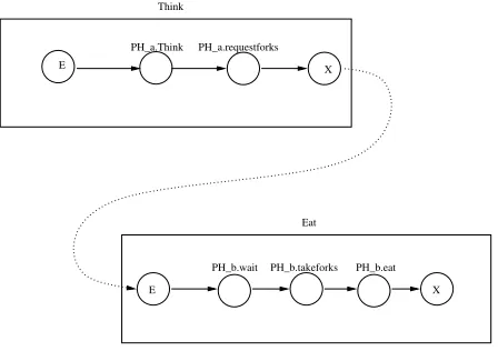
Fig. 4.3. GraphEatneeds to wait for graphThink.
G1 G2
G1
G2
(a) (b)
Fig. 4.4.(a) Connected dataflow graphs and (b) Non-connected Lazy graphs. In scenario (a), G2 needs to wait for G1. This scenario is applicable if the Operand port in G2 is strict. In scenario (b), G2 can start before G1 executes. The Operand port in G2is non-strict in this scenario. In the first case, G1is the Predecessor graph and G2 is the Successor graph. In the second case (b), G1becomes Successor and G2 becomes Predecessor.
Example. Consider the classical dining philosophers problem [20]. In this example, a group of philosophers sit around a table sharing one fork between each pair of philosophers. In this problem the forks are a shared resource and in order to eat a philosopher must have the two forks on either side of him/her. In Figure 4.3, graphEathas to wait for the value forkfrom the graphThink. As is evident from this scenario,Thinkacts as anPredecessorgraph whileEatas theSuccessorgraph.
Predecessor-Successor in OOCG. The sequencing of the execution of nodes in an OOCG may be lazy oreager. The actual order of evaluation is determined by the strictness of Node Operand Ports and the form of the Operand, i. e., whether the Operand is a normal order form or is in need of further reduction. An Eager evaluation sequence results when the operand ports of a node arenon-strictregardless of the form of the operands. When the operand ports arestrict, eager evaluation will result when the Operands is in normal order form and lazy Evaluation will be triggered when they are not in normal order form.
Figure 4.4 illustrates these two scenarios with tasks G1and G2. Figure 4.4 (a) depicts a strictscenario in
which the output of task G1is required for input of task G2. Task G2will not execute without this input. This
iseagermode of graph sequencing. In thenon-strictsense, illustrated in Figure 4.4 (b), task G1 represents the
operand of task G2. G2can be Predecessor in thislazyscenario. In certain cases, G1need not be evaluated at all.
In Figure 4.5, Multi-relationship between the graphs are depicted. In this case as well, strictness of the port determines Predecessor-Successor relationship.
In the Lazy way of graph sequencing in OOCG, Predecessor becomes Successor as the Successor becomes lazy. Thus, in lazy evaluation, Predecessor and Successor change their roles. The existence of Predecessor is used as the mechanism to drive the execution of Successor.
G1 G2
G3
Fig. 4.5. G1 is Predecessor to G3. If the port in G2 is strict, G3 and G1 are Predecessors to G2. Strictness of the port determines Predecessor-Successor relationship.
E X
o1
o2 o3
E X
E X
o1
o2 o3
o2 o3 o1
E X
Subject Graph G1
Graph G3 Graph G4
Graph G2
Observer Observer Observer
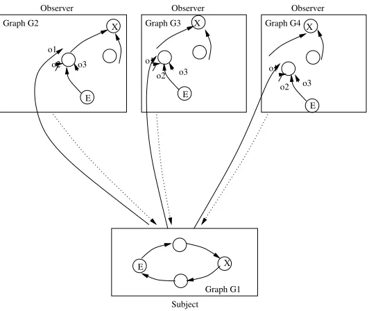
Fig. 4.6.Observer pattern. Subject GraphG1 notifies Observer Graphs G2,G3 andG4.
4.1.2. Multiphase Observer Pattern. This pattern is based on the Observer pattern [18] introduced by Gamma et al. Multiphase Observer Patternis an extended version of Observer pattern with Multiphase concepts. This is categorised as aBehavioural Pattern.
Name of the Patter. Multiphase Observer
Also Known As. Publish-Subscribe
Motivation. If there are multiple dependent tasks and if a task’s state change affects the state of other tasks it is important that there should be notification mechanism between the tasks so as to ensure a proper synchronisation.
Description of the Problem. Figure 4.6 illustrates the problem addressed by this pattern. Task G1 is
dependent on tasks G2, G3 and G4. The execution of task G1affects the decision making within the tasks G2,
G3and G4. A synchronisation mechanism is needed in this state change event.
Solution of the Problem. The task upon which other tasks are dependent is known as the Subject
and the dependent tasks which observes the state change event from the Subject are known as Observers. A Subject can have any number of Observers. Whenever a Subject’s state changes, it notifies its Observers. In response, each Observer synchronise its state with the Subject’s state.
S1
Obs1
Obs2
Obs3 S1
S2
S3
R (Registry) R (Registry)
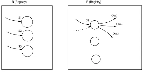
Fig. 4.7.OOCG implementation of Observer pattern. The node in the registry are created by the Subject to reflect the state elements. Observers register as destination nodes of the Subject. By registering, they become part of the destination of the state node.
E
1
S V1
X
Fig. 4.8.Subject graph. Value V1 is being sent to the State Node S1. V1 is deconstructed after State Node S1 is fired.
Examples. In the dining philosophers problem mentioned before, the task which holds the fork acts as the Subjectand the tasks which request forks act asObservers. When the Subject releases the fork, it notifies the Observers.
Observer Pattern in OOCG. In the OOCG adaptation of Observer pattern, the Subject-Observer relationship is maintained by means of registry mappings. The registry entry is created by the Subject. The nodes in the registry are created by the Subject to reflect the state elements.
Observers register destination nodes with the registry to be advised of change in state elements. By registering they become part of the destination of the appropriateState Node(Figure 4.7). In the Figure 4.7, Operand value V1must be passed onto the Observers. As Operator, Subject generates this value and Observer,
as destination, consumes this value. The Operator copies the Operand value to the destination.
In the Subject graph, there is a link from the state element to the Registry (Figure 4.8). The notification operands are deconstructed when the state node is fired. When the E node of the Observer graph fires, it registers destination nodes with Registry. Similarly, when its X node fires, it removes the destination link from the Registry.
The Subject-Observer state changes can be by means ofpushorpullmodel. In the push model, Operand value converge to the Subject and passes to the Observer destination. In the pull model, Operatorpulls the value from registry and send to the destination. After sending the value, the destination will be deconstructed. When a new Observer creates, it pulls the value from the registry. In thisPollingmechanism, new State value arrives and overrides the old value.
Ob-E
Analyse Results
X
Results X
E E
X
E
DCT Results
X E
X
X E
Calculate DCT
Analyse Results
Calculate DCT
Analyse Results
Calculate DCT
Analyse Results
Calculate Analyse
IDCT Calculate
Calculate IDCT
Analyse
Service A
Service B
Service C
(i) (ii)
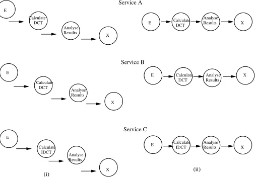
Fig. 4.9.Initial OOCG models. (i) Lazy version, and (ii) Eager version. Since the tasks are dependent with each other, Lazy scenario is not applicable here.
Service B
Service C Service B
Service A
Service A Service C (i)
(ii)
A
B
C Client
(iii)
(a) (b)
Service Hosts
Fig. 4.10. Some patterns implemented within the OOCG application. (a) Predecessor-Successor: (i) A-before-B, (ii) B-before-C, and (iii) A-before-C. (b) Observer Pattern. Client waits for the results from the Service Hosts.
server (Client) waits for results from the Subject (Service Hosts). These pattern implementations are shown in Figure 4.10.
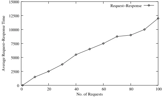
The performance of this setup has been observed by measuring the request-response interaction between Services. Performance is thus quantified as the average Request-Response time.
The experimental system is composed of three services and within each service, request to access other services are implemented as request threads. Similarly, responses also are implemented as response threads which will respond to the requests. The system can be fine-tuned by adjusting the number of concurrent requests. It can be observed from the experiments that the performancedecreaseswith the increasing number of concurrent requests. Figure 4.11 illustrates this experimental results.
0
0 5 10 15 20 25 30
Average Request−Response Time
No. of Requests
Request−Response
50 100 150 200 250 300 350 400
Fig. 4.11.Average Request-Response time with respect to the concurrent Requests.
0
0 20 40 60 80 100
Average Request−Response Time
No. of Requests
Request−Response
2500 5000 7500 10000 12500 15000
Fig. 4.12.Average Request-Response time by removing performance bottleneck.
5. Conclusions and Future Work. The contributions of this paper are the introduction of enhanced version of Condensed Graphs, Object Oriented Condensed Graphs, and its development support in a large scale environment. OOCG is a unified model that combines the Condensed Graphs methodology with object orientation and this leverages the advantages of both paradigms. This unified computational model is beneficial for the development of Large Scale Parallel Systems since the CG aspects allows the developer to think about parallelism and the Object Oriented aspects allow the developer to address the large scale concepts. OOCG provide implicit support of Synchronisation and Garbage Collection capabilities, which help the development of concurrent software. The Object concept and features such as Encapsulation and Inheritance enhance the Reusability and Maintainability of OOCG.
The existing implementation of Condensed Graphs has been extended to implement the OOCG features. Engineering practises have been proposed and implemented for its development in a large scale environment. OOCG model has been integrated into the Condensed Graph Integrated Development Environment,W ebCom -GIDE [3] which is a development tool that enables visual application development and optimisation. Using
the Integrated Development Environment, OOCG applications are created and deployed for concurrent and distributed environments.
REFERENCES
[1] Sunil John and John P. Morrison:Garbage Collection in Object Oriented Condensed Graphs,Springer-Verlag LNCS, 3rd Workshop on Large Scale Computation on Grids,LaSCoG 2007, held jointly with the 7th International Conference on
Parallel Processing and Applied Mathematics, Gda´nsk, Poland, September 9–12, 2007.
[2] John P. Morrison, Condensed Graphs: Unifying Availability-Driven, Coercion-Driven and Control-Driven Computing,
PhD Thesis, Eindhoven: 1996.
[3] John P. Morrison, Sunil John, David A. Power, Neil Cafferkey and Adarsh Patil:A Grid Application Development
Platform for WebCom-G,IEEE Proceedings of the International Symposium of the Cluster and Grid Computing,CCGrid
2005, Cardiff, United Kingdom.
[4] John P. Morrison, Brian Clayton, David A. Power and Adarsh Patil:WebCom-G: Grid Enabled Metacomputing,The Journal of Neural, Parallel and Scientific Computation. Special issue on Grid Computing. Vol 2004(12), pp 419–438. Guest Editors: H. R. Arabnia, G. A. Gravvanis and M. P. Bekakos. September 2004.
[5] John P. Morrison, David A. Power and James J. Kennedy:An Evolution of the WebCom Metacomputer,The Journal of Mathematical Modelling and Algorithms: Special issue on Computational Science and Applications,2003(2), pp. 263–276, Editor: G. A. Gravvanis.
[6] Barry P. Mulcahy, Simon. N. Foley and John P. Morrison:Cross Cutting Condensed Graphs,International Conference on Parallel and Distributed Processing Techniques and Applications (PDPTA),Vol. 3, pp. 965–973, Las Vegas, Nevada, USA, June 27–30, 2005.
[7] John P. Morrison, Philip D. Healy and Padraig J. O’Dowd: Architecture and Implementation of a Distributed
Recon-figurable Metacomputer,International Symposium on Parallel and Distributed Computing,Ljubljana, Slovenia, October
13–17, 2003.
[8] J. Niu, J. Zou, and A. Ren:OOPN: Object-oriented Petri Nets and Its Integrated Development Environment,Proceedings of the Software Engineering and Applications,SEA 2003, Marina del Rey, USA.
[9] C. A. Lakos: From Coloured Petri Nets to Object Petri Nets, Proceedings of the Application and Theory of Petri Nets,
volume 935, Springer-Verlag, Berlin, Germany, 1995.
[10] C. A. Lakos: Object Oriented Modelling with Object Petri Nets,Advances in Petri Nets,LNCS, Springer, Berlin 1997. [11] C. D. Keen and C. A. Lakos”A Methodology for the Construction of Simulation Models Using Object Oriented Petri Nets,
Proc. of the European Simulation Multi-conference,1993, 267–271.
[12] Sarah L Englist: Colored Petri Nets for Object Oriented Modeling, Ph. D. Dissertation of University of Brighton, June 1993.
[13] T. Murata:Petri Nets: Properties, Analysis and Applications,Proc. of the IEEE,77(4), 1989, 541–580.
[14] J. E. Hong and D. H. Bae: HOONets: Hierarchical Object-Oriented Petri Nets for System Modeling and Analysis,KAIST Technical Report CS/TR-98-132,November 1998.
[15] D. Buchs and N. Guelfi:CO-OPN: A Concurrent Object Oriented Petri Net approach,12th Int. Conf. on Application and Theory of Petri Nets,pp. 432–454, Aahrus, 1991.
[16] Gul A. Agha:Fiorella De Cindio and Grzegorz Rozenberg,Concurrent object-oriented programming and petri nets: advances in petri nets,Springer-Verlag New York, Inc., Secaucus, NJ, 2001.
[17] Bertrand Meyer:Object-Oriented Software Construction, second edition, Prentice Hall, ISBN 0-13-629155-4, 1997. [18] Erich Gamma, Richard Helm, Ralph Johnson and John Vlissides: Design Patterns: Elements of Reusable Object
Oriented Software, Addison-Wesley Professional Computing Series.
[19] Li Xi-Zuo, Han Gui-Ying and Kim Sun-Ho: Applying Petri-net-based reduction approach for verifying the correctness
of workflow models, Wuhan University Journal of Natural Sciences, Wuhan University Journals Press, Volume 11,
Number 1, January, 2006.
[20] Edsger Wybe Dijkstra:The Structure of the the Multiprogramming System,Communications of the ACM,11(5): 341–346, May 1968.
[21] Alain Le Guennec, Gerson Suny´e and Jean-Marc J´ez´equel: Precise Modeling of Design Patterns,UML 2000—The Uni-fied Modeling Language. Advancing the Standard,Third International Conference, York, UK, October 2000, Proceedings. [22] W. M. P. van der Aalst, A. H. M. ter Hofstede, B. Kiepuszewski and A. P. Barros: Workflow Patterns,
Springer-Verlag,Distributed and Parallel Databases,14(3), pages 5–51, July 2003.
[23] N. Russell, A. H. M. ter Hofstede, W. M. P. van der Aalst and N. Mulyar: Workflow Control-Flow Patterns:
A Revised View,BPM Center Report BPM-06-22,BPMcenter.org, 2006.
Edited by: Dana Petcu, Marcin Paprzycki Received: April 30, 2008