Available Online at www.ijpret.com 487
INTERNATIONAL JOURNAL OF PURE AND
APPLIED RESEARCH IN ENGINEERING AND
TECHNOLOGY
A PATH FOR HORIZING YOUR INNOVATIVE WORK
STUDY AND IMPLEMENTATION OF WIRELESS AND WIRED COMMUNICATION
FOR THE INTEGRATION OF SUBSTATION AUTOMATION DEVICES TO SCADA
MISS. GAURI G. KENI1, MRS. SUNEETA RAYKER1, MR. GANESH PUSHPKUMAR2
1. Electrical & Electronics Department, Goa College of Engineering, Farmagudi-Ponda-Goa 403601. 2. R&D Department, Siemens Ltd., L-6, Verna Industrial Estate, Verna-Salcete-Goa.
Accepted Date: 05/03/2015; Published Date: 01/05/2015
\
Abstract:The purpose of this project was to capture and simulate various fault scenarios(single line to ground fault, double line to ground fault and 3 phase faults) based on substation conditions, and analyzing issues faced by customers during sending the data to the remote SCADA through RTU (Remote Terminal Unit) via wireless and wired connection. The factors impacting in each case of communication from RTU to SCADA were analyzed. The project was designed to capture the real time faults of a substation model and feed it to the protection device to analyse its wired and wireless communication through RTU to SCADA. These real time faults were simulated in MATLAB, then applied to the protection devices and then via RTU to SCADA system using two modes of transport (eg; wired, Wireless). SCADA (supervisory control and data acquisition) is a system operating with coded signals over communication channels so as to provide control of remote equipment (using typically one communication channel per remote station).
Keywords: SCADA (Supervisory Control and Data Acquisition), RTU (Remote Terminal Unit), GPRS (General Packet radio service), GSM (Global system for mobile)
Corresponding Author: MS. GAURI G. KENI
Access Online On:
www.ijpret.com
How to Cite This Article:
Available Online at www.ijpret.com 488
INTRODUCTION
Electrical grid can be defined, as an interconnection of generation, transmission, distribution and control network. Conventional grids were not so smart in communication and there were more manual interventions, due to which delays were observed in detection and clearance of faults. Due to this, the concept of Smart grids was introduced.
Smart grid is an intelligent network that communicates using digital technology and integrates the actions from different entities within the network and responds to them. The basic features of smart grid are: Reliability, Flexibility in network topology, Efficiency, Load adjustment/Load balancing, Sustainability, Market-enabling, Demand response support. As an effect of increasing integration of decentralized power sources and aging effect in the grid, the demand for secondary distribution automation is growing.
Secondary Distribution Automation concept in smart grids consists of Ring main units with products like Remote terminal Units (RTU), Condition Monitors, Distribution transformers and Switch gears which fasten the process of distribution.
With today’s secondary distribution networks typically featuring a rather low degree of automation only, the use of advanced distribution automation concept opens large potentials for cost-effective improvements of system performance [1].
Architecture OF the setup
The distribution system can be divided into 3 levels:
Fig 1 Levels in a Substation
Remote level indicates the Master Control centre which includes Master SCADA, station level mini SCADA and Bay level (RMU (Ring Main Unit), Meters, Relays, CT, Circuit Breakers).
Remote Level
Station Level
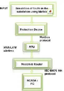
Available Online at www.ijpret.com 489 In this project the major focus is on the station and bay level. The fault is injected at bay level and observed at station level. The issues during configuration and sending the data from the devices to SCADA via wired and wireless communication are highlighted. The communication protocol of devices with RTU is using Modbus and that of RTU to SCADA is IEC60870 104.
Fig 2 Architecture of the setup
o Simulation of Faults in Matlab
An abnormal condition occurring on the transmission line that deviates the current and voltage from its normal value is known as a fault. Electrical faults are basically of two types: Symmetrical and unsymmetrical. Symmetrical faults are 3 phase faults while asymmetrical are Single line to ground, Double line to ground and line to line fault.
Fig 3: Simulation Model of Faults
Available Online at www.ijpret.com 490
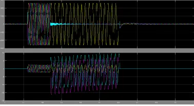
Fig 4: Voltage and Current Waveform for Single Line to ground Fault
Fig 5: Voltage and Current Waveform for Double Line to ground Fault
The circuit breaker is closed at 0.12s and the fault is injected at 0.24s.From 0.12s till 0.24s the voltages are found normal however after 0.24s the voltage of phase A drops down to 0 and the current shoots up. The fault is cleared and breaker is opened at 0.6s. In case of Double line to ground faults, the faults currents in 2 phases shoot up while for 3 phase faults all the three phase currents shoot up.
These faults are injected to protection device (condition monitoring device) by converting Matlab files to COMTRADE (Common Format for Transient Data Exchange) format as below.
Data (.dat) file—Mandatory binary or ASCII text file. A data file contains a time-stamped numerical value for each input channel for each sample in the record. Values can be zero-based or have a zero offset.
Configuration (.cfg) file—Mandatory ASCII text file. A configuration file contains information to interpret the data file such as
the sampling rates, number of channels, line frequency, and channel information.
Available Online at www.ijpret.com 491 Source: 11KV, Transformer: 11KV/3.3KV, 14 KVA, Load: 10KW, 100VAR
The KVA rating was calculated using equation (1).
KVA=(1.732*V*I ) /1000 (1)
Integration of Protection Devices to SCADA
The set up consists of an integration of condition monitor and RTU to SCADA using GPRS modem and M2M gateway. A remote terminal unit (RTU) is a microprocessor controlled electronic device that interfaces objects in the physical world to a Distributed control system or SCADA system by transmitting telemetry data to a master system, and by using messages from the master supervisory system to control connected objects. An RTU monitors the field digital and analog parameters and transmits data to the Central Monitoring Station. It contains setup software to connect data input streams to data output streams, define communication protocols, and troubleshoot installation problems [3].
o Communication protocols
The MODBUS protocol follows a client/server (master/slave) architecture where a client will request data from the server (Ref Fig7). The client can also ask the server to perform some action. The client initiates a process by sending a function code that represents the type of transaction to perform. The transaction performed by the MODBUS protocol defines the process a controller uses to request access to another device, how it will respond to requests from other devices, and how errors will be detected and reported. The MODBUS protocol establishes a common format for the layout and contents of message fields. Controllers communicate using a master/slave technique where only one device, the master, can initiate transactions or queries. The other devices, slaves, respond by supplying the requested data to the master or by taking the action requested in the query.
Available Online at www.ijpret.com 492
Fig 6: Modbus Frame
MODBUS transactions always perform a set of actions by reading or writing to a set of four data types. Table 1 describes the four data formats used by the MODBUS application layer
Table 1: Modbus Data types
Fig 7: Complete Modbus transaction
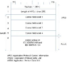
IEC 60870-5-104 (also known as IEC 870-5-104) is an international standard, released in 2000 by the IEC(International Electrotechnical Commission). IEC 60870-5-104 enables communication between control station and substation via a standard TCP/IP network. The biggest advantage of IEC 60870-5-104 is that it enables communication via a standard network, which allows simultaneous data transmission between several devices and services. It supports single point, double point and Regulating commands. It consists of the following telegram format.
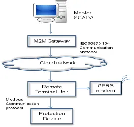
Available Online at www.ijpret.com 493 o SCADA Configuration with RTU using wireless communication
Fig 9: RTU, SCADA Integration using wireless communication
In this setup (Ref Fig9), RTU communicates with the protection device using Modbus communication protocol at the data layer. As Modbus supports master –slave communication there is continuous polling of data. At the higher level i.e. Network layer, IEC 60870 104 enables communication between control station (SCADA) and substation (RTU) via a standard TCP/IP network. The communication between the substation and the Control station is wireless through GPRS.GPRS architecture works on the same procedure like GSM network, but, has additional entities that allow packet data transmission [4]. This data network overlaps a second-generation GSM network providing packet data transport at the rates from 9.6 to 171 kbps. Along with the packet data transport the GSM network accommodates multiple users to share the same air interface resources concurrently.
o SCADA Configuration with FRTU using wired communication
Fig 10: RTU SCADA Integration using wired Communication
Available Online at www.ijpret.com 494 o CONCLUSION
The fault indication from the protection device to SCADA was observed. Along with the fault indications voltages and currents were also monitored on SCADA in both the cases wired and wireless communication. There are various factors that impact the wired and wireless communication. Cost Reduction is an important factor in wireless communication using GPRS. In this set up the cost is dependent on the data packets of the communication sent and not on the connection time. Also the advantage of authentication is available to secure the connection. Moreover signal sharing is enabled thus allowing more than one person to communicate with another network source at any one time. In case of bad weather the connections are lost frequently, however due to the capability of 104 protocol of connection retries, the connection can be regained in less time. However there are factors that affect the wireless communications. The delay in the data transfer is observed in case of wireless (due to the time required to communicate from GPRS modem to the M2M Gateway). Positioning of the Antenna and obstacles in the signal path (buildings, walls) are the other factors impacting the performance of wireless communication. Wired communications are often faster and have better throughput compared to wireless. It is more secured and reliable however the setup cost and time required is more. Also it is found to be less flexible and limited to some types of buildings only. As per the analysis done, it is found that the communication done using wired and wireless system has its own advantages and disadvantages. The data transfer has to be continuous and faster so that Fault Localization and Restoration takes place faster. It would depend on the requirement of the customer to choose the right technology as the data transmitted is very crucial for smooth supply of electricity.
REFERENCE:
1. DISTRIBUTION AUTOMATION SOLUTIONS – IMPACT ON SYSTEM AVAILABILITY IN DISTRIBUTION NETWORKS, 21st International Conference on Electricity Distribution, Oliver SCHROEDEL ,Siemens AG – Germany oliver.schroedel@ siemens.com, Michael SCHWAN Siemens AG – Germany michael.schwan@ siemens.com, Sven KOEPPE Siemens AG – Germany sven.koeppe@ siemens.com, Robert ROSENBERGER .
2. www.siemens.com/energy-automation www.siemens.com/smart-grid.