Available Online at www.ijpret.com 300
INTERNATIONAL JOURNAL OF PURE AND
APPLIED RESEARCH IN ENGINEERING AND
TECHNOLOGY
A PATH FOR HORIZING YOUR INNOVATIVE WORK
MODELING, SIMULATION AND DYNAMIC ANALYSIS OF TRICEPT PARALLEL
MANIPULATOR
S. KARTHICK1, M. SEENIVASAKUMAR2 Assistant Professor, Apollo Engineering College, Chennai, Tamilnadu, India.
Accepted Date: 22/11/2014; Published Date: 01/12/2014
\
Abstract: The science and technology of robotics originated with the spirit of developing mechanical systems which would carry out tasks normally ascribed to human beings. Parallel manipulator has low workspace compared to serial manipulator. In previous research works, the workspace was maximized by reducing the number of connecting legs or limbs between the moving platform and fixed platform. As the numbers of legs are reduced, the stability of the manipulator reduces. To compromise the problem Tricept parallel manipulator had been discovered. In this project work by changing the design parameters of Tricept parallel manipulator, the characteristics of Tricept parallel manipulator were verified. The modeling is done in Solid works Software. A prototype model will be fabricated. The best selected model is simulated using ADAMS software. The dynamic analysis will be done using ADAMS software. The Tricept parallel manipulator will be fabricated. An experiment will be conducted using the fabricated model and the results will be tabulated.
Keywords: Tricept parallel manipulator, Solid works, ADAMS.
Corresponding Author: MR. S. KARTHICK
Access Online On:
www.ijpret.com
How to Cite This Article:
S Karthick, IJPRET, 2014; Volume 3 (4): 300-308
Available Online at www.ijpret.com 301
INTRODUCTION
The science and technology of robotics originated with the spirit of developing mechanical systems which would carry out tasks normally ascribed to human beings. It is quite natural that the main thrust was towards using open-loop serial chains as robot manipulator. Such manipulators have the advantage of sweeping workspaces and dexterous maneuverability like the human arm, but their load carrying capacity is rather poor due to cantilever structure. Consequently, the links tends to bend at high load on the one hand, while on the other, to satisfy the strength requirements the links become bulky which leads to Vibration at high speed. Though possessing a large workspace, their precision positioning capability is poor. Hence for applications where high load carrying capacity, good dynamic performance and precise positioning are of paramount importance, it is desirable to have an alternative to conventional serial manipulators. For possible solutions one can look into the biological world and observe that
1. The bodies of load carrying animals are more stably supported on multiple in parallel legs compared to the biped human.
2. Human beings also use both the arms in co-operation to handle heavy loads.
3. For precise work like writing three fingers actuated in parallel are used.
In general, it can be accepted that robot manipulators having the end effector connected to the ground via several chains having actuation in parallel will have greater rigidity and superior positioning capability. Thus makes the parallel manipulators attractive for certain applications and the last two decades have witnessed considerable research interest in this direction. Industrial robots play a central role in factory automation. However, there has been little effort as to the application of application of robots in machining work such as grinding, cutting, milling, drilling etc. This kind of work requires robot manipulators to have high stiffness, rigidity and accuracy which cannot be provided by conventional serial robot manipulators. Hence for the application like these it is desirable to have parallel manipulators.
1.1Definition of Parallel Manipulator
Available Online at www.ijpret.com 302
actuators can be mounted at or near the fixed base. For this reason parallel manipulators are sometimes called as platform manipulators. In parallel manipulators, the external load is shared by the actuator, it tends to have a large load carrying capacity. A parallel manipulator is said to be symmetrical if it satisfies the following conditions
1. The number of limbs is equal to the number of degrees of freedom of the moving platform.
2. The type and number of joints in all the limbs are arranged in an identical pattern.
3. The number and location of actuated joints in all the limbs are the same.
1.2Tricept Parallel Manipulator
The Tricept parallel manipulator has four supporting limbs that meet at four distinct points both in the fixed base and the moving platform. Three of he four limbs called the SPS limbs, share the same kinematic structure. The SPS limb connects the fixed base to the moving platform by a spherical joint followed by a prismatic joint and spherical joint. Each prismatic joint is driven by a linear actuator. If we neglect the passive degree of freedom about the line passing through the two spherical joints, the total joint degree of freedom or the connectivity of each SPS limb is equal to six. Hence, these SPS limbs do not impose any constraint on the moving platform. The fourth leg, called an UP leg, connects the fixed base to the moving platform by a universal joint followed by a prismatic joint. The connectivity of an UP leg is equal to three. Therefore, it provides three constraints on the moving platform. We refer UP limb as a passive leg since it is not driven by any actuator. The Tricept parallel manipulator is mainly used in positioning device [6].
1.3Description Of The Mechanism
Available Online at www.ijpret.com 303
2. MODELING OF TRICEPT PARALLEL MANIPULATOR USING SOLIDWORKS SOFTWARE
Solidworks is a commercial CAD/CAM package that is widely used in industry for CAD/CAM applications. It is one of the new generations of system that not only offer a full 3-D solid modeler, n in contrast to purely 2-D and surface modelers, but also parametric functionality and full associability. This means that explicit relationships can be established between design variables and changes can be made at any point in the modeling process and the whole model is updated. The method of constructing a model of an object is very similar to that followed in the production of a physical component
3. DESIGNED MODELS IN SOLIDWORKS SOFTWARE
The different types of models of Tricept parallel manipulators are Revolute joint and spherical joint(RS)-Configuration, Revolute joint and Revolute joint(RR)-Configuration, Revolute joint and
Universal joint(RU) –Configuration, Spherical joint and Spherical joint (SS) –Configuration, Universal joint and Revolute joint(UR) –Configuration, Universal joint and spherical joint(US) –
Configuration, Universal joint and Universal joint(UU) -Configuration
3.1 RS-Configuration
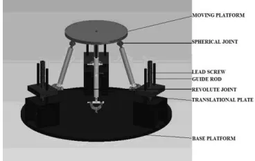
The mechanism of Figure.3.1 consists of a base platform, three inextensible links, one prismatic link, three revolute joint, three spherical joint and a moving platform. Links are connected to the moving platform by means of spherical joints at one end and other end to half nuts by means of revolute joints. The half nuts are mounted on the lead screws, which are coupled to the stepper motor and all are placed perpendicular to the base platform. A prismatic link is connected to midpoint of the moving platform by revolute joint at one end and other end to midpoint of the base platform by means of universal joint.
Available Online at www.ijpret.com 304
4. PROTOTYPE MODEL OF TRICEPT PARALLEL
MANIPULATOR
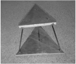
The prototype model has been fabricated using two triangular wood boards and four prismatic links. The Tricept parallel manipulator prototype model has four supporting limbs that meet at four distinct points both in the fixed base and the moving platform. Three of the four limbs connected at the corner of the triangular board between moving platform and base platform. Each prismatic link can be actuated manually. Fourth prismatic link is connected to midpoint of the moving platform perpendicular to midpoint of the base platform.
Figure 4.1 BEFORE ACTUATION
5. SIMULATION OF TRICEPT PARALLEL MANIPULATOR USING ADAMS SOFTWARE
ADAMS (Automatic Dynamic Analysis of Mechanical Systems) was developed by MDI (Mechanical Dynamics Inc). It is the MDI’s powerful modeling and simulating environment, which helps to solve the design problems. We can use ADAMS/view to built, simulate and define virtual models of mechanical systems that has moving parts. There are two types of interfaces that one can access the ADAMS products, product menu and the program menu. ADAMS/View can be used for creating and simulating the model of any mechanical systems. One can test the model in the same environments that actual product will experience in real time applications. ADAMS/Solver is MDI’s powerful analysis environment that automatically solves the equations of motion for kinematics, static, quasistatic or dynamic simulations.
Available Online at www.ijpret.com 305
Table 5.1 Results of Position Analysis
5.2 SIMULATED MODEL IN ADAMS SOFTWARE
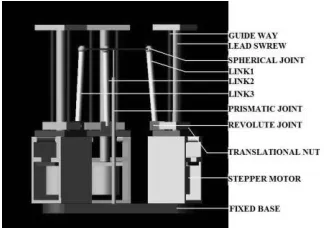
The Revolute Joint and Spherical Joint configuration model of Tricept parallel manipulator is selected as best model for simulation and fabrication. The model has been selected based on position analysis results. Figure 5.1 shows the front view of the Tricept parallel manipulator. The mechanism consists of a base platform, three inextensible links, one prismatic link, three revolute joint, three spherical joint and a moving platform. Links are connected to the moving platform by means of spherical joints at one end and other end to half nuts by means of revolute joints. The half nuts are mounted on the lead screws, which are coupled to the stepper motor and all are placed perpendicular to the base platform. A prismatic link is connected to midpoint of the moving platform by revolute joint at one end and other end to midpoint of the base platform by means of universal joint.
Figure 5.1 Front View of Tricept
Parallel Manipulator in ADAMS
Available Online at www.ijpret.com 306
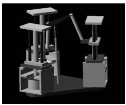
In Figure 5.3 shows the image when link1 and link2 is actuated. The link1 and link2 is actuated simultaneously by means of stepper motor. As stepper motor 1&2 rotates, the nut 1&2 is translated in Z direction, so link1 and link2 is actuated and moving platform is rotated about the axis in Y direction. Link3 is not actuated at this state of position.
Figure 5.2 Simulated View-Single
LIMB ACTUATED
Figure 5.3 Simulated View Two limbs actuated Figure 5.4 Simulated View -Three limbs actuated
In Figure 5.4 shows the image when link1, link2 and link3 is actuated. The link1, link2 and link3 are actuated simultaneously by means of stepper motor. As stepper motor 1, 2&3 rotates, the nut 1, 2&3 is translated in Z direction, so link1, link2 and link3 is actuated and moving platform is translated about the axis in Z direction.
6. DYNAMIC ANALYSIS
Dynamics deals with the mathematical formulations of the equations of the robot arm motion. The dynamic equations of the motion of the manipulator are a set of mathematical equations describing the dynamic behavior of the manipulator. Such equations of motion are useful for computer simulation of the robot arm motion.
Available Online at www.ijpret.com 307
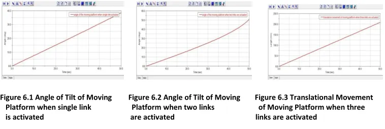
In figure 6.2, when two links are activated, Moving platform is tilted to an angle to 52º for translational movement of the Nut.
In figure 6.3, when three links are activated, Moving platform is translated to a distance of 210 mm in Z-axis for translational movement of the Nut.
Figure 6.1 Angle of Tilt of Moving Figure 6.2 Angle of Tilt of Moving Figure 6.3 Translational Movement Platform when single link Platform when two links of Moving Platform when three is activated are activated links are activated
7. CONCLUSION
The different types of models of Tricept parallel manipulator have been created using Solid works Software. A prototype model of Tricept parallel manipulator has been fabricated. Familiarization of Solid works and ADAMS software has been done and the model of Tricept parallel manipulator has been created in ADAMS Software and the model has been simulated in ADAMS Software. The dynamic analysis has been performed and the results are tabulated. Fabrication of the Tricept parallel manipulator will be done. The experimental analysis is to be performed on the fabricated model.
8. REFERENCES
1. Alexei Sokolov and Paul Xirouchakis (2006) “Dynamics analysis of a 3- DOF parallel manipulator with R–P–S joint structure”, Mechanism and Machine Theory. pp.541-557.
2. Feng Gao , Weimin , Hui Zhao , Xianchao Zhao and Zhenlin Jin New (2002) “Kinematic Structures for 2-, 3-, 4-, and 5-DOF Parallel Manipulator Designs” Mechanism and Machine Theory, pp1395-1411.
3. Geoffrey Pond and Juan A Carretero (2006) “Quantitative dexterous workspace comparison of parallel manipulators” Mechanism and Machine Theory, pp.1388-1400.
Available Online at www.ijpret.com 308
5. Lung-wen Tsai and Sameer Joshi (2003) “A Comparison Study of Two 3-DOF parallel manipulators: One with Three and the other with Four Supporting legs”, IEEE Transactions on Robotics and Automation, Vol.19. No.2. pp.200-209.