CFD Analysis & Optimization of Fuel Injector by
Changing its Geometry
Chirag J. Padhya Ashish R. Patel
PG student (I.C./Auto) Assistant Professor
Department of Mechanical Engineering Department of Mechanical Engineering
Merchant Institute of Technology, Pilludara Merchant Institute of Technology, Pilludara
Abstract
A proper and synchronized fuel injection is paramount for a good engine performance, since it provides a homogeneous combustion among the cylinders. The use of alternative fuels such as Ethanol, Methanol and Natural Gas in automotive applications has increased due to the strict environmental regulations. These are used to reduce automotive emissions, especially in heavy trucks and city bus fleets. Most of these vehicles use diesel fuel as their primary fuel. Trucks and buses with Detroit Diesel engines have the option to operate using methanol as their primary fuel instead of diesel fuel.Due to the low lubricity of methanol fuel, the unit fuel injectors injecting methanol fuel have a shorter operating life than those injecting diesel fuel do.Using the computational fluid dynamics programs CFX and CFX obtained the pressure and velocity profiles for pre-selected locations in the fluid path of the injector. Locations of high and low velocity areas were determined to be performance inhibitors and possible failure points and Find the way to minimize failure points.
Keywords: Fuel Injector, Emission control, Fuel Flow Penetration, Nozzle Diameter, Nozzle geometry, Back Pressure, Cone Angle, Transient Fuel Spray Formation, optimization
_______________________________________________________________________________________________________
I.
I
NTRODUCTIONEffect of injector nozzle geometry and operating pressure condition such as opening pressure, ambient pressure, and injection pressure on the transient fuel spray behavior have been examined by experiment. In order to clarify the effect of internal flow inside nozzle on the external spray, flow details inside model nozzle and real nozzle were also investigated both experimentally and numerically. For the effect of injection pressure, droplet sizes and velocities were obtained at maximum line pressure of 21 MPa and 105 MPa.A modern compression ignition engine should meet ecological and economical requirements
.
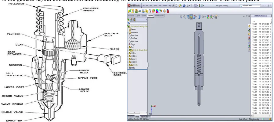
It should have high performance-fuel consumption ratio, low maintenance costs and it should be enable operation under prescribed emission regulations. As the process of combustion and further the production of pollutants and noise emissions is mainly controlled by the process of fuel injection, a lot of effort is put into the development of new and improvement of existing diesel fuel injection systems. The cavitating flow in diesel injector nozzles has been extensively investigated by a number of researchers due to its strong impacts on the fuel spray atomization and consequent spray combustion in Diesel Engines. From an early study about cavitating flow in small nozzles and stated that cavitations creates large amplitude of disturbance which results in enhancing jet atomization and examined cavitations in various nozzles with different geometries.Below is the general layout construction and modelling of common fuel injector in Solid works with its all parts.
II.
E
XPERIMENT DATAFig. 2.1 Injector Drawing sheet for EV14s
Initial Data for test: A.
Table – 1 Initial Data for test:
Sr. No. Factors Values
1. System Pressure Max. 8 bar
2. Weight Max. 30 bar
3. Installation Length 33.6/48.65/60.65 mm
4. Fuel Input Top Feed Injector
5. Operating Temp. -
6. Permissible Fuel Temp.
7. Spray Type Conical Or E(2-spray)
8. Flow rate at 3 Bar 146 to 146.2 cm3/min
9. Spray Angle
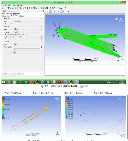
Fig. 3.2 Domain and Material of the Injector
Fig. 3.3 Velocity generated at ZX plane & at outlet in the Injector
IV.
R
ESULT&
COMPARISONExisting Geometrical parameters A.
Nozzle Diameter: 0.145 mm No. of Holes in Nozzle: 6 Clearance: 0.5 mm
Result of standard model from test report: B.
Pressure at outlet: 18.1 bar Velocity at outlet: 152.15 m/s
CFD analysis result: C.
Pressure at outlet: 20.449 bar Velocity at outlet: 151.509 m/s
Variation: D.
In pressure: 0.99% In velocity: 1.107%
V.
M
ETHODOLOGYTaguchi Method A.
A scientific approach to plan the experiments is a necessity for efficient conduct of experiments. By the statistical design of experiments the process of planning the experiment is carried out, so that appropriate data will be collected and analysed by statistical methods resulting in valid and objective conclusions. When the problem involves data that are subjected to experimental error, statistical methodology is the only objective approach to analysis. Thus, there are two aspects of an experimental problem: the design of the experiments and the statistical analysis of the data. These two points are closely related since the method of analysis depends directly on the design of experiments employed.
Selection of Process Parameters 1)
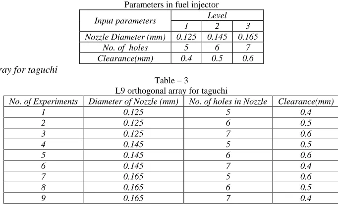
The three parameters in fuel injector can be consider which are Nozzle diameter, No. of holes in Nozzle, annular clearance. Table – 2
Parameters in fuel injector
Input parameters Level
1 2 3
Nozzle Diameter (mm) 0.125 0.145 0.165
No. of holes 5 6 7
Clearance(mm) 0.4 0.5 0.6
L9 orthogonal array for taguchi 2)
Table – 3
L9 orthogonal array for taguchi
No. of Experiments Diameter of Nozzle (mm) No. of holes in Nozzle Clearance(mm)
1 0.125 5 0.4
2 0.125 6 0.5
3 0.125 7 0.6
4 0.145 5 0.5
5 0.145 6 0.6
6 0.145 7 0.4
7 0.165 5 0.6
8 0.165 6 0.5
Result generated by using DOE and Anova analysis: B.
Fig. 4: DOE and Anova analysis
VI.
C
ONCLUSION As per review of research papers, we can see that during all circumstances and combustion process there will be major output change with changing the several parameters likewise plunger spring tension, nozzle diameter, angle of attack (cone angle), tip formation, number of holes of injector, intensity of pressure, stoichiometric level of mixture etc will increase the combustion efficiency and reduce the level of NOx emission gases.
From DOE analysis the maximum mean effect of parameter is no. of holes of nozzle but for more accurate result the Anova analysis is to be done.
From Anova analysis the factor level prediction is Nozzle dia. 125 mm, No. of holes 5, and annular clearance 0.4 mm. This design is the optimized design which gives the more effective output efficiency than standard model.
R
EFERENCES[1] Ja ye koo “The Effect Of Fuel Injector Nozzle Geometry and Operating Pressure Condition On Transient Fuel Spray Behavior”, School Of Aerospace and Mechanical Engg. Hankuk Aviation University, Kyunggi-do 412-791, Korea, KSME International Journal, Vol. 17 No. 3, PP 617-625, 2003.
[2] Martin Volmajer, Breda Kegl “Experimental And Numerical Analysis Of Fuel Flow In The Diesel Engine Injection Nozzle”, University of Maribor, Faculty of mechanical engineering, Smetanova 17, S/-2000 Marihor, Slovenia, Journal of Kones. Combustion Engines, VoI. B, No 1-2,2001.
[3] R. Payri , F.J. Salvador, J. Gimeno, L.D. Zapata, “Diesel nozzle geometry influence on spray liquid-phase fuel penetration in evaporative conditions”, CMT-Motores Te´rmicos, Universidad Polite´cnica de Valencia, Camino de Vera s/n, E-46022, Spain, Science Direct, Fuel 87(2008)1165-1176.
[4] N. Mitroglou, C. Arcoumanis, K. Mori1 “Mixture distribution in a multi-valve twin-spark ignition engine equipped with high-pressure multi-hole injectors”, Y. Motoyama1 Centre for Energy and the Environment, School of Engineering and Mathematical Sciences, City University, London 1Yamaha Motor Company, Japan, Journal of Physics: Conference Series 45 (2006) 46–58.