_____________________________________________________________________________________________________ *Corresponding author: Email: [email protected];
Numerical Study of Strip Footings Behavior on
Compacted Sand
Nasser A. A. Radwan
1*and Khaled M. M. Bahloul
21
Housing and Building National Research Center, Cairo, Egypt.
2Department of Construction Engineering, October High Institute of Engineering and Technology,
Egypt.
Authors’ contributions
This work was carried out in collaboration among two authors. Author NAAR designed the study, managed the analysis of the study, wrote the protocol and wrote the first draft of the manuscript. Author KMMB performed the analyses of the study and the literature searches. Both authors read and approved the final manuscript.
Article Information
DOI: 10.9734/JERR/2019/v5i316924 Editor(s): (1) Dr. Okan Özer, Professor, Department of Engineering Physics, Engineering Faculty, University of Gaziantep, Turkey. Reviewers: (1) Guettouche Amar, Ferhat Abbas University of Setif, Algeria. (2)Jitesh T. Chavda, Indian Institute of Technology Madras, India. (3)Xuguang Chen, Ocean University of China, China. Complete Peer review History:http://www.sdiarticle3.com/review-history/49135
Received 10 March 2019 Accepted 19 May 2019 Published 24 May 2019
ABSTRACT
The aim of this research is to investigate numerically the effect of using compacted sand as soil replacement layer beneath a strip footing on its bearing capacity. Finite element computer software Plaxis 2D version 8.6 was used to predict the behavior of strip footing resting on loose sand and on compacted sand. Study was conducted for footing widths of 1 up to 2 meters and various depths ranging from 1m up to 2m, also the effect of replacement layer thickness was investigated. It was found that using replacement layer beneath strip footing increases its bearing capacity for different widths and depths of footing. This improvement is observed up to thickness of replacement layer equal to 3 times the footing width (H/B=3), where further increase in replacement layer thickness does not affect significantly bearing capacity of footings.
Keywords: Strip footing; compacted sand; bearing capacity; finite element; plaxis.
1. INTRODUCTION AND PREVIOUS RESEARCH
The main objective of this research is to study the effect of compacted sand layer beneath strip footing on ultimate bearing capacity because in many practical engineering cases, shallow foundations may rest on multilayered soil system. A layer of soil beneath shallow foundation which influences the bearing capacity is called a subsoil. A simplified analysis shows that the thickness of the subsoil can be expressed by:
H = tan (45 + )
Where B is a width of a shallow foundation, and is the angle of soil internal friction [1]. In the engineering practice, it is usually assumed that H = 2B. therefore, subsoil is considered a multi layered system if the thickness of the soil surface layer is less than H. Two types of surface layer have been recognized, firstly Surface layer weaker than lower layer and secondly, Surface layer stronger than lower layer as the case in current study.
Research on the ultimate bearing capacity problems can be carried out using analytical solutions, experimental investigations and numerical model using finite element analysis. A satisfactory solution is found only when theoretical results agree with those obtained experimentally and numerically. For layered soil profile as the case in this research (compacted sand underlined by loose sand). The ultimate load failure surface in the soil depends on the shear strength parameters of the soil layers such as; the thickness of the upper layer; the shape, size and embedment of footing; and the ratio of the thickness of the upper layer to the width of the footing.
Over the last few decades, many research deals with the problem of foundations resting on layered soils. At first, researchers based their studies on the results of prototype laboratory model testing in order to develop empirical formulae to predict the ultimate bearing capacity of these footings. Recently, theories based on finite element analyses were presented and gave more accurate solutions as compared to the previous ones. Previous research includes work done by:
Hanna [2] studied experimentally the case of footings resting on subsoil consisting of a strong
sand layer overlying a weak sand deposit. His theory is that at ultimate load, a soil mass of the upper layer is pushed to the lower sand layer, and by calculating the forces on the assumed vertical punching failure surface, the ultimate bearing capacity can be calculated theoretically. He conducts model tests on strip and circular footings resting on dense sand layer overlying loose sand layer, to verify his theory and the results of the tests agreed well with the theory presented. This method has been used as a solution of bearing capacity improvement of loose sand layer immediately beneath footing by replacing it by a stronger layer.
Georgiadis and Michalopoulos [3], presented a numerical method for evaluating the bearing capacity of shallow foundations on layered soil, which may contain any combination of cohesive and non-cohesive layers. Several potential failure surfaces were analyzed. Comparisons between the results obtained with this method, a number of semi-empirical solutions for homogeneous and two-layer soil profiles, experiments and other numerical methods including finite elements, demonstrated the validity of the proposed method.
Burd and Frydman [4], presented the case of bearing capacity of a rigid plane-strain footing placed on the surface of a soil consisting of a uniform sand layer overlying thick, homogeneous bed of clay. The research is restricted to cases where the thickness of the sand layer is comparable to the footing width, they assumed that the clay layer is considered undrained, and the sand layer is drained.
A parametric study has been carried out using two distinct numerical modeling. First, finite element method using OXFEM software. And secondly, the finite difference calculations were performed using FLAC software. The results of the study have been used to produce charts of bearing capacity that may be used directly in design.
Application of load spreading method known as projected area method has been studied by some researchers for two-layered soil system [5,6,7]. In this approach, external load is supposed to spread linearly from either edge of footing to a larger area of sand as pressure penetrates deeply into the top layer through a constant angle therefore the intensity of the load decreases along the depth.
Anitha and Niranjana [8], conduct a numerical study on bearing capacity of strip footing on multilayered soil system using Plaxis 3d software. They studied the effect of embedment and effect of top layer thickness on the ultimate bearing capacity of strip footing in two layered soil system with and without geotextile at the interface. It was found that the bearing capacity increases and the settlement of footing decreases, as the thickness of top layer increases to an optimum value beyond which there is no substantial increase in bearing capacity. This optimum thickness is H/B=3 in case of layered soil without geotextiles, while in case of using geotextile this optimum thickness decreases to H/B=2.
Chavda and Dodagoudar [9], they conduct a numerical study of ultimate bearing capacity of strip footings using using various constitutive models and sensitivity analysis. The software used was Plaxis 2d ver. 2016. The material models used are Mohr–Coulomb (MC) model, Hardening Soil (HS) model Hardening Soil model with small-strain stiffness (HSsmall), and Soft Soil (SS) model. It was found from the results of FE analysis that the ultimate bearing capacity of strip footings depends on the shear strength parameters, width of footing, unit weight of soil, and surcharge at the base level of the footing. It was found also, that the ultimate bearing capacity value is about the same for all mentioned material models. The FE results are compared with the analytical solutions of Terzaghi and Meyerhof.
2. MATERIALS AND METHODS
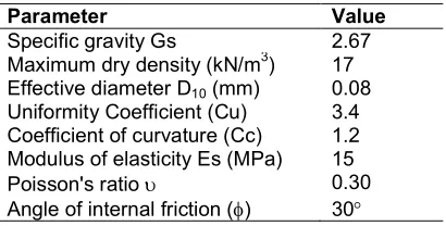
The material used in this study is fine to medium sand. Sand is classified as SP according to Unified Classification System. The properties of sand sample are given in Table 1.
2.1 Numerical Analysis
Numerical analysis using the finite element method (FEM) was carried out using finite
element method computer software (PLAXIS ver. 8.6) to study the behavior of strip footing resting on loose sand and on compacted sand. The PLAXIS Version 8.6 is used for the two-dimensional analysis of deformation and stability in geotechnical engineering. Full modelling of soil, footing and loading are performed.
Table 1. Summary of sand properties
Parameter Value
Specific gravity Gs 2.67
Maximum dry density (kN/m3) 17 Effective diameter D10 (mm) 0.08
Uniformity Coefficient (Cu) 3.4 Coefficient of curvature (Cc) 1.2 Modulus of elasticity Es (MPa) 15
Poisson's ratio 0.30
Angle of internal friction () 30
2.2 Numerical Model Setup
The soil was modeled using an elasto - plastic type of hyperbolic model, called the hardening soil model. The hardening soil model implemented in PLAXIS combines of plasticity theory with the logic of the Duncan-Chang model. It involves ten input parameters, including cohesion (effective) C, angle of internal friction (effective) , angle of dilatancy , primary loading stiffness E50ref, primary oedometer
loading stiffness Eoed ref, unloading-reloading
Poisson's ratio ur, unloading- reloading stiffness
Eurref, power m in stiffness laws and failure ratio Rf. The soil parameters used in plaxis software
are shown in Table 2.
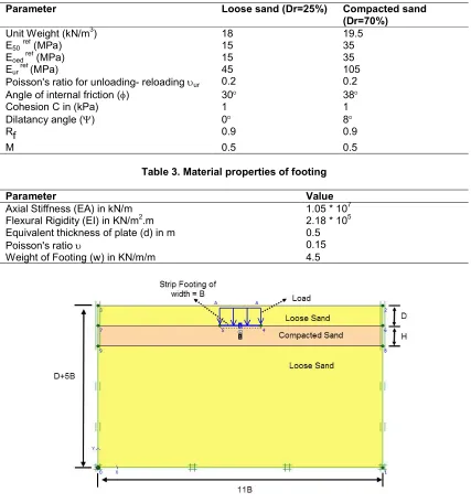
The footing was modeled as a rigid plate element having properties as shown in Table 3. A strip footing of widths ranging from 1m up to 2 m was placed at depths ranges from 1 m up to 2 m below soil surface at the center of the soil model as shown in Fig. 1 The finite element model used the 6-noded triangular elements. According to Ronald and Wendy [10], the coarseness of the finite element mesh plays an important role regarding accuracy of finite element model results where, FE method gives an upper bound (unsafe) solution for bearing capacity problems in case of using coarse mesh. Upon mesh refinement the bearing capacity reduces towards its theoretical value. therefore, Medium mesh size was used with refinement cluster beneath the footing.
boundary as shown in Fig. 1. To verify the improvement of bearing capacity a single layer of loose sand beneath the footing was considered first, then a compacted sand layer beneath the footing was used with varied
thicknesses from 0.5 m up to 3.5 m to verify the effect of compacted layer on bearing capacity
of footing. The effect of footing width and depth on bearing capacity was investigated also in case of loose sand layer and for compacted layer.
Figs. 2-5 show the deformed mesh of the model and total displacement contours after application of footing load in case of Strip footing of width = 1m and at depth equal to 1m resting on loose sand and compacted sand layer of thickness equal to 1 m.
Figs. 6-7 show the mean stress distribution in case of Strip footing at depth equal to 1m resting on loose and compacted sand layer of thickness equal to 1 m.
Table 2. Soil parameters
Parameter Loose sand (Dr=25%) Compacted sand (Dr=70%)
Unit Weight (kN/m3) 18 19.5
E50ref (MPa) 15 35
Eoed ref (MPa) 15 35
Eur ref (MPa) 45 105
Poisson's ratio for unloading- reloading ur 0.2 0.2
Angle of internal friction () 30 38
Cohesion C in (kPa) 1 1
Dilatancy angle () 0 8
Rf 0.9 0.9
M 0.5 0.5
Table 3. Material properties of footing
Parameter Value
Axial Stiffness (EA) in kN/m 1.05 * 107
Flexural Rigidity (EI) in KN/m2.m 2.18 * 105
Equivalent thickness of plate (d) in m 0.5
Poisson's ratio 0.15
Weight of Footing (w) in KN/m/m 4.5
Fig. 2. Deformed mesh for loose sand Fig. 3. Deformed mesh for compacted sand layer
Fig. 4. Total displacement contours for loose sand
Fig. 5. Total displacement contours for compacted sand layer
Fig. 6. Mean effective stress distribution under the footing resting over loose sand
Fig. 7. Mean effective stress distribution under the footing resting on compacted
sand
Fig. 9. Comparison between analytical vs finite element method results in case of 1 m width strip footing resting on compacted sand layer
2.3 Comparison between Finite Element
Method and Analytical Solution
Results
An analytical study was performed to verify the accuracy of Numerical study carried out using Plaxis software. As shown in Figs. (8-9) for cases of strip footing resting on loose sand and compacted sand layers. It was observed that a good agreement was obtained by comparing the FEM results with results obtained by analytical solutions [11-12] for determining ultimate bearing capacity of strip footings therefore, FEM using Plaxis software is capable of predicting ultimate bearing capacity for both cases.
3. RESULTS AND DISCUSSION
The behavior of strip footing resting on loose sand and compacted sand layer is shown as the relationship between applied stress versus settlement. Table 4 illustrate the parametric study
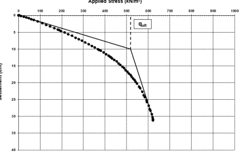
results of ultimate bearing capacity values obtained by FEM in case of footing resting on loose sand for different depths and widths. The values of ultimate bearing capacity are obtained using tangent intersection method [13] as shown in Fig. 10.
3.1 Effect of Footing Embedment Depth
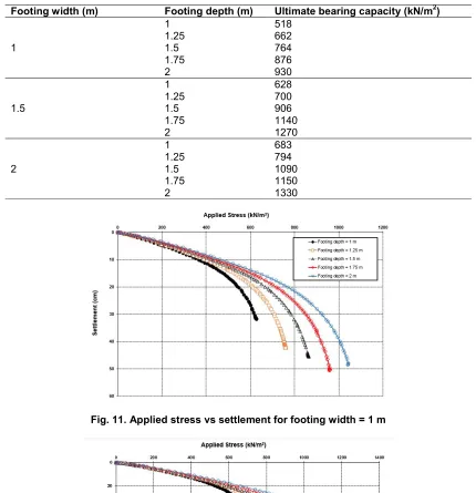
To study the effect of footing embedment depth on ultimate bearing capacity the relationship between applied stress versus settlement at various depths for footing resting on loose sand for various widths are studied as shown in Figs. (11-13) the relationship between applied stress versus settlement for various footing widths and depths. it was observed that the ultimate bearing capacity improved significantly with the increase of footing embedment depth associated with a corresponding reduction in settlement for the same stress values.
Table 4. Ultimate bearing capacity values for different cases
Footing width (m) Footing depth (m) Ultimate bearing capacity (kN/m2)
1
1 518
1.25 662
1.5 764
1.75 876
2 930
1.5
1 628
1.25 700
1.5 906
1.75 1140
2 1270
2
1 683
1.25 794
1.5 1090
1.75 1150
2 1330
Fig. 11. Applied stress vs settlement for footing width = 1 m
Fig. 13. Applied stress vs settlement for footing width = 2 m
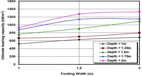
3.2 Effect of Footing Width
To study the effect of footing width on ultimate bearing capacity the relationship between
ultimate bearing capacity and footing width at various depths was plotted as shown in Fig.
14. From Fig. 14 it was observed that the ultimate bearing capacity increases with
increase of footing width. The maximum percentage improvement of ultimate bearing
capacity obtained was 43% for footing depth equal to 2m, therefore, it was concluded
that the effect of footing width is more pronounced for footings with bigger embedment depth.
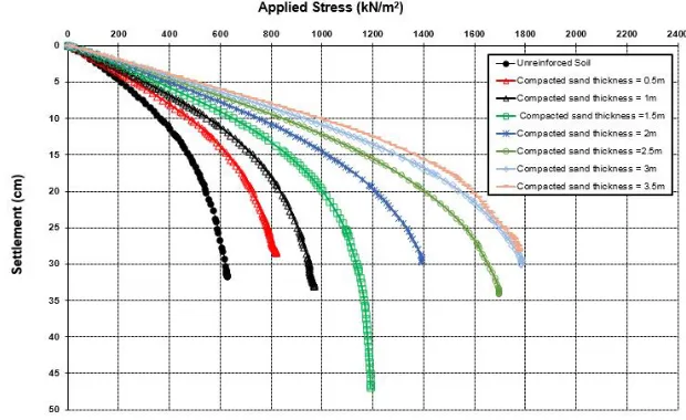
3.3 Effect of Compacted Layer Thickness
To study the effect of using compacted sand layer beneath the footing on ultimate bearing capacity the relationship between applied stress
and footing settlement was plotted as shown in Fig. 15.
It was observed that the improvement in ultimate bearing capacity of footing increased by increasing the thickness of compacted sand layer. The steady increase in bearing capacity can be attributed to the increase in the bearing resistance offered by the compacted sand layer which distributed the footing load acting on the loose sand layer over a wider area. With stronger layer of compacted sand of larger thickness, the improvement is further increased. It was observed also, that the bearing capacity of the footing increases with the increase in thickness of compacted sand layer up to a certain value of (H/B=3). Beyond this value, there is no substantial improvement in the ultimate bearing capacity. This optimum value obtained in investigation (H/B=3) is similar to value obtained by [8] using Plaxis 3d software.
s
Fig. 15. The relationship between the applied stress versus settlement in case of compacted sand layer of various thicknesses for footing width = 1m
4. CONCLUSIONS
Based on the results obtained, the following conclusions obtained:
For footings rested on layer of loose sand the effect of footing width on ultimate bearing capacity is more pronounced with footings of bigger width, where the maximum increase in bearing capacity reaches a maximum percentage of 43% when footing width increases from 1 up to 2 m.
In case of using a layer of compacted sand under the footing it was it was found that the improvement in ultimate bearing capacity of footing increased by increasing the thickness of compacted sand layer. The maximum percentage increase reaches 240%.
For case of using compacted sand layer, the optimum layer thickness obtained is three times the width of footing (h/b=3), when further increasing the thickness of compacted sand layer, it has no effect on the bearing capacity of footings.
By comparing FEM results using Plaxis software with analytical solutions by [11-12] it was concluded that FEM using Plaxis software could be used to predict bearing capacity of strip footing resting on multilayered layered subsoil system.
COMPETING INTERESTS
Authors have declared that no competing interests exist.
REFRENCES
1. Bowles JE. Foundations analysis and design. McGraw-Hill Publishing Company, New York; 1996.
2. Hanna AM. Foundations on strong sand overlying weak sand. Journal of
Geotechnical Engineering, ASCE.
1981;107(GT7):915-927.
3. Georgiadis M, Michalopoulos A. Bearing capacity of gravity bases on layered soil. Journal of Geotechnical Engineering. 1985;111(6):712-729.
4. Burd HJ, Frydman S. Discussion on bearing capacity of footings over two-layer foundation soils. Journal of Geotechnical Engineering, ASCE. 1996;122(8):699-700. 5. Abou Farah Carlos. Ultimate bearing
capacity of shallow foundations on layered soils. Concordia University, Montreal, Quebec, CANADA; 2004.
6. Kenny MJ, Andrawes KZ. The bearing capacity of footings on a sand layer overlying soft clay. Geotechnique. Mechanics and Foundations Division, ASCE. 1997;47(2):339–346,99(SM1):45– 73.
7. Okamura M, Takemura J, Kimura T. Bearing capacity predictions of sand overlying clay based on limit equilibrium methods. Soils and Foundations. 1998;38(1):181–194.
Development (IJRERD). 2017;02(04):145-154.
9. Chavda JT, Dodagoudar GR. Finite element evaluation of ultimate capacity of strip footing assessment using various constitutive models and sensitivity analysis. Innov. Infrastruct. Solut. 2018;3(15).
10. Ronald B. J. Brinkgreve, Wendy M. Swolfs. Possibilities and limitations of the finite element method for geotechnical applications. Delft University of Technology, Faculty of Civil Engineering and Geo-sciences, Geo-engineering Section; 2008.
11. Terzaghi K. Theoretical soil mechanics. Wiley, New York; 1943.
12. Vesic AS. Analysis of ultimate loads of shallow foundations. Journal of the Soil Mechanics and Foundations Division, ASCE. 1973;99(SM1):45–73.
13. Trautmann CH, Kulhawy FH. Uplift load - Displacement behavior of spread foundations. Journal of Geotechnical Engineering, ASCE. 1988;114(2):168- 183.
14. Bringkgreve RBJ, Vermeer PA. Plaxis finite element code for soil and rock analysis. Version 7 Plaxis B. V., The Netherlands; 1998.
© 2019 Radwan and Bahloul; This is an Open Access article distributed under the terms of the Creative Commons Attribution License (http://creativecommons.org/licenses/by/4.0), which permits unrestricted use, distribution, and reproduction in any medium, provided the original work is properly cited.
Peer-review history: