91 Available online at www.ijiere.com
International Journal of Innovative and Emerging
Research in Engineering
e-ISSN: 2394 - 3343 p-ISSN: 2394 - 5494
PCB Based Microwave Bandpass Passive Filter
Rachana Gandhi
a, Prof. Twinkle Doshi
aand Mr. Rajesh Deolalikar
b Student, Master of engineering, Babaria Institute of Technology, Varnama, VadodaraaHOD of EC Department, Babaria Institute of Technology, Varnama, Vadodarab
ABSTRACT:
The main goal of this research is to design, simulate and analyze modified structures of conventional parallel – coupled bandpass filter without recalculating the physical dimension, which improve the performance of filter, by minimizing spurious response at harmonic (2fc) (improving the suppression performance of 2nd harmonic
signal) and frequency response symmetry for lower cut off and upper cut off frequency characteristics.
In this paper, design of PCB based microwave bandpass passive filter is proposed to achieve high stop band rejection ratio in first harmonic about -60dB.The filter is design for three different channel Frequency band. It is design to achieve voltage standing wave ratio (VSWR) 1.5 for full band, return loss is of 15dB and insertion loss -3dB. A substrate material Flame resister (FR4) is used whose dielectric constant is 4.2. A parallel coupled method is used. This filter has a fairly stop band rejection, which makes it a good narrowband filter for outdoor application. In practical it can be helpful to each and every communication systems and high power application. The proposed filter consists of five microstrip line which are parallely coupled with each other and fed by lumped port on an electrically thin dielectric substrate. Matching network of strip lines are design using impedance matching technique and power divider rule. The all three channel filter designs are simulated by Ansoft HFSS15. The important advantages of these filters are simplicity in structure, low cost, and easy to manufacture and produce largely as printed circuits. This filter can be applicable to the every communication areas such as Wi-Fi and Wi-MAX. The parameters such as return loss, VSWR, mutual coupling and S parameter has been simulated and analyzed.
Keywords: Conventional parallel coupled, Microwave bandpass filter, (High Frequency Structure Simulator) HFSS, stop band rejection ratio, VSWR
I. INTRODUCTION
Filters are essential in the RF front end of microwave wireless communication system. In planar microstrip and stripline realization, one of the most common implementation methods for bandpass and bandstop filters with required bandwidths up to a 40% of central frequency is to use a cascade of parallel – coupled sections [1].
The synthesis procedure which consists of the design equation for the coupled line physical parameters (space-gap between parallel lines, line widths and lengths) is easy and can be found in any classical microwave books. Based on this, a well-defined systematic procedure, for the required parallel coupled microstrip – filter physical parameters can be easily derived for both Butterworth and Chebyshev’s response of any order filter [3]. The filter can be fabricated easily and it exhibits reasonably good performance compared with other planar circuit filters. Although parallel coupled bandpass microstrip – filter is very popular and simple to implement, the traditional design does suffer from a fundamental limitation, namely, the presence of spurious response at twice the basic passband at the design frequency.[4]
II. PROBLEM STATEMENT
One of the disadvantages is that the first spurious passband of this type of filter appears at twice the basic passband frequency. Therefore, the rejection of the upper stop band is worse than that of the lower stop band. For example, if coupled – line filter is used at the next stage of frequency converter, harmonic signals originated from frequency converter still exist. This causes response asymmetry in the upper and lower stop bands. Hence, this greatly limits its applications and degrades system performance. This is resulted from the inequality of even and odd mode phase velocities of coupled lines in each stage. This problem becomes severe if inverted microstrip and suspended-substrate stripline are used, since these two media exhibit considerably greater difference in mode velocities.
92 This solution, however, increases the filter layout area and introduces additional insertion losses. Hence, it is necessary to obtain a design technology that can reduce size and reject a harmonic signal. Many works have been proposed to tackle this problem.
They fall into two categories:
1. Providing different lengths for even and odd modes, 2. Equalizing the modal phase velocities.
It is found that connecting a short uncoupled line section at either end of the coupled section improves filter characteristics, if section lengths are chosen correctly. An over coupled resonator is proposed to extend phase length for the odd mode to compensate difference in the phase velocities. Subsections with a coupled three-line microstrip are inevitable at both ends of each coupled section in the filter. The capacity compensated structures are also effective in suppressing the spurious passband at 2fc. It should be noted that the loading capacitor are subject to the electrical parameters of each coupled section. Recently, combinations different stripline-stepped impedance resonators (SIR) with specified coupling angles can suppress the spurious response. The gap size and the line width for the input/output-coupled resonators are reduced to improve the rejection at 2fc. Coupled wiggly microstrip lines also show an effective suppression on the spurious passband.
The strip-width perturbation does not require the filter parameters to be recalculated, and the classical design methodology for coupled-line microstrip filters can still be used. A modified structure is proposed by applying the general ideas of the above – mentioned and Bragg condition to microstrip line to improve harmonic suppression characteristics.
III.DESIGNTECHNIQUES
This section describes the main types of distributed filters, where the various types might be used, and the major sources of design information.
A. INTERDIGITAL FILTER
Interdigital filters find most application at higher microwave Frequencies above 8 GHz or so, especially for broad bandwidths. The ideal Interdigital filter has characteristics having perfectly arithmetical symmetry, which can be of considerable advantage compared with combline filters. Such symmetry gives better phase and delay characteristics, and it is simpler to design linear. [5]
Figure 1. Interdigital filter
B. PARALLEL COUPLED FILTER
They are realized mainly in microstrip or occasionally stripline at higher microwave frequencies since excessive length precludes their economic application in low-loss airline situations. In microstrip, it is necessary to take account of the differing phase velocities between the even and odd modes in the coupled-line regions. There are several papers on this topic, but few appear to give simple design procedures that can be applied without excessive work. Bandstop filters also may take advantage of the strong coupling provided by parallel-coupled lines. Continuing with the subject of printed circuit bandpass filters, one of the more useful developments since 1984 has been the introduction of dual-mode patch and ring filters.[5]
93 C. CERAMIC BLOCK FILTER
An extremely important advance in microwave filters that has taken place since the 1984 survey is the development of ceramic. Resonator filters of the following two main types:
• Ceramic resonator or “puck” filters;
• TEM-mode coaxial cavity dielectric-resonator filters.
Ceramic resonator filters of the first type have very low loss and give a substantial reduction in the size of conventional waveguide filters. They may be either single or dual mode, but recent preference is to use single-mode designs because of better temperature stability and somewhat better performance characteristics. The two main advantages of these filters are small size, suitable for use in mobile telephones, and very low production cost. They basically consist of coaxial cavities coupled either by series capacitors or by magnetic-field coupling through the dielectric [5]. The theory is usually similar to that for air-line filters, such as combline filters in the magnetically coupled case. In some instances, dielectric may be removed from the coupling region, and an inhomogeneous structure results, requiring specialized field theory computations [6].
D. COAXIAL FILTER
This is another filter, but a more satisfactory design technique is to use the very accurate mixed lumped and distributed theory, which guarantees good performance of the filter in the entire operating band, extending to the cutoff frequency. The same theory may be applied to filters designed in any medium, such as coaxial line, stripline, microstrip, SSS, or coplanar waveguide [5].
E. WAVEGUIDE FILTER
Waveguide filter is suitable for narrow-bandwidth rectangular waveguide filters. If broader bandwidth filters are required. A high-pass filter in waveguide is usually best designed as a broad-band bandpass filter, where the upper stop band is above the desired operating band and, in any case, is often almost non-existent. In general, this results in a shorter and lower loss filter than one relying on the cutoff frequency of the waveguide. It also gives a description of dual-mode waveguide filters that are widely used in satellites and in some terrestrial systems. Waveguide low-pass filters are important, being used for harmonic rejection. Waffle-iron filters are often used, and are suitable for very broad pass bands [5]. When the pass bands are narrower, then tapered corrugated low-pass filters are usually preferred since they have lower loss, smaller size, and higher power-handling capacity. It is important to taper both broad and narrow dimensions of the waveguide to give high rejection of higher order modes in the stop bands.
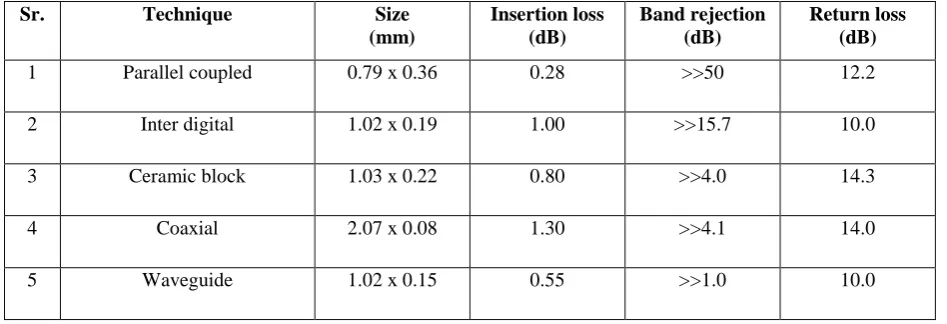
Table 1. Comparison of design techniques
Sr. Technique Size
(mm)
Insertion loss (dB)
Band rejection (dB)
Return loss (dB)
1 Parallel coupled 0.79 x 0.36 0.28 >>50 12.2
2 Inter digital 1.02 x 0.19 1.00 >>15.7 10.0
3 Ceramic block 1.03 x 0.22 0.80 >>4.0 14.3
4 Coaxial 2.07 x 0.08 1.30 >>4.1 14.0
5 Waveguide 1.02 x 0.15 0.55 >>1.0 10.0
IV.DESIGNASPECTS
A. SPECIFICATIONS:
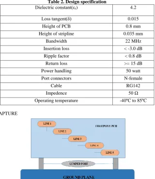
94 Table 2. Design specification
Dielectric constant(εr) 4.2
Loss tangent(δ) 0.015
Height of PCB 0.8 mm
Height of stripline 0.035 mm
Bandwidth 22 MHz
Insertion loss < -3.0 dB
Ripple factor < 0.8 dB
Return loss >= 15 dB
Power handling 50 watt
Port connectors N-female
Cable RG142
Impedence 50 Ω
Operating temperature -40ºC to 85ºC
B. SCHEMATIC CAPTURE
Figure 3. Schematic Capture of Parallel Coupled Bandpass Filter
Fig.3 shows the schematic capture of the conventional parallel coupled model of bandpass filter for particular ism frequency band. Five microstrip lines are connected with each other with parallel coupling. These strip lines are mounted on printed circuit board. At some distance ground plane is connected with PCB by two lumped port as shown in figure. Ground plane is assigned by aluminum.
C. SIMULATION AND RESULT
95 Figure 5. 3D view of BPF with lumped port in HFSS
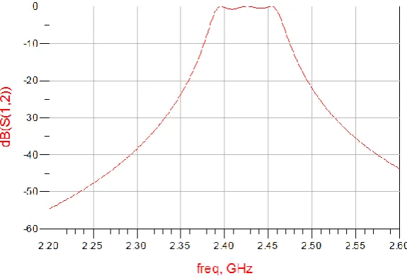
Figure 6. Stop band Rejection
V. CONCLUSIONS
The frequency response of such a resonator is comparable to that of a first-order filter the central bandwidth. The use of these resonators significantly increases the out-of-band rejection once the transmission zeros have been properly placed to create and control the width of two attenuated bands. The design principles have been discussed and validated through theoretical and experimental comparisons. Some additional effort needs to be made in order to take into account possible parasitic coupling. If parasitic coupling is not a problem here, according to the electrical specification of the chosen filter and of the dielectric substrate characteristics, i.e., thickness and dielectric constant, it can become very important in other cases. Consequently, it should not be neglected and we are presently working on it.
ACKNOWLEDGMENT
96 REFERENCES
[1] “Compact microstrip parallel coupled Bandpass filter with a Centre frequency of 2.4 GHz suitable for Bluetooth and GPS communication”: India 2nd International Conference on Signal Processing and Integrated Networks (SPIN), IEEE, Pushpendu Bikas Saha, Sourav Roy, Manik Bhawmik NIT Agartala, Tripura 2015
[2] “Parametric Effect of Defected Ground Structure (DGS) on Frequency of a Bandpass Filter”: IEEE conference paper, M. T. Khan, M. A. Zakariya, M. N. M. Saad, Z. Baharudin, M. Z. Ur Rehman Department of Electrical and Electronics Engineering 2014
[3] “Design and Simulation of a Parallel-Coupled Microstrip Bandpass Filter”: IEEE conference paper Shujun Yang, Deandre Cross, and Michael Drake Department of Electrical Engineering and Computer Science Alabama A&M University, Huntsville, 2014
[4] “A Multi-layered Parallel Coupled Microstrip Bandpass Filter With Embedded SIR Cells to Have a Broad Upper Rejection Band”: IEEE microwave and wireless components letters, vol. 20, no. 1, Hon Kuan, Yueh-Ling Lin, Ru-Yuan Yang, Member, IEEE, and Yu-Chi Chang, January 2010
[5] “Design of Microwave Filters”: IEEE Transactions On Microwave Theory And Techniques, Vol. 50, No. 3, Ralph Levy, Life Fellow, IEEE, Richard V. Snyder, Fellow, IEEE, And George Matthaei, Fellow, IEEE, March 2002 [6] “Narrow Bandpass Filters Using Dual-Behavior Resonators”: IEEE transactions on microwave theory and techniques,