Scholarship at UWindsor
Scholarship at UWindsor
Electronic Theses and Dissertations
Theses, Dissertations, and Major Papers
2013
Hardware JPEG Decompression
Hardware JPEG Decompression
Dan MacDonald
University of Windsor
Follow this and additional works at:
https://scholar.uwindsor.ca/etd
Recommended Citation
Recommended Citation
MacDonald, Dan, "Hardware JPEG Decompression" (2013). Electronic Theses and Dissertations. 4889.
https://scholar.uwindsor.ca/etd/4889
This online database contains the full-text of PhD dissertations and Masters’ theses of University of Windsor
students from 1954 forward. These documents are made available for personal study and research purposes only,
in accordance with the Canadian Copyright Act and the Creative Commons license—CC BY-NC-ND (Attribution,
Non-Commercial, No Derivative Works). Under this license, works must always be attributed to the copyright holder
(original author), cannot be used for any commercial purposes, and may not be altered. Any other use would
require the permission of the copyright holder. Students may inquire about withdrawing their dissertation and/or
thesis from this database. For additional inquiries, please contact the repository administrator via email
Hardware JPEG Decompression
by
Dan MacDonald
A Thesis
Submitted to the Faculty of Graduate Studies through the
Department of Electrical and Computer Engineering in Partial Fulfillment
of the Requirements for the Degree of Master of Applied Science at the
University of Windsor
All Rights Reserved. No Part of this document may be reproduced, stored or
oth-erwise retained in a retreival system or transmitted in any form, on any medium by
Hardware JPEG Decompression
by
Dan MacDonald
APPROVED BY:
Boubakeur Boufama
Computer Science
Huapeng Wu
Electrical and Computer Engineering
Roberto Muscedere, Advisor
Electrical and Computer Engineering
I hereby certify that I am the sole author of this thesis and that no part of this thesis
has been published or submitted for publication.
I certify that, to the best of my knowledge, my thesis does not infringe upon
any-ones copyright nor violate any proprietary rights and that any ideas, techniques,
quotations, or any other material from the work of other people included in my
the-sis, published or otherwise, are fully acknowledged in accordance with the standard
referencing practices. Furthermore, to the extent that I have included copyrighted
material that surpasses the bounds of fair dealing within the meaning of the Canada
Copyright Act, I certify that I have obtained a written permission from the copyright
owner(s) to include such material(s) in my thesis and have included copies of such
copyright clearances to my appendix.
I declare that this is a true copy of my thesis, including any final revisions, as
ap-proved by my thesis committee and the Graduate Studies office, and that this thesis
Abstract
Due to the ever increasing popularity of mobile devices, and the growing number of
pixels in digital photography, there becomes a strain on viewing one’s own photos.
Similar to Desktop PCs, a common trend occurring in the mobile market to
com-pensate for the increased computational requirements is faster and multi-processor
systems. The observation that the number of transistors in integrated circuits doubles
approximately every 18-24 months is known as Moore’s law. Some believe that this
trend, Moore’s law, is plateauing which enforces alternate methods to aid in
compu-tation.
This thesis explores supplementing the processor with a dedicated hardware
mod-ule to reduce its workload. This provides a software-hardware combination that can
be utilized when large and long computations are needed, such as in the decompression
of high pixel count JPEG images. The results show that this proposed architecture
Acknowledgments
I will always be grateful to my supervisor, Dr. Muscedere, for his vast knowledge,
advice, and for bringing this challenging project to my attention.
I’d also like to thank my other committee members, Dr. H. Wu and Dr. B.
Boufama, for their support in this research. Lastly, I’d like to thank my dog Maxx
Declaration of Originality
iv
Abstract
v
Dedication
vi
Acknowledgments
vii
List of Figures
xii
List of Tables
xiv
List of Abbreviations
xvi
1
Introduction
1
1.1
History of JPEG Images . . . .
2
1.2
Overview of Research, Motivation . . . .
3
1.3
Organization of Thesis . . . .
4
2
The JPEG Standard
6
CONTENTS
2.2
Quantization
. . . .
10
2.3
Huffman Encoding and Decoding . . . .
11
2.4
Field Programmable Gate Array . . . .
14
2.4.1
Soft Processor . . . .
14
2.5
Summary
. . . .
15
3
Existing Work in Hardware JPEG Algorithms
16
3.1
libjpeg . . . .
17
3.2
Inverse Discrete Cosine Transform (IDCT) . . . .
18
3.2.1
Distributed Arithmetic DCT . . . .
19
3.2.2
Loeffler Algorithm
. . . .
20
3.3
YCC to RGB Colour Space Conversion . . . .
22
3.3.1
Look Up Table . . . .
24
3.3.2
Shift and Add . . . .
25
3.3.3
Integer Based Transform . . . .
26
3.4
Summary
. . . .
27
4
Proposed Hybrid Architecture
28
4.1
Development Board Specs . . . .
29
4.2
Hardware Software Communication . . . .
30
4.2.1
Communication through DDR2 RAM . . . .
31
4.2.2
Communication through Hardware Registers . . . .
32
4.3
Hardware Design . . . .
33
4.3.1
IDCT
. . . .
33
4.4
Software Design . . . .
38
4.4.1
IDCT
. . . .
38
4.4.2
Colour Conversion
. . . .
40
4.5
Summary
. . . .
41
5
Results
43
5.1
Testing Setup and Procedure . . . .
43
5.2
Timing Results . . . .
46
5.2.1
Hardware Timing . . . .
49
5.3
Image Verification . . . .
50
5.4
Summary
. . . .
55
6
Conclusion and Recommendations
56
6.1
Recommendations . . . .
57
References
59
A Source Images
61
B Testing Scripts
63
C C Code
66
C.1 libjpeg modifications . . . .
66
C.2 ReadImage.c . . . .
74
CONTENTS
D.2 Colour Converter . . . .
95
E Huffman Decoding Example
105
E.1 Source Image . . . .
105
E.2 Huffman Table Extraction . . . .
108
E.3 Image Decoding . . . .
109
E.3.1
Block 1 - Luminance . . . .
109
E.3.2
Block 1 - Chrominance . . . .
110
E.3.3
Block 2 - Luminance . . . .
111
E.3.4
Block 2 - Chrominance . . . .
112
E.4 Finalizing . . . .
113
E.5 Huffman Tables . . . .
114
2.1
JPEG Compression Process [13] . . . .
7
2.2
JPEG Decompression Process [13] . . . .
7
2.3
Energy Compaction of the DCT . . . .
9
2.4
Zig Zag order of a DCT block [13] . . . .
9
2.5
Huffman Tree . . . .
13
3.1
Desktop JPEG Profiling . . . .
18
3.2
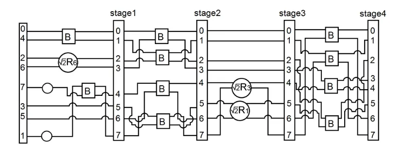
Loeffler Algorithm for 1D DCT . . . .
21
3.3
Loeffler Algorithm for 1D IDCT . . . .
22
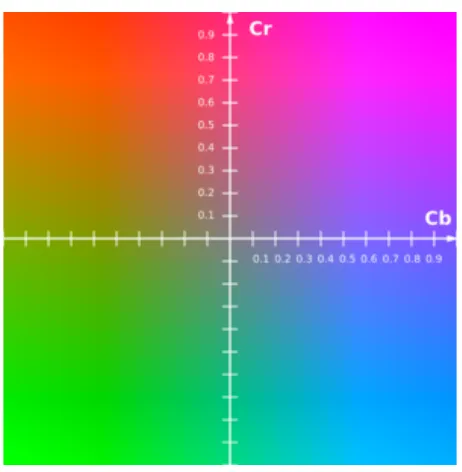
3.4
Cb-Cr colour plane at a constant luma value . . . .
23
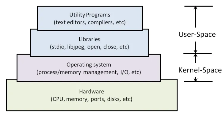
4.1
Layers of a GNU/Linux based embedded system . . . .
31
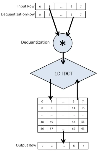
4.2
Dequantization and 2D-IDCT Hardware Design . . . .
35
4.3
YCC to RGB Hardware Design . . . .
38
4.4
IDCT array-register data compaction . . . .
39
4.5
3D image array . . . .
40
LIST OF FIGURES
5.1
Image Decompression Timing . . . .
48
5.2
Image Decompression Timing . . . .
49
5.3
Bookstore image byte offset histogram
. . . .
51
5.4
Dog image byte offset histogram . . . .
52
5.5
beach image byte offset histogram . . . .
53
A.1 Sample 20MP images . . . .
62
E.1 Sample image . . . .
106
E.2 HEX dump from sample image
. . . .
106
2.1
Example Huffman data . . . .
12
3.1
Butterfly[B], Rotator[R], and constant Multiplication Blocks for
Loef-fler’s Algorithm . . . .
21
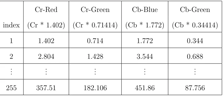
3.2
Colour Space Look Up Table example . . . .
24
4.1
YCC - RGB constants . . . .
37
5.1
Test Image Dimensions . . . .
46
5.2
Bookstore Image Results . . . .
47
5.3
Dog Image Results . . . .
47
5.4
Beach Image Results . . . .
47
5.5
Hardware Only Timing per test image
. . . .
50
5.6
Test Image Verification . . . .
54
E.1 Huffman Decoding Results . . . .
113
E.2 Huffman Luminance (Y) DC table . . . .
114
E.3 Huffman Luminance (Y) AC table . . . .
115
LIST OF TABLES
E.5 Huffman Chrominance (Cb and Cr) AC table
. . . .
117
LIST OF ABBREVIATIONS
1D
1 Dimensional
2D
2 Dimensional
ASIC
Application Specific Integrated Circuit
CPU
Central Processing Unit
DCT
Discrete Cosine Transform
DSP
Digital Signal Processing
FDCT
Forward Discrete Cosine Transform
FPGA
Field Programmable Gate Array
HDL
Hardware Description Language
HW
Hardware
IDCT
Inverse Discrete Cosine Transform
JPEG
Joint Photographic Experts Group
LUT
Lookup Table
MP
Megapixel
px
pixels
RAM
Random Access Memory
RISC
Reduced Instruction Set Computer
SOC
System On Chip
SW
Software
RGB
Red Green Blue
VHDL
VHSIC Hardware Description Language
VHSIC
Very High Speed Integrated Circuit
Introduction
In recent years digital photography has taken leaps and bounds in the consumer
mar-ket. Along with improved sensors, functions, and touch screens, the pixel count of
the images are steadily increasing. At the time of writing this thesis, a consumer can
purchase a digital camera capable of taking a JPEG image of, 20 million pixels (20
MP). Additionally there has been an explosion with mobile devices such as smart
phones and tablets. The trend that the number of transistors in integrated circuits
doubles approximately every 18-24 months is known as Moore’s law [9]. Following
this trend, mobile processors are approaching the speed and multi-core architectures
of their desktop counterparts. A pocket sized computer has its advantages, but it
does face challenges when viewing the growing size of multi-media, especially digital
1. INTRODUCTION
By far the most popular form digital image in computing today is the JPEG
(Joint Photographic Experts Group) image. JPEG images are found in every digital
camera, photo editing suites, MPEG video, internet browsers, and video games to
name a few. As all of the photo albums, and every photo taken become digitized into
JPEGs, being able to comfortably view the images becomes necessary.
1.1
History of JPEG Images
Early in computing history a need for viewing digital images arose. However, with
limited memory and storage space, raw image data was not a feasible solution. In
1986 a committee, the Joint Photographic Experts Group (JPEG) [4], was formed
to create a standard for digitized images. The JPEG group worked to standardize
a method of coding still pictures, known as JPEGs. The JPEG standard outlines a
codec that defines how an image is compressed into a stream of bytes and
decom-pressed back into an image.
The JPEG standard was first publicly released in 1992, which was approved as
ITU-T Recommendation T.81 and in 1994 as ISO/IEC 10918-1. Two years later the
standard was updated to include rules and checks for software conformance. Several
parts of the standard have been added in the years since, which introduce features
such as the JPEG File Interchange Format(JFIF), that outlines the structure of the
The focus of the JPEG codec is to preserve as much data as possible while
com-pressing it into a much smaller file size. Due to this fact, JPEG images are considered
a lossy compression. By default they have a high degree of compression, with
min-imal perceptible loss in image quality but this can be adjusted. Adjustment of the
compressions ratio results in a tradeoff between data losses and file size. Higher
com-pression ratio have smaller file size, and vice versa. The JPEG standard provides
a framework for image compression and decompression, but depending on the
algo-rithms used determines the different types of JPEGs. A few types are progressive
sequential, lossless and baseline sequential. By far the most common type is Baseline
Sequential. The standard provides a simple and efficient algorithm which makes it
suitable for all digital cameras.
1.2
Overview of Research, Motivation
The accelerating popularity of mobile devices, and exploding pixel counts found in
consumer grade digital cameras have lead to an issue when attempting to view ones
own images. Many software applications have employed techniques when
display-ing larger images, such as computdisplay-ing display sized thumbnails. However
pre-computation of a digital photo album does not resolve the problem, nor are these
techniques future proof against large device screen sizes, resolution, and increasing
1. INTRODUCTION
The focus of this thesis is to present an alternative architecture to relieve
compu-tations from the CPU and therefore improve upon the delay mobile devices undergo
when accessing large JPEG images. Currently there are dedicated hardware modules
for audio and video playback, but nothing has been done for still images. This work
is implemented on an embedded FPGA Linux platform using a JPEG decoding
soft-ware library found in the majority of mobile devices.
This thesis demonstrates the capability of dedicated hardware to assist the CPU
in computational workloads. It primarily focuses on reducing delays from the
mathe-matically challenging two-dimensional inverse discrete cosine transform (IDCT), and
the colour conversion from the luminance, and chrominance channels to the red, green,
blue colour system frequently used in digital displays. It achieves improvements from
hardware and software optimizations.
1.3
Organization of Thesis
Chapter 1 begins with an introduction to JPEG images and the JPEG ISO Standard,
then continues with a brief introduction to digital photography and trends in the
mobile market. Chapter 2 elaborates on the JPEG standard, describing the necessary
steps used to compress and decompress raw data to and from a viewable image.
Chapter 3 discusses previous works which aid in specific algorithms used by the JPEG
standard. Chapter 4 proposes a new software-hardware hybrid architecture used to
timing results, and verification of the hybrid architecture. Chapter 6 concludes this
Chapter 2
The JPEG Standard
The JPEG standard for compression of still images [13], outlines the processes which
must be utilized to complete the JPEG compression or decompression. The standard
is comprised of 3 primary transformations which are reversible. In this chapter, the
methods and guidelines of the JPEG standard are reviewed, followed by a brief
in-troduction to Field Programmable Gate Arrays (FPGAs) and embedded systems.
The JPEG compression process consists of the Forward Discrete Cosine
Trans-form(FDCT), quantization of the DCT coefficients, and encoding the remaining
val-ues into binary representations as shown in Figure 2.1.
compres-Figure 2.1: JPEG Compression Process [13]
Figure 2.2: JPEG Decompression Process [13]
sion in the reverse and inverse order. Decoding the binary values, dequantization, and
the Inverse Discrete Cosine Transform(IDCT) to obtain the original image content as
shown in Figure 2.2.
2.1
Discrete Cosine Transform
The Forward Discrete Cosine Transform(FDCT) is commonly referred to as the
2. THE JPEG STANDARD
degree of compression with minimal losses. Equation 2.1 shows the 1 dimensional
DCT (1D-DCT) of length 8. In JPEG image processing, Figure 2.1, the DCT is
per-formed 2 dimensionally (2D-DCT) on 8x8 blocks as shown in Equation 2.2, in which
the 1D-DCT is applied to each row, followed by each column.
F
(
k
) =
α
(
k
)
7X
x=0
f
(
x
) cos(
(2
x
+ 1)
kπ
16
)
α
(
k
) =
r
1
8
f or k
= 0
α
(
k
) =
1
2
otherwise
(2.1)
F
(
u, v
) =
1
4
C
(
u
)
C
(
v
)
7X
x=0 7
X
y=0
f
(
x, y
) cos(
(2
x
+ 1)
uπ
16
) cos(
(2
y
+ 1)
vπ
16
)
C
(
u
)
, C
(
v
) =
√
1
2
f or u, v
= 0
C
(
u
)
, C
(
v
) = 1
otherwise
(2.2)
As a result the output of the 2D-DCT focuses its energy in the upper left corner
of the 8x8 block, causing most of the 8x8 block to be zero. Figure 2.3 illustrates the
energy compaction of one row of pixels. Encoding of the DCT block can then be
optimized with the zig-zag pattern in Figure 2.4. Thus the trailing zeros can further
Figure 2.3: Energy Compaction of the DCT
Figure 2.4: Zig Zag order of a DCT block [13]
In the JPEG decompression, Figure 2.2, process the Inverse Discrete Cosine
Trans-form (IDCT) is utilized to transTrans-form the dequantized Huffman coefficients back into
2. THE JPEG STANDARD
2D-DCT. Similar to the DCT, the IDCT is a row-column transformation.
f
(
x, y
) =
1
4
7
X
u=0 7
X
v=0
C
(
u
)
C
(
v
)
F
(
u, v
) cos(
(2
x
+ 1)
uπ
16
) cos(
(2
y
+ 1)
vπ
16
)
C
(
u
)
, C
(
v
) =
√
1
2
f or u, v
= 0
C
(
u
)
, C
(
v
) = 1
otherwise
(2.3)
2.2
Quantization
The quantization transformation shifts the output of the DCT down with integer
rounded division to increase the compression shown in Equation 2.4. Smaller
num-bers use fewer bits which achieves higher compression. The factor at which the DCT
coefficients are divided is determined by the quantization matrix. The quantization
matrix is a statistically determined matrix where the higher valued coefficients at the
top left of the matrix receive more scaling than the rest. This is due to the fact that
the output of the DCT focuses its energy at this corner. In most JPEGs the
quanti-zation matrices are not statistically determined for that particular image, instead a
generic set of tables based on the human vision system and trends from the DCT are
F
Q(
u, v
) =
IntegerRound
(
F
(
u, v
)
Q
(
u, v
)
)
(2.4)
Dequantization is the reverse of quantization where the inputs to the IDCT are
multiplied by the same quantization matrix to scale up the coefficients to the original
intended value as shown in Equation 2.5.
F
Q0(
u, v
) =
F
Q(
u, v
)
∗
Q
(
u, v
)
(2.5)
2.3
Huffman Encoding and Decoding
The final component of the JPEG compression/decompression process is entropy
en-coding/decoding. Encoding is the process of converting data from one format to
another for the purposes of speed, security or space saving. The purpose of entropy
encoding/decoding used in JPEG images is to compress the data without any losses.
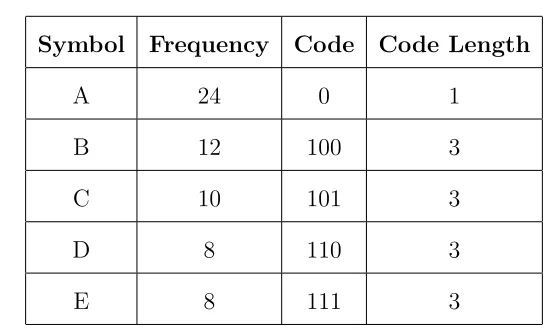
The most common type of JPEG image is baseline sequential, which use Huffman
encoding/decoding [6]. Huffman encoding achieves lossless compression by allocating
the most frequently used symbols with the fewest number of bits. The example data
2. THE JPEG STANDARD
Symbol
Frequency
Code
Code Length
A
24
0
1
B
12
100
3
C
10
101
3
D
8
110
3
E
8
111
3
Table 2.1: Example Huffman data
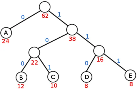
Based on the frequency of the symbol, a Huffman tree in Figure 2.5 is constructed.
Most frequently used symbols are near the top of the tree, and the less frequent are
at the bottom. A ”move” down the right branch of the tree represents a ”1”, and a
”move” down the left branch represents a ”0”
Eg: Symbol ’C’ is allocated the bits ”101”, while the most common symbol ’A’
Figure 2.5: Huffman Tree
Using this method the Huffman encoding creates a much smaller encoded bit
stream. Instead of building a Huffman tree each time, the JPEG image includes a
set of tables giving the bit to number translations. For decoding a set of 4 tables
are created. The tables are categorized by the colour channel, and frequency type:
Luminance DC, Luminance AC, Chrominance DC, and Chrominance AC. The two
Chrominance channels(Cb, Cr) share the AC and DC tables.
Huffman decoding is the reverse process of encoding. With the provided tables
and compressed bitstream the values can be perfectly reconstructed during JPEG
decompression. In many digital imaging devices such as digital cameras, the
Huff-man symbol calculations for that image are not calculated and a set of statistically
determined tables are used instead. Utilizing the default set of tables allows for faster
image compression, but can create a larger file size. In programs such as image
2. THE JPEG STANDARD
which result in a smaller file size, but more computation time.
2.4
Field Programmable Gate Array
A Field Programmable Gate Array (FPGA) is an integrated circuit designed to be
configurable after manufacture. Using design tools, an FPGA can be programmed to
generate the logic for virtually any hardware configuration. Unlike common CPU
ar-chitectures, since FPGAs are effectively programmable hardware it has the capability
to perform computations in parallel. This attribute greatly enhances speed over the
conventional methodology.
Many embedded systems, specifically those in mobile devices consist of a complete
system on chip (SOC). Additional hardware such as peripherals, are added either
in-ternally or exin-ternally. The use of FPGAs provide a flexible development platform
without the cost of a conventional SOC design. This work utilizes an FPGA which
models a SOC and its peripherals. The FPGA platform makes this work a suitable
platform and allows testing in real time.
2.4.1
Soft Processor
A soft processor is a microprocessor core that can be entirely implemented in using
logic synthesis. For FPGAs a soft processor design can mimic the Reduced Instruction
MicroB-laze processor [1] used in this work is a soft processor designed for Xilinx FPGAs. The
MicroBlaze is implemented entirely in the general-purpose memory and logic fabric
of Xilinx FPGAs.
2.5
Summary
This chapter discussed the methods outlined in the JPEG standard used to compress
and decompress JPEG image data, as well as gave an introduction to FPGAs in
em-bedded systems.
Due to the fact that the JPEG is highly complex, this research focuses on
opti-mizing individual components of the JPEG decompression process rather than the
entire algorithm. Utilizing the configurability of FPGAs a hardware architecture can
be designed to improve the software functions. This hybrid software-hardware
Chapter 3
Existing Work in Hardware JPEG
Algorithms
The JPEG ISO standard, described in Chapter 2, outlines the transforms that are
needed in order to compress and decompress JPEG images. It does not describe the
specific algorithms that need to be used to achieve the end product. There hasn’t
been much publicized work on the complete decompression of a JPEG, but there
has been some work in the individual algorithms used to decompress a JPEG image.
This chapter will begin with an introduction to libjpeg, the most commonly used
JPEG software library used in mobile systems, followed by the state of the art in the
3.1
libjpeg
There has been much work done in the software compression and decompression of
JPEG images. In 1986, shortly after the JPEG standard was created a group called
the Independent JPEG Group [7] (IJG) created the free open-source C library called
”libjpeg”. The library is multi-platform configurable, and follows all of the JPEG
ISO standards, and as such libjpeg is credited by the JPEG group to being a reliable
source to use in software applications. Due to its longevity and popularity libjpeg
has found itself as the primary JPEG encoder/decoder in mobile device applications,
as well as desktop applications. For this reason, this work uses the libjpeg ported for
the Xilinx MicroBlaze architecture as the starting point and control for testing.
Chapter 2 outlined the three primary steps used in compression and
decompres-sion, however these algorithms are not necessarily the most costly functions in the
digital domain. Therefore, the libjpeg library was profiled (a process of timing the
functions in software to find where the most significant bottlenecks reside) and
ex-amined.
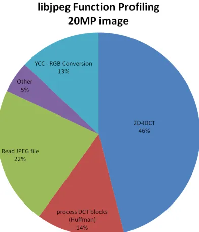
To acquire an approximate function benchmark a 20 MP image was profiled on
a desktop PC running a Pentium-4 3GHz processor, 32-bit GNU/Linux operating
system, and 2GB of RAM. The image was profiled 100 times and averaged to achieve
statistical accuracy. Figure 3.1 displays the profiling results.
3. EXISTING WORK IN HARDWARE JPEG ALGORITHMS
Figure 3.1: Desktop JPEG Profiling
colour space conversion, and the Huffman transform with 46%, 13%, and 14%
respec-tively. The focus of this work centres on optimizing the IDCT and colour conversion
to enhance the JPEG decompression time.
3.2
Inverse Discrete Cosine Transform (IDCT)
First introduced in Section 2.1 the IDCT is the Inverse of the Discrete Cosine
Trans-form which used to transTrans-form the output of raw dequantized Huffman coefficients.
For JPEG images the pixels are split into 8x8 blocks prior to applying the DCT. The
2D-IDCT consists of 16 1D-IDCTs over the 8 rows and 8 columns of the DCT blocks.
8x8 JPEG blocks.
f
(
x, y
) =
1
4
7X
u=0 7X
v=0C
(
u
)
C
(
v
)
F
(
u, v
) cos(
(2
x
+ 1)
uπ
16
) cos(
(2
y
+ 1)
vπ
16
)
C
(
u
)
, C
(
v
) =
√
1
2
f or u, v
= 0
C
(
u
)
, C
(
v
) = 1
otherwise
(3.1)
The traditional IDCT in equation 3.1 shows the iterative multiplication process.
3.2.1
Distributed Arithmetic DCT
The Distributed Arithmetic DCT (DA-DCT) proposed by Pan [10] attempts to reduce
the complexity of the DCT by exploiting the binary representations of the 2D-DCT
matrix. The number of additions in this transform are reduced by a factor of 22.
On average 1 multiplication, 40 additions, and 16 binary shifts are required for each
DCT coefficient. Equations 3.2 - 3.6 illustrate how the transform is performed.
Y
=
A
∗
X
=
A
1A
2· · ·
A
L
X
1X
2..
.
X
L
(3.2)
A
k=
−
A
Mk2
M+
M−1
X
i=N
A
ik2
iwhere
A
ikis 0 or 1
3. EXISTING WORK IN HARDWARE JPEG ALGORITHMS
Y
= 2
N∗
−
2
M−N2
M−N−1· · ·
2 1
|
{z
}
S
∗
A
M1
A
M2· · ·
A
MLA
M1 −1A
M2 −1· · ·
A
ML−1..
.
..
.
· · ·
..
.
A
N1A
N2· · ·
A
NL
|
{z
}
B
∗
X
1X
2..
.
X
L
|
{z
}
X
![Figure 2.1: JPEG Compression Process [13]](https://thumb-us.123doks.com/thumbv2/123dok_us/1422109.1174750/25.612.120.522.127.462/figure-jpeg-compression-process.webp)
![Figure 2.4: Zig Zag order of a DCT block [13]](https://thumb-us.123doks.com/thumbv2/123dok_us/1422109.1174750/27.612.118.531.128.344/figure-zig-zag-order-dct-block.webp)