Copyright © 2013 IJECCE, All right reserved
Low-Cost PIR Sensor Based Security System Using
Micro Controller
S. Sandeep
Assistant Professor Department of ECE SVPCET, Puttur
C. Manikanta
Assistant Professor Department of ECE SVPCET, Puttur
P. Rajasekhar
Assistant Professor Department of ECE SVPCET, Puttur
C. Kumar
Associate Professor Department of ECE SVPCET, Puttur
Abstract–This paper proposes the development of a Low-cost security system using small PIR (Pyroelectric Infrared) sensor built around a microcontroller. The low-power PIR detectors take advantage of pyroelectricity to detect a human body that is a constant source of Passive Infrared (radiation in the infrared region). The system senses the signal generated by PIR sensor detecting the presence of individuals not at thermal equilibrium with the surrounding environment. Detecting the presence of any unauthorized person in any specific time interval, it triggers & sets up a message to a predefined number through a GSM modem. This highly reactive approach has low computational requirement, therefore it is well-suited to surveillance, industrial applications and smart environments. Tests performed gave promising results
Keywords – Fresnel Lens, GSM, Infrared, PIC, PIR Module, Pyroelectricity.
I. I
NTRODUCTIONSecurity and safety is one of the most talked of topics in almost every facet like surveillance, industrial applications, offices, and in general, in smart environments. To secure it against theft, crime, fire, etc. a powerful security system is required not only to detect but also pre-empt hazards. Conventional security systems use cameras and process large amounts of data to extract features with high cost and hence require significant infrastructures. This paper proposes a PIR sensor based low cost security system for home applications in which Passive Infrared (PIR) sensor has been implemented to sense the motion of human through the detection of infrared radiated from that human body. PIR device does not emit an infrared beam but passively accepts incoming infrared radiation. Fig.1 shows the block diagram of the system. PIR sensor detects the presence of human in the home and generates pulse which is read by the microcontroller. According to the pulse received by microcontroller, a call is established to mobile station through a GSM modem and thus warns the presence of human in the home to owner-occupier. On the other hand, this security system remains in idle position and performs nothing if no one is in the home. This paper is organized into eight sections, including this section. Section II discusses some related works and section III presents an overview of PIR sensors and detection process. Circuit diagram and operation details are in section IV and V respectively.
Infrared Radiation
Fig.1. System block diagram
The application flowchart is given in section VI. Section VII discusses the experimental results of the implemented prototype system. Finally, future improvements and the conclusions are presented in section VIII.
II. R
ELATEDW
ORKSIII. PIR S
ENSORPIR is basically made of Pyroelectric sensors to develop an electric signal in response to a change in the incident thermal radiation. Every living body emits some low level radiations and the hotter the body, the more is emitted radiation. Commercial PIR sensors typically include two IR-sensitive elements with opposite polarization housed in a hermetically sealed metal with a window made of IR-transmissive material (typically coated silicon to protect the sensing element). When the sensor is idle, both slots detect the same amount of IR, the ambient amount radiated from the room or walls or outdoors. When a warm body like a human or an animal passes by, it first intercepts one half of the PIR sensor[4] which causes a positive differential change between the two halves. When the warm body leaves the sensing area, the reverse happens, whereby the sensor generates a negative differential change. These change pulses are what is detected. In order to shape the FOV, i.e. Field Of View of the sensor, the detector is equipped with lenses in front of it. The lens used here is inexpensive and lightweight plastic materials with transmission characteristics suited for the desired wavelength range. To cover much larger area, detection lens is split up into multiple sections, each section of which is a Fresnel lens. Fresnel lens condenses light. Providing a larger range of IR tothe sensor it can span over several tens of degree width. Thus total configuration improves immunity to changes in background temperature, noise or humidity and causes a shorter settling time of the output after a body moved in or out the FOV. Along with pyroelectric sensor, a chip named Micro Power PIR Motion Detector IC has been used. This chip takes the output of the sensor and does some minor processing on it to emit a digital output pulse from the analog sensor. Schematic of PIR sensor output waveform is shown in Fig. 2.For triggering purpose, there are three dedicated pins in the PIR module: HIGH, LOW and COMMON. When connecting up LOW and COMMON pins, the output turns on and off every second or so when moving in front of it. That is called "non-retriggering" and shown in Fig. 3(a). When connecting up HIGH and COMMON pins, the output stay on the entire time that something is moving. That is called "retriggering" and shown in Fig. 3(b).
Fig.2. PIR sensor output wave form
Fig.3. (a) non-triggering (b) re triggering.
IV. W
ORKINGC
IRCUITCopyright © 2013 IJECCE, All right reserved Fig.4. Sensor and signal processing segment
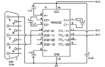
Figure 5.GSM modem interfacing segment The power pin is connected to iQl output pin of the O-iatch ie. The alann can be set to ring by MCU. - MCU: Pin RC4 of PIC 16f876A is connected to the 0 1 input of 74LS75. C. GSM Modem interfacing segment: This segment is shown in Fig. 6. As GSM modem uses serial communication to interface with other peripherals, aninterface is needed between MCU and GSM modem. This segment consists of four parts: -OB9 male connector: The serial port used here is a 9 pinOB9 male connector as the GSM modem side uses a female connector. Pin 14 and 13 of MAX232 are connected to pin 2 and 3 ofOB9 respectively. Pin 5 ofOB9 is grounded. - MAX232: This particular IC is necessary for increasing the voltage swing at the outputs. It takes OV and +5V inputs and makes it a + 12V and - 12V output voltages. This increased voltage swing is a requirement for serial communications. Two 1 /IF capacitors are connected between pins 4, 5 and 1, 3 of MAX232. V+ and V- pins are fed from VCC and GNO, i.e. G round through two 1 /IF capacitors. Between VCC and GNO pins, one 10 /IF capacitor is placed.- GSM modem: GSM modem is connected through a OB9 female connector to the interfacing circuit. - MCU: The VCC, i.e. power pin, TTL input and TTL output pins of MAX232 are connected to the pins RCO, RCI and RC2 of MCU respectively.
V. C
IRCUITO
PERATIONA. Sensor and signal processing segment:
As the jumper of PIR sensor module is placed between C and H, the output will stay on the entire time something ismoving. The regulator IC serves regulated +5V to the LM35 and PIR sensor module. Prior to any operation, external interrupt is disabled in software of MCU. When the mechanical switch is closed, pin RBO gets an input voltage. This sets the system to run. The analog voltage output from LM35 is taken and converted to an equivalent binary value which represents the ambient temperature. As PIR sensor module does not perfonnsatisfactorily below 15°C temperature, MCU monitors the temperature and light LED on pin RC3 when the temperature is equal to or greater than the critical temperature [5]. After the LED is on, the MCU waits a pre-defined time for the place to be fully evacuated. After that time is over, the system is online. After activation of the system, if there is any movement on that place within the coverage region of the PIR sensor module, it outputs a pulse which is taken as input by MCU. MCU then waits a pre defined time and checks for that signal again. This is done for avoiding false triggering.
B. Alarm segment:
RC4 remains HIGH right from the beginning. Thus, the output pin IQ of 74LS75 stays LOW and the alarm does not ring. If the signal is still present during the second check, MCU makes pin RC4 LOW. This makes a HIGH on IQ of 74LS75 and the alarm rings.C. GSM Modem interfacing segment:
MCU makes HIG H on RCO which in tum, activates MAX232 Ie. Then MCU starts sending AT commands to the GSM modem through the pins RCI and RC2. The commands are sent through the interface to the modem. The modem receives the commands and sets up a call to a pre-defined number. The call is not disconnected until the call time - up or the recipient disconnects the call. After the call is disconnected, MCU goes to SLEEP, i.e. low power consuming mode. Before going into SLEEP, MCU enables the external interrupt in software. When the mechanical switch is open, an interrupt occurs and MCU is brought out of SLEEP mode.VI. S
OFTWAREpre-defined time before executing any instruction. This wait state is introduced to ensure proper evacuation of the place where the system is to run. After the wait state is over, MCU starts checking for any signal from the PIR sensor module. When there is no signal from the sensor, MCU checks the status of the switch. If the switch is still closed, it continues to check for sensor signal. But, if the switch is opened, MCU breaks out of the signal checking loop and waits for the switch to be closed again. Whenever the input signal state is HIGH on RBI, MCU begins waiting for a pre-defined time. This wait state is introduced to ensure avoidance of the false triggering as the output pulse from the PIR sensor module stays HIGH for a specific time depending on the resistor and capacitor values [6]. Then MCU checks again for the input signal on RB 1. If MCU does not find the signal HIGH, it will jump back to the first motion detection loop. But, if the signal is still HIGH, MCU interprets it as the true detection of motion of any warm body. In this case, MCU will sound the alarm and send proper AT commands to the GSM modem to initiate a call to a pre-defined number. After setting up the call, MCU will wait for a pre-defined time before executing next instructions. This wait state allows the call to be completed successfully. After that, MCU enables the external interrupt and goes to SLEEP mode. Enabling the external interrupt prior to SLEEP mode ensures that MCU will wake from the SLEEP mode whenever there is a HIGH to LOW transition on RBO, i.e. when the switch gets opened. When an external interruption occurs, MCU wakes up from sleep mood and disable the external interrupt and the program goes to the beginning of the algorithm.
Fig.6. Software flowchart
VII. R
ESULT& D
ISCUSSIONThe proposed prototype system is implemented and tested for the desired functionalities. Fig. 8 shows the test bed. The green and red LEDs are employed to indicate the temperature above optimal level and the alarm respectively. The function of mechanical switch is done manually through a connecting wire. The system made 5 calls to a pre-specified cell phone number in 5 test runs which yields a hundred percent success rate. The whole test procedure is done in a laboratory having the mentioned criteria for optimal performance. Based on several experiments conducted under various conditions, it is verified that this system can resolve the presence of any warm body within the coverage area and execute subsequent actions. In order for a PIR sensor to work well most of the time, it is designed with certain limitations. A PIR sensor cannot detect a stationary or very slowly moving body. If the sensor was set to the required sensitivity, it would be activated by the cooling of a nearby wall in the evening, or by very small animals. Similarly, if someone walks straight towards a PIR sensor, it will not detect them until they are very close by. PIR sensors are temperature sensitive - they work optimally at ambient air temperatures of around 15-20 degree Celsius. If the temperature is over 30 degree Celsius, the field of view narrows and the sensor will be less sensitive. Alternatively, if the temperature is below 15 degree Celsius, the field of view widens and smaller or more distant objects will activate the sensor. On cold nights, the difference in temperature between a person, e.g. normal body temperature is 37°C and the outside air temperature is relatively large, giving an apparent increase in performance of the sensor. On hot nights, this difference in temperature is relatively small and a decrease in performance of the sensor can be expected . Moreover, the PIR sensors are sensitive to exposure to direct sunlight and direct wind from heaters and air conditioners. Precaution is required if there are pets in the house. PIR's are sensitive enough to detect dogs and cats. There are special lens available or a tape can be put on lower part of the existing lens, so as to avoid detection close to the ground. At the same time, it should be kept in mind that the intruder can also crawl and avoid detection. So placement and subsequent testing of PIR sensor modules' is a must to avoid false alarms. These factors need to be kept in mind to ensure the proper operation of this system.
VIII. F
UTURES
COPE& C
ONCLUSIONCopyright © 2013 IJECCE, All right reserved protection. Use of multi-sensor data fusion and complex
algorithm can be used to increase the effective FOV for larger spaces. In order to enhance the location accuracy and to enhance the method of processing the PIR sensor signal, use of more advanced techniques such as probabilistic theories and soft computing is left open for the future.
IX. P
ICTUREV
IEW OFK
ITFig.7. Snapshot of hardware kit
Fig.8. Snapshot of output
R
EFERENCES[1] Z. Zhi - hui, L. Hui, L. Yin, C. Jia - jia, "Design of the intelligent firep roof and theft - proof alann system for home", JOURNAL OF HENAN POLYTECHNIC UNIVERSITY, vol. 28,no. I, pp. 207-210, Feb. 2009.
[2] Q. Qu, Z. Guohao, W. Baohua, "Design of Home Safeguard System Based on GSM Technique", Electronic Engineer, vol. 32, no. I I, pp. 76- 78, Nov. 2006.
[3] M. Shankar, 1. Burchett, Q. Hao, B. Guenther, "Human-tracking systems using pyroelectric infrared detectors", Optical Engineering, vol. 10, no. 45, pp. 106401 (01-10), Oct. 2006. [4] Wireless Sensor Network based Fire Monitoring and
Extinguishing System in Real Time Environment, Int. J. Advanced Networking and Applications Volume: 03, Issue: 02, Pages:1070-1075 (2011) 1070.
[5] Ning Xu, A Wireless Sensor Network for Structural Monitoring, ACM SenSys 2004.
[6] A. Mainwaring, R. Szewczyk, D. Culler, J. Anderson, Wireless sensor network for habitat monitoring: international Workshop on WSNA, 2002 [7]M.Moghavvemi and C.S.Lu”PIR sensor for intruder detection”,in proc.Tencon2004 conf..,pp.656-659. [8] Schneider Electric PDL PIR sensor technical guide [online].
availablehttp://www.pdlglobal.com/brochers/pirsensors.technical booklet.pdf
[9] BIS0001 datasheet [online] available http://cdn.shopify.com/ s/files/1/0038/files/BIS0001.pdf
A
UTHOR’
SP
ROFILESarvepalli Sandeep
He received M.tech degree with specialization of embedded systems from SIETK, Puttur under JNTUA.Presently he is working in SVPCET, Puttur he is joined this institution in 2008 as Assistant Professor in the department of ECE.
Email: [email protected]
Chintala Manikanta
He received M.tech degree with specialization of embedded systems from SIETK, Puttur under JNTUA. Presently he is working in SVPCET, Puttur he is joined this institution in 2013 as Assistant Professor in the department of ECE.
Email:[email protected]
P. Raja Sekhar
He received M.Tech degree with specialization of Embedded system desgn from Bharat University, Chennai. Presently he is working in SVPCET, Puttur he is joined this institution in 2012 as Assistant Professor in the department of ECE.
Email: [email protected]
C. Kumar
He received M.Tech degree with specialization of VLSI System Design from SVPCET, Puttur. Presently he is working in SVPCET, Puttur he is joined this institution in 2006 as Assistant Professor Now he is working as Associate Professor in the department of ECE.