252
1. Introduction
The increasing concern of pollution and greenhouse gases emission in the environment with the development of technology caused that renewable energies were introduced as an alternative option of fossil fuels. Solar energy is one of the most suitable and effective energy to replace traditional electricity production ways. Solar energy (heat and radiation) is used for many different applications; Water heating, cooking, water treatment, etc. and especially in Electricity production. Generally, electricity production from solar energy is carried out by the photovoltaic systems. These systems transform solar energy into electricity with solar arrays and power electronics elements. Because of the installation of PV systems in the outdoor, they constantly exposed to damage from their surroundings. PV operation can be affected by different factors such as maximum power point tracking error, environmental effects like shading and dust or snow accumulation on the PV surface, wiring losses and aging, and malfunction in other PV components like power conditioner unit, converter and the inverter [1-2]. Faults and errors may happen in all parts of a PV system, such as PV arrays, transmission cables, controller system,
converters, inverters, and batteries. Shutting down the PV generation system under different fault conditions eliminates the reliability and continuity of power generation. A study [3] in 2010 showed that faults have a potential effect on reducing the power generated by a PV system annually by about 18.9%. Therefore, it was essential to develop proper techniques that continuously analyse current, voltage, and output power characteristics of the PV system and detect existing and developing faults. Having a detecting algorithm that quickly detects a fault present in the PV system and identifies the cause behind that fault is essential in maximizing the operational performance and reliability of the overall system. In recent years, different detection techniques have been considered in the literature to detect and identify various faults for PV systems. In this paper, almost all the PV systems faults are being listed and Comparison of different recent techniques used in the detection and diagnosis of PV system faults will be discussed [4-7].
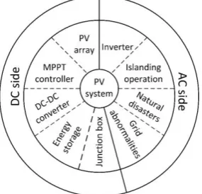
Faults in PV systems are divided on the DC side and AC side faults, figure 1 shows this category. As we see in fig. 1, DC errors occur on DC power generation parts and AC faults occur on DC to AC transform parts and power
Click here, type the title of your paper, Capitalize first letter of each words
First Author
a, Second Author
b,*aFirst affiliation, Address, City and Postcode, Country
bSecond affiliation, Address, City and Postcode, Country
Journal of Solar Energy Research (JSER)
Journal homepage: jser.ut.ac.ir
RTICLE INFO Received:
Received in revised form: Accepted:
Available online:
Keywords: Type 3-6 keywords here,
separated by semicolons ;
A Comprehensive Review and Performance Evaluation in Solar (PV)
Systems Fault Classification and Fault Detection Techniques
Navid Ghaffarzadeh
a*, Ahmad Azadian
ba,,b Faculty of Technical and Engineering, Imam Khomeini International University, Qazvin, Iran
A B S T R A C T
The renewable energy industry is growing faster than ever before and in particular solar systems have significantly expanded. Abnormal conditions lead to a reduction in the maximum available power from solar (photovoltaic) systems. Thus, it is necessary to identification, detection, and monitoring of various faults in the PV system that they are the key factors to increase the efficiency, reliability, and lifetime of these systems. Up to now, faults on PV components and systems have been identified; some of them have physical damage on PV systems and some of them are electrical faults that occur on the DC side or AC side of the PV system. Here, the faults will be divided into groups based on their location of occurrence. This paper provides a comprehensive review of almost all PV system faults and fault detection techniques of PV system proposed in recent literature.
ARTICLE INFO
Received: 16 September 2019 Received in revised form: Accepted: 7 December 2019 Available online: 8 December 2019
Keywords:
253 transmission elements. The paper is organized as the next: section 2 provides a brief overview of DC faults on PV systems. Section 3 presents various AC faults on PV systems. Different techniques of faults detection in a PV system are presented in Section 4. Finally, section 5 includes a summary and conclusion of this Work.
Figure 1. Classification of faults in DC and AC side of PV system
2. DC Side Faults
The various faults that occur in the DC side of a photovoltaic system have different characteristics, especially low fault current errors which will make it difficult to detect errors in these situations.
2.1. PV Array Faults
The power of a photovoltaic array is obtained from the sum of the output power of individual modules. During the normal operation cycle, the output power of the array is very close to the predicted value. Some factors reduce the output power of photovoltaic arrays and any factor that reduces the output is called "fault". Faults may be permanent or temporary. These factors occur on PV arrays and will have destructive effects on their longevity and efficiency [8-9].
Figure 2. Classification of PV arrays faults of PV system
2.1.1. Mismatch Faults
If the solar cell, module, and array's electrical parameters change from their initial state the mismatches faults will occur. The effects of these faults are the loss of large power and irreversible damages [1]. Mismatch faults can either be permanent or temporary [10-17].
Temporary
Partial shading
This is a fault when a transitory shadow is formed on the module (e.g. by the cloud) which results in formation of hotspots in the shaded module.
Snow covering
This fault occurs due to the weather conditions and geographical location of the system installation.
Dust/bird dropping/leaves
Dust, bird dropping and leaves may be on the top of the solar module.
Irradiance distribution
During the daytime, sunlight reaches the PV module with different radiation intensity.
Permanent
Hot spot
When solar cells operate in the opposite bias and destroy the power instead of producing, the hotspot fault occurs. Factors like shading, bypass diode fault, and mismatch between electrical characteristics are the creation of hotspot.
Soldering
This type of fault results in careless manual soldering and breaks the cells.
Hard shading
The appearance of permanent shadows of solids such as buildings on the modules will reduce the output voltage of the system.
Microcracks
At any time of cell life, cell cracking can occur. Things like Wafer slicing, cell production, stringing and other embedded are the cause of cracks. The installation process is one of the most important of these factors.
Degradation of modules
The first reason is the regression of adhesive material between glass and cells. The material color change from white to yellow and sometimes then to brown results in decreasing the light reaching the solar cells and hence reducing the generated power. The second reason is called delamination, which results in having gaps between different subsequent layers of the PV module where the adherence is lost. The delamination cases reduction in the generated power due to the light reflection increase as well as water penetration inside the module. The interconnect degradation affects both shunt and series resistance whereas contact degradation can increase the series resistance.
Potential induced degradation
This type of faults only occurs in crystalline silicon modules and results in a gradual decline in module performance. It is caused by stray currents in most ungrounded PV systems; the PV modules with a positive or negative voltage to the ground are exposed to PID. The potential included degradation mostly occurs at the negative voltage concerning the ground potential and is accelerated by high system voltages, high temperatures, and high humidity.
Light induced power degradation
254
Glass breakage
Solar cell glass can be damaged for some reason, such as poor packaging (transportation), installation and hail or stone collision.
Delamination
When moisture penetrates the solar cell's interior, delamination occurs and this reduces the active module spaces.
Discoloration
If unstable and poor quality materials are used to make cells (ethylene, vinyl, and acetate), the discoloration is occurring. For this and due to the presence of ultraviolet radiation and heat, these materials are starts to turn brown or yellow.
Interconnect breakage of bus bars
When the temperature changes repeatedly, the cell interconnections wear out.
Defects in frame
Heavy snowfall in certain areas or falling obstacles on the PV modules can damage the frame.
Cell breakage
Because of the big ribbon with a big solder bond, more local stress on the cell is possible which is lead to be more likely to break the cell.
2.1.2. Asymmetrical Fault
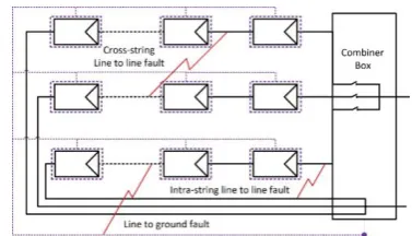
This fault may occur within the same string or between two strings as depicted in figure 3. In some situations, the line to line fault is called a bridging fault when it occurs between two modules of the same order from two different strings [18-22]. Generally, the asymmetrical fault is divided into three parts:
Line to line fault
It occurs when the unintentional connection between two nodes of the PV array.
Line to ground fault
It occurs when one conductor drops to the ground or comes in contact with the neutral conductor.
Bridging fault
Connection resistance between PV modules or cabling.
A line to line fault is an accidental low resistance connection established between two points of different potential in an electric network or system. In PV systems, a line to line fault is usually defined as a short circuit fault among PV modules or array cables with different potential. The line to line faults in PV arrays may be caused by the following reasons; I- Insulation failure of cables, i.e. an animal chewing through cable insulation.
II-Incidental short circuit between current-carrying conductors, i.e. a nail driven through unprotected wirings.
III- Line-line faults within the DC junction box, caused by mechanical damage, water ingress or corrosion.
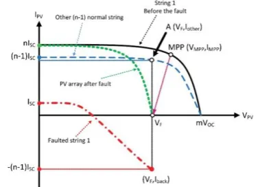
I-V characteristics in fig. 4 can be used for current flow analysis, where VOC is the open-circuit voltage of one
PV module. Before the fault, the whole PV array is working at MPP (VMPP, IMPP). After the fault, the array’s operating point drops vertically to (VF, Iarray), where VF could be still equal to VMPP. The other (n-1) normal strings will work at (VF, Iother). The faulted String 1 will work at
(VF, Iback) in its fourth quadrant of I-V characteristics as a load.
Figure 3. Examples of different asymmetrical faults in a PV array
Figure 4. I-V characteristics of the PV array during a line to line fault
2.1.3. Ground Fault
Typically, a PV array has several exposed NCC metals or conducting parts (module frames, mounting racks, metal enclosures, distribution panels, the chassis of endues appliances and power converters). These conductors do not carry any current during normal operation. However, there is a potential risk of electric shock hazard from these exposed NCC conductors when an electrical connection is established between the CCCs and NCC conductors due to a fault (for example corrosion, loss or melting of insulation, wire cutoff, and wrong wiring). Therefore, all of these NCC conductors are connected to the ground or earth through a conductor termed an “equipment grounding conductor” [6].
A PV array ground fault is happening in an electrical pathway between one or more PV array conductors and earth ground. Such faults are usually the result of mechanical, electrical, or chemical degradation of photovoltaic (PV) components or mistakes made during installation [18-26]. A Ground fault is the most common fault in PV and may be caused by the following reasons:
I-Insulation failure of cables, i.e. a rodent animal chewing through cable insulation and causing a ground fault.
255 In the worst case of a ground-fault, the ground fault current could reach as high as nISC. In this scenario, the other (n-1) normal strings have an approximate total current (n-1) ISC back feeding into String 1. Meanwhile, the modules below the ground fault point F in String one are flowing ISC into the F point.
The fault scenario could be explained with the help of
I-V characteristics analysis in fig.5, in which VOC is the open-circuit voltage of one PV module. Before the fault, the PV array is working at MPP with operating voltage
VMPP and operating current IMPP. At the moment of the ground fault, the PV array’s configuration and I-V
characteristics are changed suddenly. Meanwhile, the operating voltage at VMPP is dropping to VF immediately. Since VF is the open-circuit voltage of the faulted array, the array becomes open circuit and there is no current feeding into the PV inverter. However, the current of each string inside the PV array is not zero. For normal strings, their operating point is at A (VF,Iother) point. Notice that the operating voltage VF is close to the knee of their I-V characteristics. Therefore, each string is providing the current close to ISC. In other words, Iother (in A point) is close to (n-1)Isc. Iother has no path to go but to back feed
into String 1. As a result, Iback at String 1 becomes
(n-1)Isc, flowing into the ground fault point F.
Indeed, the ground fault is an unintentional low impedance path among one of the current-carrying conductor and the ground. There is a category in this area:
Upperground
An unintentional low impedance path between the CCC of the last two modules in a PV string and the ground.
Lower ground
An unintentional low impedance path between the CCC of the second and third modules in a PV string and the ground with large back-feed current.
Figure 5. I-V characteristics of the PV array during a ground fault
2.1.4. Arc Fault
Since the modern PV systems can have complex structures with a great number of electrical contacts, there is a significant risk of dangerous situations initiated by the occurrence of an electric arc. Due to the nature of PV modules and design of the PV systems, there could be thousands of connectors and a significant amount of cables in a PV system (cell to cell, cell to bus bar, module to
module, bypass diode parallel to solar cells, a string to string, panel to panel). Every connecting point can create an arc fault, which extraordinarily increases the possibility of arc fault occurrence, especially the series arc fault. Furthermore, several interconnections exist for mounting safety devices. These connections are created through soldering, MC4 connectors, or screw terminals inside junction boxes. There are mainly three types of arc faults in PV system: series, parallel and ground arcs [27-31].
Series Arc Faults
Degradation in solder joints, wiring or connections inside the junction box, loosening of screws or incorrect crimping may increase the connection resistance. Increased operating temperature may result in thermal stress, leading to accelerated aging or complete disconnection.
Parallel Arc Fault
Parallel arc faults can result from insulation damage due to mechanical damage, aging, or wildlife as well as previous series arc-fault events. Examples of such parallel arc faults are the following: I- Intra-string parallel arc-fault:
parallel arc fault between two points on the current-carrying conductors (CCC) of the same string. II- Cross-string parallel arc-fault: parallel arc fault between two points on the current-carrying conductors of the two different strings. III- Parallel arc fault to the ground:
Parallel arc fault between one point on a current-carrying conductor and another point at ground potential.
Parallel and grounding arc fault often draw a large amount of fault current because of the sizeable different potential, which is easier to be detected by traditional protection devices. Due to the nature of PV solar cell, the series arcing fault current (lower than normal operating current level) will not be sufficient to melt the fuse or activate the overcurrent protection devices. Specifically, the series arc fault will not draw an inverse current like parallel arc fault, and the total fault current is contributed by the normal load current. Series and parallel arc faults are illustrated in figure 6. The presence of the arc fault adds additional high-frequency components to the voltage and current signals.
Figure 6. Examples of different arc faults in a PV array
2.1.5. Bypass Diode & Open Circuit Faults
256 reverse bias heating phenomenon, hot spot and module destruction. In the absence of bypass diodes, the heat in solar cells reaches high levels and this may cause problems like hotspots which lead to browning, burn marks, and fire in worst cases. The V-I and P-V characteristics of a PV cell change and drop in the presence of the shadow and when there are no bypass diodes the open-circuit voltage and maximum power of the array reduced sharply [32-33].
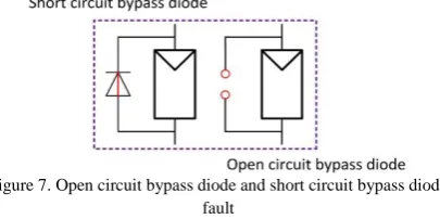
Inverted bypass diode fault in PV arrays comes from incorrect connections made by the operator. Short circuit fault originated from a bad connection between the solar cells or manufacturing defects and Open circuit fault that usually occurs as an aftereffect of line-line faults. Open circuit and short circuit fault in a PV cell are shown in figure 7.
Figure 7. Open circuit bypass diode and short circuit bypass diode fault
An open-circuit fault is an accidental disconnection at a normal current-carrying conductor. This type of fault occurs when a disconnection problem appears in a PV string or more [10]. Most of the disconnection problems are due to poor soldering in strings interconnections. Short circuit current and maximum power are decreased due to the open-circuit fault, while open voltage stays close to its normal value [34-35].
2.1.6. Lightening
Lightning is a normal natural phenomenon observed on earth and it is also visible from the outer environment. It is known as a deadly natural phenomenon because it may cause people to die. In general, lightning is a transient and high current electric discharge that path length is measured in kilometres. The air between the positive and negative charges in the cloud and between the cloud and the ground acts as an insulator. When the opposite charges build up enough, the insulating capacity of the air breaks down. The rapid discharge of electricity is known as lightning [36].
Although installing the PV systems in large, open and unobstructed areas because of no shading is more efficient, but these areas are more exposed to lightning. A lightning strike in such areas is causing serious damage to the PV system. This can reduce the PV system reliability and increases system repair and replacement costs. When lightning strikes a PV system it will create transient current and voltages throughout the system. The transient currents and voltages will become visible in the equipment terminals and cause insulation and dielectric failures within the solar PV electrical and electronic
components such as the PV panels, inverter, and control and communications equipment [36-39].
Heavy physical and mechanical damage is one of the destructive results caused by a lightning strike. In this situation, there are two types of damage. The first one is a direct lightning strike to photovoltaic panels and the discharge hits some surrounding device that the panel is completely destructed in this case. Very strong lightning current melts the panel frame and the semiconductor structures. This damage is visible and easily recognizable. This type is a very small case. The second type is more common, but it is difficult to identify. Due to the presence of overvoltage, the panel damage itself. The semiconductor structure is seriously damaged, but it is not visible to the naked eye.
2.2. MPPT Fault
The presence of the MPPT control system in the solar system improves the performance of the photovoltaic system, but this addition increases the probability of the system overall. MPPT increases the input power delivery from the output (PV arrays). If a fault occurs in MPPT control system, the output voltage and current adjustment may be faulty, which results in a decrease the output voltage and power. At the time of the occurrence of this type of error, the output power becomes very low [40]. Maximum power point tracking fault may have divided into two parts; the first case is the sensors and the second one is a fault that may happen in the MPPT algorithms. In maximum power point tracking algorithms voltage, current and temperature sensors are used to read and delivery the inputs of these algorithms. Sensors may break down and cannot sense the parameters. The second one is the errors occurred in MPPT block; faults in all electronic circuits such as elements, cables, etc. in the MPPT block; and the main fault is lack of proper performance of algorithms [41].
2.3. DC-DC Converter Fault
The DC-DC converter is a vital and functional element in PV system. DC-DC converters transform dc power from a voltage level to another level. The presence of the converter is essential for performing the maximum power point tracking operations and this is done with calculates the appropriate IGBT control. Maximum power point is achieved by this algorithm. Factors such as different environmental conditions, transient state, high load, thermal/power cycles, Production defects, etc. can affect semiconductor performance [43]. The most fragile components in DC-DC converters based on reports are power switching devices, capacitors, gate driver circuits, connectors, inductors, resistors, and other devices. Also, 66% of PV system faults occur in the power processing stage [46].
257 cycles, Production defects, etc. are the most vulnerable components. [43]. According to available reports, fragile components in DC-DC converters according to failure rates is power switching devices, capacitors, gate driver circuits, connectors, inductors, resistors, and other devices. It is reported that 66% of errors occur in the power processing stages of PV systems [46]. The lifetime of power processing components and elements relative to PV arrays are too short [42-49].
Assembly Failure
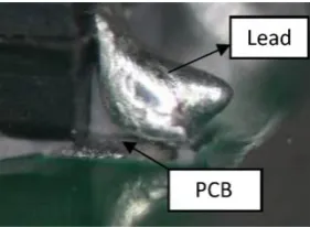
Recently there have been many types of research in DC-DC converter on wire bonding failure. Initial electrical investigations have shown that there was no short circuit between the input and output terminals (the output voltage was 0v). As shown in Figure 8, after the encapsulate material was de capsulated, poor wetting of the solder to the PCB pad was found in a solder joint of a transistor in the +12V control circuit. The main reason for this was may have been the contamination of the PCB which led to its poor solder ability. Increasing the accuracy of the soldering process can solve poor wetting.
Figure 8. Poor wetting of solder to PCB pad
The solder migration between two solder joints in the primary winding of the transformer in another case is shown in Fig. 9. The electrical short circuit of two solder joints is caused by the metal migration. The causes of electro-migration failure can be attributed to flux residue from soldering process, condensed moisture, and voltage bias. The two most important factors that prevent this fault are the cleaning of flux residue and controlling of moisture.
Figure 9. Solder migration between two solder joints
Components Failure
The first case is that the resistance between some of the input ports of the failed DC / DC converter was low, where it showed short electrical evidence. After de
capsulation, it was seen that the MOS devices were fired from the input port and the package was cracked, as shown in Figure 10. The fused copper substrate showed high-voltage arc characteristics of the source and chip discharge electrode. It was also found that the chip was burnt from the PWM in the input control circuit. So it should be concluded that the MOS and PWM chips were burned by electrical overstress and the failed components resulted in the failure of DC /DC converter.
The second case is that the filtering inductor was affirmed after a series of measurement and analysis. So between the ports there was a short connection. The enameled wires of the filtering inductor were unwrapped and inspected round and round. In figure 11 the carbonation and cracking of partial coating were identified. Separating the broken wires were disappeared the electrical short. When wires enameled by defective coating, the electrical leakage is resulted from the carbonation and cracking of coating.
Figure 10. Chips were burned by electrical overstress, (a) MOS chip (b) PWM chip
Figure 11. Views of cross section of terminal electrode Views of carbonation of enameled wires
2.4. Energy Storage Fault
258
Physical Damage
If the battery is stored, handled or fitted inaccurate if the connectors leads are fixed onto the terminals, leads are fastened incorrectly, the battery will have damage to casing and terminals.
Sulphation
If a battery is allowed to stand in a discharged state for some time, a chemical reaction takes place which will permanently impair the performance and life of the battery, this process is named “sulphation”.
Wear and Tear
As the battery is cycled; it means charged and discharged, the active materials are moving inside the battery plates to release the stored electricity in the battery. Every time the battery is charged and discharged a small amount of active material is permanently lost from the plates.
Deep cycling
As previews item, every time a battery is charged and discharge cycled a small amount of material is lost. If a battery is exposed to deep discharging (greater than 35%) and rapid charging the process is accelerated.
Additionally, if the recharge does not recover the discharge cycle in full, the battery will exhibit loss of performance and concentration of the acid can occur between plates which can lead to corrosion and loss of performance.
Overcharging
If the alternator regulator does not work accuracy, or control circuit of alternator voltage fails, then the battery can be subjected to an excessive charge.
Undercharging
If the battery does not have enough charge to return it to a full state of charge, this will slowly cause sulphation. If the battery is being used only occasionally for short usages this fault may occur.
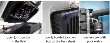
Figure 12. Examples of junction box failures
2.5. Junction Box Failures
Junction boxes are required in all DC parts of the photovoltaic system to connect the components and elements. For this reason, this type of fault may occur in any part of the system. The main task of these boxes is to protect the wires that are connected from their strings to an external terminal. The faults that may occur for these boxes are: poor fixation of the junction box to the back sheet, moisture penetration, corrosion of connections, poor wiring leading to internal arcing, poor mounting or
because of thermal degradation [52]. Some examples of these failures are presented in Fig. 12.
3. AC Side Faults
3.1. Inverter Fault
Defective inverters can lead to significant production losses. Whilst the modules are responsible for generating electricity, the inverters are responsible for converting and feeding the power to the grid. Good performance by inverters is therefore very important [53-58]. We have listed below five common problems with inverters:
Faulty installation of the inverters
A possibly obvious, yet very common problem with inverters is that they have been installed incorrectly. This can range from physically misconnecting them to incorrect programming of the inverters. In this context, the installers' expertise is very important. Correct installation can then be checked at the handover of the solar park or during the start-up phase of the project by carrying out several tests, such as yield test, remote activation and deactivation and regulation of the reactive power.
Overheating
Inverters are made up of electronic components, and therefore sensitive to temperatures. High temperatures will lead to a significant reduction in production, and can even result in a production stop if the maximum operating temperature is reached. An assessment must, therefore, be made as early as the design stage to determine whether the proposed cooling technology is adequate and whether it has sufficient capacity. For example, it is very important that the switch cabinet and the building housing the inverter(s) are well ventilated. Alongside an assessment of the initial design, it is highly advisable to regularly check the cooling during the operational period and to establish that the cooling or ventilation system is operating correctly. In addition to this, many steps can be taken to prevent excessively high temperatures, such as installing and cleaning dust filters, removing undergrowth that impedes airflow, etc.
Isolation fault
259
Inverter does not restart after a grid fault
An inverter must be able to restart itself after a grid fault (if there are no other faults). For example, voltage peaks which occur during sudden deactivation could trigger cut-outs in the system. If the inverter does not restart itself, a service team will then have to come on-site to restart the system. This will lead to unnecessary production loss. It is therefore not just the brand of the inverter that is important, but also the quality of the components used as well as the use of a good 24/7 monitoring system to detect faults as quickly as possible. If this is not organized properly, all PV modules connected to the inverter will be unable to deliver power until the fault has been discovered and an engineer has rectified the fault. This is a problem that particularly occurs in areas where the grid connection is not always stable.
The MPPT module
Modern inverters operate based on the MPPT technique. MPPT stands for Maximum Power Point Tracking, and this module has been developed to maximize the performance of inverters. Because of the scale of current larger PV systems, multiple rows of PV modules are connected in series (called “strings”). The strings are then jointly connected to an inverter. However, not all strings produce the same amount of power as a result of many factors such as shading, different positioning, fault in a panel, etc. The strings deliver different voltages, and the difference between the strings in this regard varies continuously. The algorithm in the MMPT module is designed in such a way that the inverter always uses the most optimum supply voltage despite these differences in strings. This always maximizes the amount of electricity produced. It is therefore important that the working order of the MPPT module is established, and that it is working well. This can be done by carrying out some performance tests during the start-up of the solar park. Establishing the correct operation of the MPPT module is also necessary to be able to make a good comparison between the actual yield and the guaranteed yield according to the manufacturer.
3.2. Grid Abnormalities
A failure (or a fault) in a grid-connected PV system is defined as an effect that decreases the performance of the system (decreased output power). On this side of the PV system, two types of faults can be identified: total blackout and grid outage (lightning and unbalanced voltage) [41]. There are two reasons that ordinary grid-tied solar will not work during a grid failure. The first is a technical reason and the second is a safety and regulatory issue. First and foremost is the technical reason. The electronics that control a solar electric system constantly adjust voltage and current to keep the panels operating at their most efficient and powerful operating point through a range of varying sunlight conditions. To do this, the system needs to be able to produce quantities of power that are not dependent on how much your house is using at the time. In a grid connected system, that excess power is put back onto the grid for others to use. The second reason that solar shuts down during a blackout is safety. During a
power outage, the power utility sends out repair crews to find and fix the points of failure. The linemen and women can be jeopardized if there is a local power generator (like a solar array) leaking power onto the grid lines. Therefore, utility rules mandate that in the event of a power outage, solar arrays must automatically shut down. Solar systems have detectors that sense whether power is coming across the grid, and whenever grid power is down, they automatically shut down too [59-60].
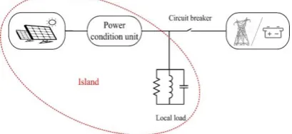
3.3. Islanding Operation
Islanding occurs when a PV system feeds power into a section of the utility system which has been isolated from the utility voltage source. Consider the configuration shown in Figure 13. If the switch were opened, under certain conditions the PV PCU can continue to energize the isolated section of the grid and supply power to the local load. This is islanding, and the isolated section of the utility being powered by the PV system is referred to as an island of supply or simply an island. Islanding mode of operation causes the utility grid to be disconnected from the DG to prevent any damage in the system. Under this condition, the grid is no longer servicing as a solid voltage and frequency reference. This phenomenon occurs when utility suffers from unpredictable interruption of abnormality, such as voltage shut-down, short-circuit or equipment failure [61-63].
There are two types of islanding modes, namely the intentional (planned) and the unintentional (unplanned) islanding [63]. The purpose of intentional islanding is to sectionalize the utility system to create a power ‘island’ during an occurrence of disturbance. This is a common scenario, especially for maintenance purposes. Typically, intentional islanding is harmless to the power system because the problem can be solved during or after the grid disconnection. However, unintentional islanding can create a severe impact on power system stability due to the loss of grid synchronization. Consequently, this causes the DG to be out of the voltage and frequency references. This may damage the electrical devices and systems equipment in the islanded section [62-64].
Figure 13. An overview of islanding mode in a grid connected PV system
3.4. Sudden Natural Disasters
260 system occurred. As a result of these disturbances, instant frequency and voltage increased and a large blackout happened on the Power System [65].
4. Fault Detection
Failure detection techniques are different diagnostic methods which are used to identify PV systems faults. In other words, classifications of failure techniques include different methods that are used to indicate the type of failure that occurs within a PV system. Therefore, power losses caused by faults could be minimized by notifying the operator about the most probable failure sources allowing them to take corrective actions.
Several fault detection methods are presented in this article. A reliable fault detection method or algorithm should have the following features: 1) Ability to detect multiple faults without interruption in power generation, 2) Capability to distinguish and localize faults, 3) Economical and flexible; such that integration with existing PV systems is easy, 4) Having a simple structure and 5) Have global application regardless of size and type of PV system [10].
Fault detection techniques can be globally classified into two main categories [66]: Visual and thermal methods, which can be used for detecting discoloration, browning, surface soiling, hot spot, breaking, and delamination. Visual inspection is the first step in deciding whether further tests should conduct on the PV module. Electrical methods that can be used for detecting and diagnosing faulty PVM, strings, and arrays including arc fault, grounding fault, diodes fault, etc. [67-69].
Most electrical-based fault detection technique methods rely on some type of PVS model to detect various types of faults. In this section, the performance of all recent fault detection technologies proposed in the literature is critically reviewed [10, 11, 60, and 70]. The algorithms for identifying faults in the photovoltaic system and for islanding are discussed below. Reviews of past articles in fault detection field is presented in Table 1 to 6.
4.1. PV System Fault Detection Techniques
In general, PV fault detection techniques allow identifying the type & location of different failures of PV
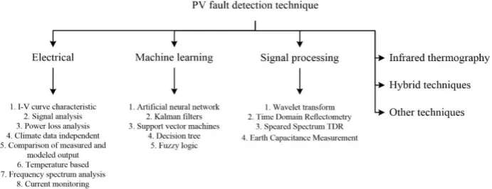
systems. Such techniques should be robust to increase system reliability and lifetime and provide safe operation. Also, the techniques should be fast in detecting evolving faults to avoid consequences and further failures. Different fault detection techniques are summarized in Fig. 14.
4.1.1. Electrical Characterization
Over time many diagnostic methods are developed to detect faults in photovoltaic systems which are based on the analysis of electrical parameters. In this fault detection category direct electrical, irradiance and meteorological measurements and also make use of the I-V characteristic curve data, signal generators, circuit and simulation models are required. Important and valuable information from PV modules can be obtained from the I-V curve because it allows checking most of the operation points of the module. Between thermal methods, visual methods, and electrical methods for failure detection, the last stated method is the most appropriate to integrate into a power conditioner. In the following, fault detection algorithms based on electrical characteristics measurements and related articles are expressed.
I-V curve
In this method, by using electrical measurements, the signals required from the cell or photovoltaic module are measured; Voltage, current, temperature, etc.
Signal analysis
Faults in the photovoltaic system can be detected by signal processing of different signals. Due to the high applicability of this algorithm, it will be examined separately.
Power loss analysis
This technique is based on the analysis of power losses in the PV system. For fault detection, power losses are calculated by comparing the monitored data with simulated results.
Climatic data-independent
261 (such as temperature, irradiance, humidity, wind speed, etc.).
Measured and modeled PV system outputs comparison
Measurement of the differences between measured and modeled the outputs of the photovoltaic system is used for fault detection.
Temperature and heat-based models
When a fault occurs in the photovoltaic modules, heat is generated and the temperature of the PV cell is increased. Temperature and heat measuring devices can help to identify the fault.
4.1.2. Machine Learning (Numerical) Techniques
Machine learning (ML) is a kind of data analysis which uses algorithms that learn from data via a process called training. Over the years, ML algorithms have been applied successfully in many applications in areas such as natural language processing, computer vision, and healthcare. Inspired by these examples, ML applications have now been extended to PV systems fault detection and diagnosis. The remainder of this section provides a review of PV fault detection diagnosis systems based on ML algorithms.In the past years' machine learning algorithms, such as ANN, Kalman filters, SVM, DT, FL, and expert systems, are becoming very popular for fault detection. Machine learning-based algorithms are trained to learn the relationship between input and output parameters of a PV system. This training data experimentally or with the help of accurate PV models can be collected. Nevertheless, abnormal data during a fault is also required for accurate training and prediction. When an accurate and trained model is created, it can easily identify faulty states by simple error evaluations. Machine learning techniques in fault detection helps to overcome the difficulty of defining thresholds and aids in accurate detection and classification of faults. According to the stated cases, this method also suffers from the following disadvantages. The accuracy depends on the quality of the data training; The difficulty of data collecting; Since the accuracy of the identification depends on the entire PV panel, training machine learning algorithms using PV models is not reliable and training data is not available globally and varies according to the type, size, and location of the PV system.
This table includes papers which had worked on various detection tools based on machine learning techniques for the identification of failures at the PV system level.
4.1.3. Signal Processing Approaches
To monitor the performance of photovoltaic power plants, the Statistical signal processing approaches are used to detect the faults to accurate detecting failures mainly on the DC side of the system. Signal processing methods are mainly based on the analysis of the waveform signals; for example, Time Domain Reflectometry (TDR), Speared Spectrum TDR (SSTDR) and Earth Capacitance Measurement (ECM) are used to detect and localize faulty
PV modules. Time domain reflectometry is a measurement technique used to determine the characteristic of electrical lines by observing reflected waveforms; and spread spectrum time domain reflectometry is a measurement technique to identify faults, usually in electrical wires, by observing reflected spread spectrum signals. Of the most common implementations of statistical analysis, methods are defined thresholds for each monitored parameter and compare the measured value to threshold limits to decide on normal or fault condition.
4.1.4. Infrared Thermography
Infrared thermography measures the radiation emitted by the surface of anybody in the infrared wavelength spectrum between 1.4 – 15µm. The infrared thermography employed for PV applications usually detects wavelengths in the mid-wavelength range of 7 – 14 µm, which is a trade-off between costs, availability and measuring conditions of IR sensors. This method is based on the concept of localized heat generation because of Joule heating effect due to shunted cells, poor contacts, short circuits, etc. IRT can be used for the detection of a great number of defects in PV cells, modules and strings since the majority of the defects have an impact on their thermal behavior. Short circuit, shunted cells, shadowing, potential induced degradation (PID), substring open circuit, defective bypass diode, internal short circuit, open circuit module and failed system connection are the fault that this method can detect. IRT is a non-destructive and contactless method that can be performed under steady-state operating conditions. Furthermore, IRT can provide information about the exact physical location of an occurring fault, which allows for
posterior electrical diagnosis of the problem. Traditionally, IRT inspections for PV applications are performed with handheld IR cameras on the ground or on lifting platform to increase the coverage. This procedure is dependent on human labor and competence and very time-consuming and labor-intensive. As a result, the monitoring accuracy is prone to human error and the uncertainty of the method increased. To increase the cost-effectiveness and employ IRT for large-scale PV plants or roof-mounted PV systems with limited access, IRT can be combined with aerial technologies like unmanned aerial vehicle (UAV). The recent developments in the field of UAV made this technology available for civil activities like disaster relief, energy equipment monitoring, environmental control, forest inspection or mine monitoring [11-12].
262
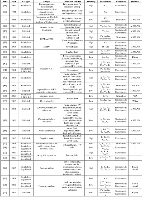
Ref's Year PV type Subject Detectable failures Accuracy Parameters Validation Software
[71] 2006 Stand alone Earth capacitance measurement
Disconnection of PV
module in a string High Vstr Experiments -
[72] 1994 Stand alone
Measure the electrical characteristics of transmission line
breakdown point, faults
and impedance change High Vstr Experiments -
[124] 2008 Stand alone
Non-parametric Kruskale Wallis (KW) and Analysis of Variance tests
Degradation status and
a system abnormality Low
PV
parameters Simulation MATLAB
[74] 2018 Grid tied
Wavelet packet transforms
Partial shading and
line-to-line faults High Varr, Iarr, Parr
Simulation &
Experiments MATLAB
[75] 2016 Grid tied Open-circuit and
inverter faults High Varr, Iarr
Simulation &
Experiments MATLAB
[76] 2009 Grid tied
ECM and TDR
Degradation of connectors and disconnections between
PV modules
High PV module
characteristic Simulation MATLAB
[77] 2008 Stand alone High Vstr Experiments -
[78] 2018 Stand alone SSTDR Ground faults High SSTDR Simulation &
Experiments MATLAB
[73] 2019 Stand alone
Measure V & I
Shading fault High parameters Ig, Tm, PV Simulation & Experiments MATLAB
[79] 2012 Stand alone Bypassed substrings,
fractured and soldering Low Vmp, Imp
Simulation &
Experiments PSpice
[80] 2014 Grid tied
Automatic fault detection in grid connected PV system
High Ig, Tm, Varr, Parr, Vac, Pac
Simulation &
Experiments MATLAB
[81] 2011 Stand alone
& Grid tied Degradation Low
PV module
parameters Experiments -
[82] 2015 Stand alone
Partial shading, PV module, short-circuit
faults, bypass diode and connection faults
High Ig, Tm, Varr, Parr, Iarr, Pac
Simulation &
Experiments MATLAB
[83] 2015 Stand alone Open & short circuit
faults High
Ig, Tm, Varr,
Parr, Iarr, Simulation LabVIEW
[84] 2013 Grid tied captured losses in PV, current & voltage ratios
Fault diagnosis in grid
connected PV system Low
Ig, Tm, Varr, Parr, Vac, Pac
Simulation &
Experiments MATLAB
[85] 2015 Stand alone
& Grid tied Empirical model
Inverter fault
Low Ig, Tm Simulation ANN
[86] 2016 Grid tied Physical model Low Varr, Iarr, Vac, Iac
Simulation &
Experiments PVSyst
[80] 2014 Grid tied Absolute performance ratio error
Partial shading, PV module faults, faulty string, inverter and
MPPT faults
High Ig, Tm, Varr, Parr, Vac, Pac
Simulation &
Experiments MATLAB
[87] 2016 Grid tied Current and voltage indicators
Partial shading, bypassed PV module, open and short circuit faults, and inverter
disconnection
Low Ig, Tm, Varr, Parr, Iarr
Simulation &
Experiments MATLAB
[88] 2007 Grid tied Profile comparison
Array fault, degradation, MPPT fault and grid outage
Low Ig, Id It, Tm, Ta, Pac, Parr
Simulation &
Experiments MATLAB
[89] 2010 Grid tied Empirical model
Partial shading, BOS faults, inverter and
MPPT faults
High Ig, Tm, Ta,
Parr, Pac Experiments -
[90] 2013 Stand alone thermal behaviour of PV cells resulting from
electrical faults
Different types of PV cells
Low Ig, Tm, Voc, Isc Simulation MATLAB
[91] 2012 Stand alone
& grid tied Low
Tm, Ta, Sw,
Varr, Iarr Experiments -
[92] 2009 Stand alone & grid tied
Array leakage current Inverter faults
High Ta, Rs, Rp,
Voc, Vl Experiments -
[93] 2010 Stand alone
& grid tied Low
Ig, Ta, Tm, Rs,
Il Experiments -
[94] 2013 Stand alone
& grid tied Fuse open/close
Effect of humidity, resistance of the grounding conductor, ambient temperature, electromagnetic interference, and salt
High Ig, Tm, Rs, Zarr, Voc, Isc
Simulation & Experiments
Sandia model
[95] 2011 Stand alone & grid tied
Frequency analysis
Irradiance variation level, partial shading, noise from the inverter
and arcing
Low V, f Experiments -
[96] 2012 Stand alone
& grid tied Low
Ig, Ta, Vnoise, Inoise, Vstr, Istr,
f
Simulation & Experiments
Sandia model
[97] 2012 Grid tied Low
PV module characteristic
s
Simulation &
Experiments PSpice
263
4.1.5. Hybrid Detection Techniques
Typically, hybrid algorithms combine two fault detection algorithms to identify faults. The advantages of using hybrid algorithms for detecting a fault in photovoltaic systems can be noted: increasing the accuracy of fault detection, increasing the number of fault detection, less complexity of computing and between the various effect of the fault, the fault exactly specifies. In the table below, the papers presented in this field will be examined.
4.1.6. Other Techniques
This subsection expands the review of the advanced fault detection and diagnosis techniques to include studies that have been reported in the literature but do not fall into any of the categories already discussed
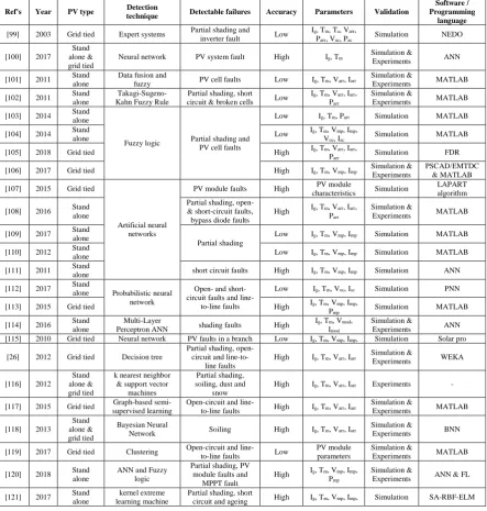
Ref's Year PV type Detection
technique Detectable failures Accuracy Parameters Validation
Software / Programming
language
[99] 2003 Grid tied Expert systems Partial shading and
inverter fault Low
Ig, Tm, Ta, Varr,
Parr, Vac, Pac Simulation NEDO
[100] 2017
Stand alone & grid tied
Neural network PV system fault High Ig, Tm Simulation &
Experiments ANN
[101] 2011 Stand alone
Data fusion and
fuzzy PV cell faults Low Ig, Tm, Varr, Iarr
Simulation &
Experiments MATLAB
[102] 2011 Stand alone
Takagi-Sugeno-Kahn Fuzzy Rule
Partial shading, short circuit & broken cells Low
Ig, Tm, Varr, Iarr, Parr
Simulation &
Experiments MATLAB
[103] 2014 Stand alone
Fuzzy logic Partial shading and PV cell faults
Low Ig, Tm, Parr Simulation MATLAB
[104] 2014 Stand
alone Low
Ig, Tm, Vmp, Imp,
Voc, Isc Simulation MATLAB
[105] 2018 Grid tied High Ig, Tm, Varr, Iarr, Parr Simulation FDR
[106] 2017 Grid tied High Ig, Tm, Vmp, Imp Simulation & Experiments
PSCAD/EMTDC & MATLAB
[107] 2015 Grid tied
Artificial neural networks
PV module faults High PV module
characteristics Simulation
LAPART algorithm
[108] 2016 Stand alone
Partial shading, open- & short-circuit faults, bypass diode faults
High Ig, Tm, Varr, Iarr, Parr
Simulation &
Experiments MATLAB
[109] 2017 Stand alone
Partial shading
Low Ig, Tm, Vmp, Imp Simulation MATLAB
[110] 2012 Stand
alone Low Ig, Tm, Vmp, Imp Simulation MATLAB
[111] 2011 Stand
alone short circuit faults High Ig, Tm, Vmp, Imp Simulation ANN
[112] 2017 Stand
alone Probabilistic neural network
Open- and short-circuit faults and
line-to-line faults
Low Ig, Tm, Voc, Isc Simulation PNN
[113] 2015 Grid tied High Ig, Tm, Vmp, Imp,
Pmp Simulation MATLAB
[114] 2016 Stand alone
Multi-Layer
Perceptron ANN shading faults High
Ig, Tm, Vmod, Imod
Simulation &
Experiments ANN [115] 2010 Grid tied Neural network PV faults in a branch Low Ig, Tm, Vmp, Imp, Simulation Solar pro
[26] 2012 Grid tied Decision tree
Partial shading, open-circuit and
line-to-line faults
High Ig, Tm, Varr, Iarr Simulation &
Experiments WEKA
[116] 2012
Stand alone & grid tied
k nearest neighbor & support vector
machines
Partial shading, soiling, dust and
snow
High Ig, Tm, Varr, Iarr Experiments -
[117] 2015 Grid tied Graph-based semi-supervised learning
Open-circuit and
line-to-line faults High Ig, Tm, Varr, Iarr
Simulation &
Experiments MATLAB
[118] 2013
Stand alone & grid tied
Bayesian Neural
Network Soiling High Ig, Tm, Varr, Iarr
Simulation &
Experiments BNN
[119] 2017 Grid tied Clustering Open-circuit and line-to-line faults Low
PV module parameters
Simulation &
Experiments MATLAB
[120] 2018 Stand alone
ANN and Fuzzy logic
Partial shading, PV module faults and
MPPT fault
High Ig, Tm, Vmp, Imp, Pmp
Simulation &
Experiments ANN & FL
[121] 2017 Stand alone
kernel extreme learning machine
Partial shading, short
circuit and ageing High Ig, Tm, Vmp, Imp, Simulation SA-RBF-ELM
264
Ref's Year PV type Type Detectable failures Accuracy Parameters Validation
Software / Programming
language
[122] 2011 Grid tied Wavelet transform
Inverter failures in PV systems
High Ig, Tm, Vmod, Imod
Simulation &
Experiments PSCAD
[123] 2015 Grid tied
Probability distribution – TL –Physical and regression models
High Ig, Tm, Varr,
Iarr, Vmod, Imod Experiments -
[124] 2008 Stand
alone ANOVA, Kruskal-Wallis Low
PV
parameters Simulation MATLAB
[125] 2017 Grid tied
Exponentially Weighted Moving Average
Partial shading, open- and short-circuit
faults
Low Ig, Tm, Vmp,
Imp Simulation
PSIM & MATLAB
[126] 2018 Grid tied High Ig, Tm, Vmp,
Imp, Pmp Simulation
PSIM & MATLAB
[127] 2016 Grid tied
T-test
PV module faults, faulty string, bypass
diode faults, MPPT fault
High Ig, Tm, Varr, Iarr
Simulation &
Experiments LabVIEW
[128] 2017 Grid tied Low Ig, Tm, Vmp,
Imp, Pmp
Simulation &
Experiments MATLAB
[129] 2017 Grid tied High Ig, Tm, Vmp,
Imp, Pmp
Simulation &
Experiments MATLAB
[26] 2012 Grid tied
Outlier rules
Partial shading, open-circuit, line-to-line and ground faults and
degradation
High Ig, Tm, Varr, Iarr
Simulation &
Experiments WEKA
[130] 2014 Grid tied Line-to-line faults High Varr, Iarr, Istr Simulation &
Experiments MATLAB
[131] 2013 Stand alone
wavelet transform for arc fault detection
Arc faults
Low PV module parameters
Simulation &
Experiments MATLAB
[132] 2012 Stand alone
minimum covariance
determinant estimator High
Ig, Tm, Varr,
Iarr, Vmod, Imod Simulation MATLAB
[133] 2011
Stand alone & grid tied
Arc fault circuit
interrupter requirements Low Varc, Iarc, Vstr Experiments -
[134] 2009 Grid tied ECM and TDR Disconnection in strings, increase series resistance and
PVM degradation
High Vstr Experiments -
[135] 2008 Stand alone ECM High
Oscilloscope & pulse generator
Experiments -
Table 4. Review on hybrid detection method
Ref's Year PV
type Subject Hybridization Accuracy Parameters Validation
Software / Programming
language
[138] 2013 Stand alone
Proposed a novel PV model by incorporating an energy
balance equation to the conventional cell model to
relate the electrical and thermal chr. of PV
ITH technique and its accuracy is utilized to measure the temperature
of panels for achieving reliable predictions from
PV model
High Ig, Ta, Sw, Vmod, Imod
Simulation &
Experiments MATLAB
[108] 2016 Stand alone
For diagnosing faults characterized by different
fault signatures, conventional RDM approach was utilized and For the faults characterized by the same combination of fault signatures, MLT based
on ANN was used for diagnosis
Combined MLT and
RDM High
Ig, Tm, Varr, Iarr, Parr
Simulation &
Experiments MATLAB
[139] 2016 Stand alone
Reverse DC bias voltage was injected into the PV string to identify open circuits in the bypass path
while hotspots were detected
Using the thermal images obtained via infrared thermography
technique
High
Ig, Tm, PV module parameters
Simulation -
[140] 2017 Grid
tied Identifying line to line faults
A two stage SVM and
MSD was utilized Low Ig, Tm
Simulation & Experiments
PSCAD/EMTDC & MATLAB
[104] 2014 Stand alone
Solve the undetectable and unlearned faults in current and in voltage during the utilization in conventional
overcurrent and in overvoltage protection
devices
Neuro and fuzzy
algorithms Low
Ig, Tm, Vmp,
Imp, Voc, Isc Simulation MATLAB
265
4.2.Islanding Detection Methods
Many various techniques have been introduced to detect islanding faults. These techniques are generally classified into two main groups: (a) local schemes and (b) remote schemes. A schematic representation of various IdMs is shown in Figure 15, which are being studied and investigated for years. Due to advances in signal processing, intelligent tools and grid integration technologies, the fault detection algorithms performed better. In the following, the algorithms and related articles are discussed [152-157].
4.2.1. Active methods
In local island fault detection methods, perform fault detection by using measurements of the system parameters at the DG (PV) site such as voltage, frequency, current, and harmonic distortion. Active algorithms operate by injection a small perturbing signal into the Distributed Generation (PV) output. In under islanding condition, external signal injection causes significant changes in system parameters. But this signal injection may lead to lower power quality and the production of harmonic disturbance that reduce system performance. For this reason, it is recommended to use these algorithms in systems that are equipped with inverters.
4.2.2. Passive Methods
In Passive islanding detection algorithms, parameters like voltage, current, impedance, power, or frequency should be controlled in the terminals. When the system is not connected to the grid, these parameters change significantly. It is essential to have protective relays and sense these changes. The passive approaches do not affect power quality or grid operations. The disadvantages of these algorithms are the low fault detection speed and the large NDZ.
4.2.3. Hybrid Methods
Hybrid algorithms are created by integrating active and passive detection methods. To detect the faults with hybrid methods there are two stages of fault identification; active and passive procedure. The performance of these types of algorithms is as follows: The passive detection method is used as the primary identification, then the active detection method is implemented when the islanding is suspected by the passive method.
4.2.4. Remote (Central) Methods
This method uses technique of communication links between DG sources and the utility grid. The performance of this algorithm is efficient and its NDZ is negligible. An NDZ is also defined as a range of operational power region that is not protected by conventional protection devices [49].
Table 5. Review on other detection methods
Ref's Year PV type Subject Detectable failures Accuracy Parameters Validation
Software / Programming
language
[141] 1995 Stand alone & grid tied
Ultrasonic inspection method
Module degradation
mechanisms Low Ta Experiments -
[142] 2018 Stand alone
Based on the rate of rise of current with the
current magnitude
Detection shading effect, inverter stop, short circuit current
Low Ig, Tm, Vmp,
Imp, Voc, Isc Simulation MATLAB
[143] 2008 Stand alone Electroluminescence imaging
Non-uniform current
and poor connections Low Ig, Tm, Rg Simulation MATLAB
[144] 2012 Stand alone
Calculation of PV insulation resistance &
leakage current
Detection of leakage and insulation
current
Low Ig, Tm, Voc, Isc Simulation MATLAB
[145] 2012 Stand alone Online FDe and
tolerance technique Degradation faults High
Ig, Tm, Vmod, Imod, Vbat, Ibat
Simulation &
Experiments MATLAB
[138] 2013 Stand alone
Measure current and voltage cha. and module temperature using a thermal camera
PV module faults High Ig, Ta, Sw, Vmod, Imod
Simulation &
Experiments MATLAB
[146] 2014 Stand alone Monitors and regulates
output current DC-DC converters Low Ig, Ta, VO, IO Simulation MATLAB
[147] 2014 Grid tied Dipped the voltage Line to line fault in
grid-connected PV Low Ig, Ta, VO, IO Simulation MATLAB
[80] 2014 Grid tied
Graphically under MATLAB/GUI to display instantaneously
Fault detection in a grid connected PV
system
High Ig, Tm, Varr, Parr, Vac, Pac
Simulation &
Experiments MATLAB
[148] 2015 Stand alone & grid tied
A very fast technique based on the shape of the inductor current
DC-DC converter High Ig, Ta, Vmp,
Imp VO, IO Simulation MATLAB
[149] 2015 Grid tied Analysis of the AC
voltage patterns Inverter faults High
Ig, Tm, Varr,
Iarr, Parr Simulation MATLAB
[150] 2015 Stand alone
Use of output resistance, the reverse saturation current, the junction capacitance
Cracked PV modules High
Ig, Tm, Varr, Parr, RS, Iph,
VT
Simulation &
Experiments MATLAB
[151] 2016 Grid tied
Relies on the quantum probability model
theory
Array fault High
PV module and PV system parameters
Simulation &
266
Table 6. Review on islanding detection methods
Ref(s) Year PV type Detection technique Accuracy Validation Software /
Programming
[153] 2008 Grid tied Injection interharmonic test current for measuring the impedance
of the public grid to detect islanding situation High Simulation DFT algorithm [154] 2017 Grid tied Using phase disturbance based on grid synchronization High Simulation MATLAB
[155] 2010 Grid tied
Introduces a phase shift perturbation which leads to measurement inaccuracy, noise in response, and quantization error by
introducing an additional phase shift
High Simulation &
Experiments MATLAB
[156] 2016 Stand alone
Performance of Slip mode frequency shift islanding detection method in the presence of different inverter interface control
strategies
High Simulation &
Experiments MATLAB
[157] 2011 Grid tied Injection of a negative-sequence current through the interface
voltage-sourced converter of a distributed generation unit High
Simulation &
Experiments PSCAD/EMTDC [158] 2006 Stand alone Monitor the grid voltage/frequency by the standards Low Simulation PSCAD
[159] 2015 Stand alone
& grid tied Rate of change of frequency or power Low Simulation EMT
[160] 2011 Stand alone Monitors the phase difference between the current and the
terminal voltage High Simulation MATLAB [161] 2005 Stand alone does not lead to false tripping by selecting a trip threshold Low Simulation Signal processing
[162] 2004 Stand alone two monitoring parameters (THD of the current and voltage) High Simulation PSCAD & EMTDC [163] 2008 Grid tied threshold selection problem and high Q-factor Low Experiments - [164] 2018 Grid tied disturbances that occur in the grid passive techniques High Simulation MATLAB
[165] 2007 Stand alone hybrid technique based on the voltage unbalance and THD and
the positive feedback techniques Low Simulation MATLAB
[166] 2003 Grid tied compared the real power changes with the positive feedback
technique High
Simulation &
Experiments MATLAB
[167] 2010 Stand alone
& grid tied voltage fluctuation injection using high impedance load High Experiments - [168] 2010 Stand alone SFS and Q-f curve High Simulation MATLAB
[169] 2007 Stand alone proposed a WT technique to obtain the time localization of
signals from single-phase PV system Low Simulation MATLAB
[170] 2009 Grid tied Analysis of the distributed power generation systems voltage,
current, and power in time or frequency domain High
Simulation &
Experiments MATLAB
[171] 2010 Grid tied extract the negative sequence voltage during an islanding event
S-transform was used Low Simulation MATLAB
[172] 2010 Stand alone Calculate the negative sequence voltage and current processed
through the S-transform and spectral energy content High Simulation MATLAB
[173] 2014 Stand alone & grid tied
Deriving highly involved features using discrete Fourier
transform-based pre-processor at the DG High Simulation MATLAB
[174] 2014 Grid tied Present a reliable passive time–frequency islanding detection
algorithm using the multi signal analysis method with ANFIS Low Simulation MATLAB
[175] 2012 Grid tied Using a hybrid fast variant of the S-Transform algorithm and a fuzzy expert system High Simulation & Experiments MATLAB
[176] 2012 Stand alone WT-based MRA method is used to decompose the output voltage
signals of DGs sources into different scales Low Simulation EMTP-RV
[177] 2012 Grid tied A hybrid system is presented based on extracted features of WT,
ST, HST and TTT Low Simulation MATLAB
[178] 2017 Grid tied Employs ACF of modal current envelope to extract the transient
content High Simulation MATLAB
[179] 2018 Grid tied Employs KF to extract and filter the harmonic contents of the
voltage signal measured at DG terminals High Simulation MATLAB
[180] 2018 Stand alone
& grid tied Using ANN Low
Simulation &
Experiments MATLAB
[181] 2015 Stand alone
& grid tied Using PNN High
Simulation &
Experiments PNN
[182] 2010 Grid tied Using DT High Simulation PSCAD/EMTDC
[183] 2014 Grid tied Using SVM High Simulation PSCAD/EMTDC
[120] 2018 Stand alone Using FL High Simulation &