0 INTRODUCTION
Structural sandwich panels are composites consisting of two relatively thin facings enclosing a relatively thick core. The properties required for the faces are high stiffness (giving high flexural rigidity), high tensile and compressive strength, impact and wear resistance, environmental resistance (UV, heat, etc.), and surface finish. The properties of primary interest for the core are low density, shear modulus, shear strength, stiffness perpendicular to the faces, and (thermal and sound) insulation [1] and [2].
Sandwich panels used for claddings in the construction of industrial, commercial, and residential buildings that are usually mineral wool or polyurethane foam cored with steel sheet faces must as structural elements not only provide a function of the building enclosure, but also an important load-bearing function. While the wall sandwich panels mainly support variable loads such as the wind pressure, the sandwich panels used for roof claddings must also support some permanent loads: mainly their own weight and also the weight of possible solar panels or photovoltaic cells etc., and some variable loads like snow and wind loads, thermal loads, etc. These higher load-bearing requirements and strict deflection limitations are the reason why roof sandwich panels usually have one of the cover faces strongly profiled.
For the structural behaviour of sandwich panels, it is necessary to consider all of the potential failure
modes: tensile failure of the faces (due to tensile stress), local buckling (wrinkling) of the faces (due to compressive stress), and shear failure of the core or the adhesion between the core and face. In sandwich panels with thin strongly profiled faces, two additional failure modes are introduced: shear strength of the webs in a profiled face and the support reaction capacity of a profiled face [1]. The first failure mode of long and medium span length continuous multi-span panels is usually the buckling failure at intermediate support due to the interaction between the bending moment and support reaction [3] and [4].
The European standard EN 14509 [5], or European Recommendations published by the European Convention for Constructional Steelwork (ECCS) and the International Building Council (CIB) do not provide detailed design methods for sandwiches with strongly profiled faces. Determination of the load bearing capacity required for the design of sandwich panels is to a large degree based on test results [6].
Hassinen [7], and later Misiek and Hassinen [6] concluded that a calculation procedure based on the design principles developed for trapezoidal sheeting (Eurocode 3 [8] and [9]) was possible by taking into an account the effect of the elastic foundation provided by the core layer. The basic principles of the design model backed by finite element calculations and test results were introduced for sandwich panels with an outer strongly profiled face and a flat inner face. A similar approach was also used by Pokharel and
An Analysis of Continuous Sandwich Panels with Profiled Faces
Čuk, M. – Kosel, F. – Zrnić, N. – Jerman, B.
Metod Čuk1 – Franc Kosel1 – Nenad Zrnić2 – Boris Jerman1,*
1 University of Ljubljana, Faculty of Mechanical Engineering, Slovenia 2 University of Belgrade, Faculty of Mechanical Engineering, Serbia
Structural sandwich panels made of two thin steel facings that are bonded to a thick mineral wool core are often used as roofing material. This paper explores an application of numerical simulations in the investigation of structural behaviour of long span, continuous roof sandwich panels with profiled faces. Because of the required higher load-bearing capacity and strict deflection limitations, roof sandwich panels usually have one of the cover faces strongly profiled. A finite element analysis and an experimental study of a long span sandwich panel (with an inner strongly profiled and a flat outer face) in two-span configuration with transverse loading were conducted with a special attention given to the failure modes and bearing capacity prediction. The results obtained from the experiment confirmed the finite element analysis results.
Keywords: testing, finite element method, structural analysis, sandwich structures, strongly profiled faces, mineral wool, failure mode
Highlights
• A structural analysis of a long span continuous sandwich panel consisting of a thick mineral wool core and two thin steel sheet faces (with one strongly profiled and one flat face) is presented.
• An experimental bending test rig and a finite element method are used in the analysis of the ultimate limit state of the sandwich panel in two span configuration with transverse loading.
Mahendran [10] and [11] for flat and lightly profiled sandwich panels. The investigation of structural behaviour and failure analysis of composite structures through the use of finite element analyses were also shown in [12] and [13].
The objective of this paper is to present a study of the structural behaviour of a continuous roof sandwich panel with flat outer and strongly profiled inner steel faces and a mineral wool core (as shown in Fig. 1) with transverse loading in a two span configuration (studied testing setup is shown in Fig. 3). The studied example was specified by the provider of building envelope solutions (including manufacturing of sandwich panels).
As previously mentioned, the first failure mode of such a long span panel is the buckling failure at intermediate support due to the interaction between the bending moment and positive support reaction. An analytical approach using “Engineer‘s Theory of Bending” in this case is quite futile. For statically indeterminate panels (panels continuous over two or more spans), to determine the deflections and stresses in panels with profiled faces (when one or both faces of the panel are profiled), a more general analysis is required which takes into account the bending stiffness of the faces [1], as well as the support pressure distribution between the support and the sandwich panel [3] and [4]. In reality, it is relatively difficult to evaluate this interaction. The chances of being able to assess such a multiplicity of factors with sufficient accuracy by theoretical analysis would appear to be very small. The need for tests to analyse the failure criteria is indisputable [1].
To overcome the need for tests, an analysis of the ultimate limit state of the presented sandwich panel was conducted by numerical simulation. The results of the simulation and a comparison to the experimental results are presented.
Fig. 1. Transverse (cross sectional) view of roof sandwich panel with a mineral wool core and a strongly profiled inner and a flat
outer steel face
1 FINITE ELEMENT ANALYSIS
The structural behaviour of sandwich panels in a two span configuration with the inner of the two steel faces strongly profiled was investigated using the ANSYS®
simulation software package.
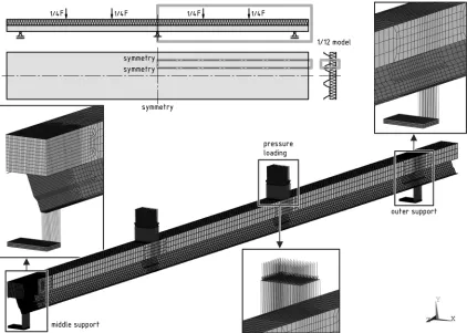
Based on a series of preliminary finite element analyses simulating the experimental setup (see Chapter 2 and Fig. 3), a one-twelfth symmetry finite element model was built, as shown in Fig. 2.
A three-dimensional finite element model of the analysed sandwich panel consists of two different types of finite elements: solid (brick) elements (SOLID185) with large deflection and large strain capabilities were used for the core, and shell elements (SHELL181) that are well suited for large strain nonlinear applications were used to model the outer flat and the inner strongly profiled face. The element formulation is based on logarithmic strain and true stress measures [14]. The combination of brick and shell elements can be used if adequate compatibility conditions are implemented at element interfaces [12] and [15] to [17]. Adhesive layers between the mineral wool core and both steel faces were modelled by using couplings so that the displacement degrees of freedom in all three directions (UX, UY, and UZ) of coincident interface nodes of the elements of the faces and the core were coupled which is common approach in the modelling of bonded layers of different materials (non-metallic or metallic) [18] and [19].
An orthotropic elastic material model was employed to solid elements of the mineral wool core, and a bilinear isotropic hardening material model was applied to steel face shell elements. Mechanical properties and densities of steel faces and mineral wool core based on data provided by the sandwich panel manufacturer are shown in Tables 1 and 2, respectively.
Table 1. Material properties of steel faces
Density [kg/m3]
Elastic modulus [GPa] Yield strength [MPa] Poisson ratio [–] Tangent modulus [MPa] 7850 210 355 0.3 100
Table 2. Material properties of mineral wool core
Density [kg/m3]
Elastic modulus
[MPa] Poisson ratio [–] Shear modulus [MPa]
ρ Ex Ey Ez nxy nyz nxz Gxy Gyz Gxz
Fig. 2. The one-twelfth symmetry finite element model of sandwich panel in double span configuration with applied loads (symmetry and other boundary conditions not shown)
Fig. 3. Experimental setup: sandwich panel in double span configuration with load apparatus
It has to be noted that the coordinate directions used in Table 2 are consistent with the coordinates used in both the finite element and the experimental analyses (see Figs. 2 and 3): the X axis defines a direction parallel to the width of the panel, the Y axis defines a direction parallel to the panel thickness, and
the Z axis defines a direction parallel to the length of the sandwich panel.
panel. 3-D spar elements were also used to apply pressure loading at two loading areas on the flat face, and thus emulate a load apparatus from the experimental setup. A dead load of the load apparatus (a mass of 550 kg) was applied to the model by additional constant pressure load, while a dead load of the sandwich panel was applied by specified gravitational acceleration of 9.81 m/s2 in the Y
direction.
Due to the double symmetry of the tested sandwich panel across two perpendicular planes (parallel to XY and YZ planes) use of one-quarter symmetry model (with width of 412.5 mm, see Fig. 1) would be absolutely correct model. Based on the results from the preliminary analyses that had shown no significant difference in results between “one-quarter” model and the “one-twelfth” model (a sandwich panel model with infinite width i.e. dimension parallel to the X axis, see Fig. 2) the letter model was selected to shorten simulation times. Symmetric boundary conditions were applied at all three vertical “symmetry” planes (marked and labelled “symmetry” on Fig. 2, top left).
The model was solved numerically including large deformation effects.
2 EXPERIMENTAL INVESTIGATIONS
In order to verify the results of numerical analysis, an experimental investigation was conducted at the laboratory of the sandwich panel manufacturer. An experimental setup based on a modified bending
test rig used for a single span panel bending test (A.5 in [5]) with added middle support was used as shown in Fig. 3. An 11-m long single sandwich panel (transverse cross-sectional view is shown in Fig. 1) is placed horizontally on three equally spaced (by a distance of 5 m) simple supports in effectively a two span configuration since the overhangs on both sides were not additionally loaded (dead load only). Transverse loading of the tested panel was accomplished by a hydraulic cylinder. The load from the hydraulic cylinder was applied to the tested panel through a loading apparatus (two equidistant line loads per span).
The total applied transverse load F was measured using a load cell linked between the hydraulic cylinder and the loading apparatus while the midspan deflection u of the inner face was recorded using a linear variable differential transformer (LVDT) (see Fig. 3).
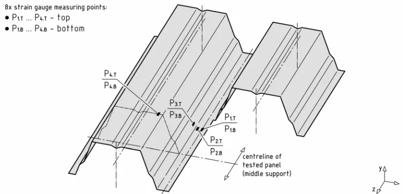
For the measurement of axial bending stresses σz at eight different measuring points (P1.T … P4.T
and P1.B … P4.B, see Fig. 4) strain gauges (in a
quarter Wheatstone bridge configuration) were used. Two strain gauges were attached at each of the four different locations at both the top and the bottom surface of the inner (strongly profiled) steel face in the region above the middle support as shown.
The relevant positions of the stress measuring points on the profiled face of the tested sandwich panel were determined by preliminary finite element analyses. Pairs of measuring points P1.T and P1.B,
and P2.T and P2.B were located on the bottom, flange
while the pair of points P3.T and P3.B was placed on
the web near the bottom flange, and the position of the measuring point pair P4.T and P4.B was selected on the
top flange.
3 RESULTS
The results of both numerical and experimental analysis of the investigated long span length sandwich panel show an expected ultimate failure mode in the form of the wrinkling failure of a profiled face at the middle support due to the interaction between the bending moment and support reaction, as shown in Fig. 5.
a)
b)
Fig. 5. Failure mode of analysed sandwich panel: support reaction capacity of a profiled face at medium support; (view from below) a)
finite element calculation; b) tested specimen
In Fig. 6, calculated results of normal stress distribution σy in a mineral wool core above the middle support are shown. A compressed area of the core extends over 800 mm on each side of a centreline of the support in the longitudinal (Z) direction above the plane part of the top flange of the inner face. In the transverse (X) direction, the stress concentrations in the core above the bend of the top flange can be observed while gradually decreasing in the negative X direction toward a flange stiffener. All shown compressive stress values (up to 0.045 MPa) are
below the adequate proportional stress limit of the mineral wool (which is 0.1 MPa; from data provided by the sandwich panel manufacturer).
Fig. 6. Calculated normal stress σy [MPa] distribution in mineral
wool core above middle support (bottom side, view from below) (F = 30 kN)
Fig. 7. Comparison of experimental and calculated relation load F vs. deflection u of the tested two-span roof sandwich panel
Fig. 8. Calculated axial bending stresses σz [MPa] at top surface
of strongly profiled steel face above the middle support; measuring points P1.T … P4.T are marked and labelled (top side, view from top)
(F = 30 kN)
Fig. 9. Calculated deflections of the tested two-span roof sandwich panel (display created using symmetry expansion) (F = 30 kN)
(because of its high bending stiffness) the support reaction over the large area. Therefore, the checks of compression strength of the core on the support are no longer required [1]. In Fig. 7, a comparison of the applied load F vs. the deflection u obtained from calculated and experimental results (dead load deflections, of both sandwich panel and load apparatus are included and used as zero reference points) is shown. A good agreement is observed between the results in the pre-failure range (the maximum relative difference is 5 %). The value of the ultimate load obtained from experimental results is 28.1 kN and the value of the ultimate load based on calculated results is approximately 30 kN (a relative difference of 7 %).
Fig. 9 shows the calculated total deflection distribution (deflections due to the dead load of sandwich panel and load apparatus included) along the investigated sandwich panel in a double span configuration at calculated ultimate load (F = 30 kN).
Fig. 8 shows the calculated distribution of axial bending stresses σz [MPa] on the top surface (view from the top) of the inner steel face above the middle support (at a calculated ultimate load F = 30 kN). Wrinkles in the bottom flange and in the web (near bottom flange) of the profiled face due to the compression stresses can be noticed. The measuring points (P1.T … P4.T) where the axial bending stresses σz at the top surface were measured in the experiment
are also marked and labelled.
In Fig. 10, the calculated and experimental axial bending stresses σz on the top surface (at measuring
points P1.T … P4.T) and the bottom surface (at
measuring points P1.B … P4.B) of the inner steel face
above the middle support compared to applied load F are presented. The compressive axial stress values can be observed in points below the neutral axis of the face, i.e. points P1.T … P3.T and P1.B … P3.B;
and tensile stress values in points P4.T and P4.B that
are above the neutral axis of the face as expected. A reasonably good agreement between the results can
be noticed in the pre-buckling load range. The relative differences at a load value of 20 kN (at ⅔ value of ultimate load F = 30 kN) are between 28 % (at points P2.B and P3.T) and 33 % (at point P4.T). However, it
has to be noted that a bad quality bonding of the strain gauge at the measuring point P4.T was observed in the
post-test inspection. But, what is more important is the thorough agreement in a size relation between the stresses on the top and bottom surfaces of the steel face at each of the four measuring locations, i.e. a positive difference between the stresses at measuring points P1.T and P1.B, and P2.T and P2.B, respectively, and a
negative difference between the stresses at measuring points P3.T and P3.B, and P4.T and P4.B, respectively.
The established differences in the axial bending stresses are consistent with the deformed shape of the profiled steel face at corresponding points, as shown in Fig. 8 (and consequently also in Fig. 5).
5 CONCLUSIONS
6 REFERENCES
[1] Davies, J.M. (2001). Lightweight Sandwich Construction. Blackwell Science, Oxford, DOI:10.1002/9780470690253.
[2] Zenkert, D. (1997). The Handbook of Sandwich Construction.
Chameleon Press, London.
[3] Hassinen, P., Martikainen, L. (1994). Analysis and Design of
Continuous Sandwich Beams. 12th International Specialty Conference on Cold-Formed Steel Structures, p. 523-538.
[4] Hassinen, P., Martikainen, L. (1996). Design Models of
Continuous Sandwich Panels. 13th International Specialty Conference on Cold-Formed Steel Structures, p. 293-307.
Fig. 10. Comparison of experimental and calculated axial bending stresses σz [MPa] in relation to applied load F [kN]
at the top and the bottom surface of inner strongly profiled steel face at measurement points (P1.T … P4.T and P1.B … P4.B)
[5] EN 14509:2013. Self-Supporting Double Skin Metal Faced Insulating Panels - Factory Made Products - Specifications.
European Committee for Standardization, Brussels.
[6] Misiek, T., Hassinen, P. (2010). Unified Approach for the Local Buckling Of Sandwich Panels and Trapezoidal Sheeting. Proceedings: W056 – Special Track 18th CIB World Building Congress, Salford, p. 14-26.
[7] Hassinen, P. (1997). Evaluation of the compression strength
of profiled metal sheet faces of sandwich panels. Thin-Walled Structures, vol. 27, no. 1, p. 31-41, DOI:10.1016/0263-8231(96)00022-5.
[8] EN 1993-1-3:2006. Eurocode 3: Design of Steel Structures – Part 1-3: General Rules – Supplementary Rules for Cold Formed Members and Sheeting. European Committee for Standardization, Brussels.
[9] EN 1993-1-5:2006. Eurocode 3: Design of Steel Structures – Part 1-5: Plated Structural Elements. European Committee for Standardization, Brussels.
[10] Pokharel, N., Mahendran M. (2004). Finite element analysis
and design of sandwich panels subject to local buckling effects. Thin-Walled Structures, vol. 42, no. 4., p. 589-611,
DOI:10.1016/j.tws.2003.08.002.
[11] Pokharel, N., Mahendran M. (2005). An investigation of lightly profiled sandwich panels subject to local buckling and flexural
wrinkling effects. Journal of Constructional Steel Research, vol. 61, no. 7, p. 984-1006, DOI:10.1016/j.jcsr.2004.12.008.
[12] Rädel, F., Lange, J. (2011). Tragfähigkeit von
Sandwichelementen mit profilierten Deckschichten und
Öffnungen. Stahlbau, vol. 80, no. 9, p. 656-661, DOI:10.1002/ stab.201101469.
[13] Ilić, I., Petrovic, Z., Maksimović, M., Stupar, S., Stamenković, D. (2012). Computation method in failure analysis of
mechanically fastened joints at layered composites. Strojniški vestnik – Journal of Mechanical Engineering, vol. 58, no. 9, p. 553-559, DOI:10.5545/sv-jme.2011.157.
[14] N/A (2012). Elements Reference. Release 14.5
Documentation for ANSYS. Ansys Inc., Canonsburg.
[15] Kovačević, D., Budak, I., Antić, A., Kosec, B. (2011). Special finite elements: Theoretical background and application. Tehnički vjesnik - Technical Gazette, vol. 18, no. 4, p. 649-655.
[16] Croccolo, D., De Agostinis, M., Vincenzi, N. (2011). structural
analysis of an articulated urban bus chassis via FEM: a methodology applied to a case study. Strojniški Vestnik – Journal of Mechanical Engineering, vol. 57, no. 11, p. 799-809, DOI:10.5545/sv-jme.2011.077.
[17] Čuk, M., Štih, S., Jerman, B. (2013). Finite element analysis of
sandwich panels with longitudinal joints and large openings.
Tehnički vjesnik - Technical Gazette, vol. 20, no. 2, p. 275-284.
[18] Djemana M., Hrairi M. (2016). Modelling and simulation
of impedance-based damage monitoring of structures.
International Journal of Simulation Modelling, vol. 15, no. 3, p. 295-408, DOI:10.2507/IJSIMM15(3)1.338.
[19] Wang Y., Lu Y. J., Si C. D., Sung P. (2016). Tire-pavement

![Fig. 5.Fig. 6. Calculated normal stress σy [MPa] distribution in mineral wool core above middle support (bottom side, view from below)](https://thumb-us.123doks.com/thumbv2/123dok_us/8948769.1858137/5.598.69.276.253.537/fig-calculated-normal-stress-distribution-mineral-middle-support.webp)

![Fig. 10. Comparison of experimental and calculated axial bending stresses at the top and the bottom surface of inner strongly profiled steel face at measurement points (σz [MPa] in relation to applied load F [kN] P1.T … P4.T and P1.B … P4.B) of the tested two-span roof sandwich panel](https://thumb-us.123doks.com/thumbv2/123dok_us/8948769.1858137/7.598.75.521.91.595/comparison-experimental-calculated-stresses-strongly-measurement-relation-sandwich.webp)
