Clay Minerals (1972) 9, 407.
A
S I M P L E D I F F R A C T O M E T E R
H E A T I N G
G. B R O W N , B. E D W A R D S , E. C. O R M E R O D AND A. H. W E I R
Rothamsted Experimental Station, Harpenden, Hertfordshire
S T A G E
(Received 16 March 1972)
A B S T R A C T : The construction is described of a heating stage for examining oriented clay specimens in a Philips' diffractometer. The stage, which is simple and cheap to make, is interchangeable with standard specimen holders, operates over the range 20- 265~ and does not require the diffractometer to be specially modified. The maximum temperature attained at the surface of the specimen collapses freely-expanding Mg- saturated vermiculite and prevents re-expansion of layer silicate minerals once they have been collapsed.
I N T R O D U C T I O N
Changes in X-ray diffraction patterns produced by chemical and thermal treatments are often used as diagnostic tests for identification of clay minerals. Rehydration after heating, which can occur rapidly, m a y Iead to errors. Milne & Warshaw (1956) recommended the use of dry air in the specimen chamber of a diffractometer to prevent rehydration. We have used a heated specimen stage for the same purpose.
4 . 0 x 3 - 2 x o - 6 cm. It uses a small electrical heater set in a duralumin block, which is in contact with the glass slip, but otherwise supported by asbestolite. Thus, for a given temperature at the clay specimen surface, heat reaching the stage and transferred to the goniometer is minimized and special modifications for cooling are unnecessary.
Although the heating stage described is specifically made for clay mineral studies using a Philips' PW 1050/25 dittractometer, little modification in design would be needed to make a stage for use with other diffractometers or with other kinds of specimens.
D E S C R I P T I O N Figure 1 shows the components of the heating stage*.
The insulating block, (1) is formed from Asbestolitet. Its reference face (S), which is held against the reference surface of the goniometer shaft, is ribbed to minimize heat transfer to the shaft.
The metal block, (2) is made of duralumin. When components 1 and 2 have been permanently fixed together, surface (S) is machined parallel to, and 0-050 in. (1-27 mm) above, surface (P). The specimen slips are prevented from sliding on surface (P) by the small phosphor bronze bracket (9).
The heating coil, (14) is positioned in the cylindrical hole in block 2 inside a double insulating sleeve of woven glass fibre (12) and protected by a steel outer cover (11). This cover is held in position by two screws that also attach the mica-filled P.T.F.E. insulating block (4) to block (2).
The heating coil is formed from a soldering iron element, 15 W, 240 V, Type CN manufactured by A.N.T.E.X. L t d , .
As supplied, the ceramic tube former of the heater is too long to fit the sample holder. It is therefore removed from its stainless steel sheathing tube and woven glass fibre cover and shortened to give a total length of 4.3 cm. The leads connecting the heating coil to the supply have to be re-attached following this operation. The ends of the wire of the heating coil are twisted on to 0"25 ram-diameter nichrome wires and then welded using an electric arc from a pointed carbon electrode and a 40-50 V battery. The modified heating coil is then resleeved in its glass fibre and steel covers, secured in block (2), and the leads, cut to about 3 cm and insulated with silicone rubber sleeving, are soldered Io the terminal pins (6), in block (4). A control unit conveniently supplies power from the 240 V mains supply through a small auto-transformer to give 0-270 V to the heating coil. Figure 2 shows a suitab!e circuit. Thin insulated flexible leads from XY (Fig. 1) connect the healing stage to the transformer unit. The heating stage leads are brought into the specimen chamber of the diffractometer through the removable cover. We have modified a replacement
* Working drawings for construction may be obtaincd from the authors. t Asbestolite is a composite of asbestos and cement.
Diffractometer heating stage
C~
2 v
:
P
d
409
Fie. 1. Diagram showing components of the heating stage. 1. Insulating and support unit; 2. Heating unit; 3. Brass screws 10 B.A.C.S.H.; 4. Insulating block; 5. Brass screws 8 B . A . R . H . ; 6. Terminal pins; 7. Pick-up tags; 8. Soldered connections from heater; 9. Slide retaining bracket; 10. Brass screw 10 B . A . R . H . ; 11. Steel outer cover; 12. Woven glass-fibre insulation (2 layers); 13. Ceramic tubular heater support; 14. Heater winding (0"003 mm diam.); 15. Ceramic cement; 16. Nichrome connecting
2
2
3(
)
5
4
f
.
6
5 O x O
7
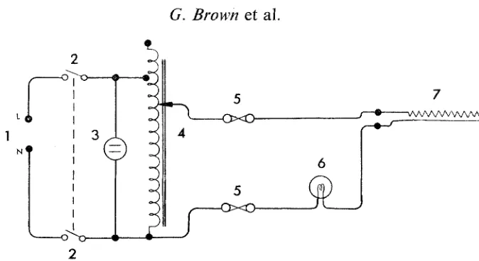
FIG. 2. Circuit diagram for the control unit of the heating stage. 1. Mains, 240 V; 2. ON/OFF switch; 3. Mains ON, neon; 4. Autotransformer, 2 A rating, input 240 V, output 0-270 V; 5. Fuse, 200 mA; 6. Heater ON, filament lamp, 6 V, 0"1 A; 7, Stage
heating element.
2
Flo. 3. Diagram showing components of the modified specimen chamber cover, 1. Modified cover plate; 2. Movable sector; 3. Lead lining; 4. Knurled securing knob;
5, Brass washer 6 B.A.; 6, Brass screw 6 B.A, C . H
Diffractometer heating stage
411
and the 3 mm gap between the perimeter of the cover and the flange of the sector. With the sector in position scattered radiation could not be detected outside the radiation shielding.
T E M P E R A T U R E C A L I B R A T I O N
The temperature of the specimen is controlled by varying the voltage applied to the heating coil. Equilibrium at each temperature is attained in about 10 rain and a calibration curve of temperature versus applied voltage is given in Fig. 4. The temperature of the clay specimens was determined by observing the melting of powdered crystals of pure substances of known melting points in contact with the clay surface. The temperature range over the surface of the specimen does not exceed the error in measurement, estimated to be about + 2~
D ~
"O
2 2 7 0
2 5 0
2 3 0
210
190
[70 i
150 :
130 II0
o/
9
/
/
/
e,~ e J./
7 0 :
5 0 l I I t I I I l r I I f [ I I I I I 1 8 0 1(30 120 140 160 1,90 2 0 0 2 2 0 2 4 0 2 6 0 2 8 0
Volts a c r o s s heating coil
F[o. 4. Calibration curve of specimen; surface temperature against applied voltage.
M.P.~ M.P.~
p-dichlorobenzene 53 citric acid (anhyd.) 153 stearic acid 6 8 - 5 salophene 190 citric acid 100 dicyandiamide 210 phenacetin 135 silver nitrate 212
cholesterol 149 tin 232
M E A S U R E M E N T O F 20
Because the heated stage is a composite of different materials, tests were made to discover whether heating caused the position of the specimen surface to change. Measurements of 20 from a specimen of diamond powder, which has a very small coefficient of thermal expansion (Skinner, 1957), showed that over the temperature range 20-250~ changes in 20 caused by thermal expansion of the instrument do not exceed 0.01 o 20.
The only aberration introduced by replacing conventional specimens with those we use for examination of clay films occurs because the glass slips, which are cut from 7.62 )< 3.81 cm microscope slides, may range in thickness between 1.17 m m and 1-35 ram. The surface of the clay film is therefore usually displaced from the reference plane of the goniometer causing shifts in the position of reflections, to larger angles if the specimen surface is inside the focussing circle and to smaller angles if the surface is outside, by
~x20 = 2S cos
O/R
radians,where S is the distance between the specimen surface plane and the reference plane, and R is the radius of the goniometer (Wilson, 1950). For unheated speci- mens an internal standard can be used for correction, but because of changes in spacings caused by thermal expansion, it is difficult to use internal standards to correct the observed 20 values of heated specimens. For both unheated and heated specimens of the kind described here, a correction can be made conveniently for routine work by measuring the thickness of the slip + clay film with a micrometer and reading the corresponding a20 from a graph or table.
U S E F O R C L A Y S T U D I E S
Plate 1 gives examples of diffractometer patterns made using the heating stage. The sample was a Mg-vermiculite, AP3, c.e.c. = 190 m e q / 1 0 0 g, prepared by Newman (1967) by removing potassium from phlogopite. The sample was heated to various temperatures on the heating stage and chart recordings made of the first order basal reflection at each temperature. At room temperature (Plate la), the reflection has 20 = 6.17% d = 14.3 A corresponding to the two-layer water 14.36 A phase of Walker (1961). Heating at 100~ for 20 rain produces the one-layer water phase d = 11.59 A (Plate lb) and heating to 265~ the maximum attainable tem- perature, for 30 min gives a spacing of 10.1 A (Plate lc). Further heating at 265~ for 2.5 hr causes little change in the position of the reflection (Plate ld). Heating the same sample at 700~ for 4 hr in an electric furnace followed by cooling to almost 2 5 0 c c and transfer to the heating stage at 265~ produced a further small collapse giving a spacing of 9"9 A.
PLATE 1
Diffractometer traces of basal reflections of Mg-saturated vermiculite AP3 held at various temperatures on the heated stage. (a) specimen at 20~ (b) specimen at 100~ for 20 min;
(c) specimen at 265~ for 30 rain; (d) specimen at 265~ for 2"5 hr.
General conditions. Specimen: a slurry of vermiculite in water was dried to give a very thin oriented film, which with the glass slip measured 49 x 10 x 1.27 mm. Tube: CuK radiation, 40 kV, 20 mA. Goniometer: scan speed l~ divergence slit 1/4 ~ receiving slit 0-1 ram, anti- scatter slit 1 ~ 0.178 m m Ni filter. Proportional counter: full scale deflection (a) 1 x 10⁴ c.p.s.,
(b), (c), (d) 4 x 10³ c.p.s. Chart speed: 1200 ram/hr.
A C K N O W L E D G M E N T S
We t h a n k E. M. Thomson and M. J. Williamson, Soil Survey of England and Wales, for preparing
the diagrams.
R E F E R E N C E S
GOI.DSC~aDT H.J. (1964) High Temperature X-ray Diffraction Techniques, Bibliography 1. Inter- national U n i o n of Crystallography Commission on Crystallographic Apparatus.
MILNE I.H. & WARS~AW C.M. (1956) Clays and Clay Minerals (A. Swineford, editor), p. 22. Publica- tion 456. Nat. Acad. Sci. - - Nat. Res. Counc., Washington.
NEWMAN A.C.D. (1967) Clay Minerals, 7, 215. SKINNER B.J. (1957) Am. Miner. 42, 39.
WALKER G.W. (1961) X-ray Identification and Crystal Structures o f Clay Minerals (G. Brown, editor), Chap. VII, pp. 305-306. The Mineralogical Society, London.
WILSON A.J.C. (1950) Y. scient, lnstrum. 27, 321.
A P P E N D I X
A J I G F O R C U T T I N G G L A S S S L I P S U S E D I N X - R A Y D I F F R A C T O M E T R Y O F C L A Y S
P. A. M A D G E T T AND B. S. E D W A R D S
Rothamsted Experimental Station, Harpenden, Hefts.
As noted above, the specimens f o r X-ray diffractometry were formed by drying a slurry on 3"81 X 1.27 )< 0.12 cm (1-5)< 0.5 ;< 0.5 in.) glass slips. These slips are conveniently made by cutting standard 7"62 )< 3"81 cm (3 X 1.5 in.) microscope slides in the jig in Fig. A5. Slides 0-127 cm (0.05 in.) thick are selected, placed in the jig, and scored with a standard laboratory tungsten carbide glass knife which has had its point sharpened to subtend an angle of not more than 30 ~ A laboratory diamond glass knife is unsatisfactory for this purpose as slivers of glass catch under the diamond mount and give a jagged cut that breaks unevenly.
4 1 4
G. Brown
et al.
|
... ... ... _ ...
;I
il
!l
!1
il
~..~.
9_
Front view Side view Back view
-@
--@
7/~/, 0
o Section ,~,A
I 2 3 4 in.
[ I I t il
I I ] I I I I I
2 3 4 5 6 7 B 9 10 cm
Fro. A5. Details of construction. A. Body, aluminium; B. Bridge, mild steel, cad- mium plated; C. Head, aluminium; D. Pad, rubber; E. Springs, 0'290" x 0"012" tempered spring steel; F. Clamp, 88 x ~" mild steel, cadmium plated; G. Screws,
3 t ,