Inertial force balance and ADAMS simulation of the oscillating sieve and
return pan of a rice combine harvester
Chuncai Wei
,
Lizhang Xu
*,
Jianting Wang
,
Yaoming Li
(Key Laboratory of Modern Agricultural Equipment and Technology, Ministry of Education; School of Agricultural Equipment and Engineering, Jiangsu University, Zhenjiang 212013, China)
Abstract: To reduce the inertial force of the oscillating sieve and return pan of a rice combine harvester, partial equilibrium was adopted. Firstly, based on the kinematic analysis of a slider-crank mechanism, the appropriate mass of counterweight intervals was achieved. Then, an ADAMS dynamic simulation was used to determine the optimum balance mass of the oscillating sieve and return pan individually. Considering the relative motion between the return pan and the oscillating sieve, the overall inertial force of the two parts would be reduced. The simulation results indicated that the optimum counterweight of the oscillating sieve was 15.5 kg based on an analysis of the movement tracks of the mass center and overall inertial force. The results also showed that the overall balance of inertial force not only reduced the counterweight but also decreased the overall inertial force of the oscillating sieve and return pan. Finally, a search for the most suitable crank initial angle of the return pan to reduce the overall inertial force and optimize the overall balance revealed three groups of initial angles: φ=0°, φ=45°, and φ=90°. The results indicated that arranging the initial angle of the crank of the oscillating sieve and return pan in the same position (φ=90°) was the most favorable for reducing the overall inertial force. In this situation, the optimum counterweight of the oscillating sieve was only 14.0 kg. The results can provide references for the design of the overall balance of the inertial force in the cleaning components of a combine harvester.
Keywords: rice combine harvester, oscillating sieve, return pan, inertial force balance, ADAMS DOI: 10.25165/j.ijabe.20181101.2978
Citation: Wei C C, Xu L Z, Wang J T, Li Y M. Inertial force balance and ADAMS simulation of the oscillating sieve and return pan of a rice combine harvester. Int J Agric & Biol Eng, 2018; 11(1): 129–137.
1 Introduction
During the cleaning process of a rice combine harvester, the oscillating sieve and return pan are influenced by the inertial force of rotary motion in addition to external loads. The inertial force affects the frame and other parts of the combine harvester, which can lead to strong vibration and noise directly influencing the reliability and service life of a combine harvester[1-3]. It is necessary to reduce the impact of the inertial force of the oscillating sieve and return pan as much as possible. Complete balance and partial equilibrium are the main two methods used to balance the inertial force[4]; however, complete balance is not a
suitable method for the oscillating sieve or return panbecause the counterweight may outweigh the mechanism itself and the interference caused by the counterweight can thus directly or indirectly affect the normal functioning of other parts[5]. Even if the oscillating sieve could achieve complete balance, this complete balance would lead to input torque, causing the counter-force of the connecting frame pair to increase considerably[6]. Therefore,
considering the actual structure of the oscillating sieve and the
Received date: 2016-11-08 Accepted date: 2017-07-06
Biographies: Chuncai Wei, Master candidate, research interests: crop cleaning loss monitoring, Email: [email protected]; Jianting Wang, Master candidate, research interests: corn threshing device design, Email: [email protected]; Yaoming Li, PhD, Professor, research interests: design and theory of modern agricultural equipment, Email: [email protected].
*Corresponding author: Lizhang Xu, PhD, Professor, research interests: intelligent harvesting machinery and precision agriculture. School of Agricultural Equipment Engineering, Jiangsu University, Zhenjiang 212013, Jiangsu, China. Tel: +86-13815171180, Email: [email protected].
technology. Based on the kinematic and dynamic modes of a crank slide-type oscillating sieve, the inertial force of the oscillating sieve was obtained and optimized using Matlab[13].
The above related research obtained specific results on reducing the inertial force of a slider-crank mechanism and other parts of a combine harvester. However, with respect to balancing an oscillating sieve, the research only optimized the inertial force equation or only adopted a simplified model of the slider-crank mechanism to simulate the oscillating sieve, resulting in a large error between the theoretical counterweight and practical counterweight. In addition, no relevant papers on the inertial force offset and simulation of the oscillating sieve and return pan as a whole have been published to date. The above studies ignored the inertial force offset of the two parts in the process of mutual movement; as a result, the counterweight was not the actual optimal balance weight.
In this study, partial equilibrium of the inertial force balance was used to calculate the counterweight intervals of the slider-crank mechanism and the optimum mass in the counterweight interval obtained with ADAMS software. Based on a comprehensive consideration of the relative motion of the oscillating sieve and the return pan, the optimum mass for the overall balance of two devices was obtained, providing a design method for the counterweight that addresses the inertial force reduction of the oscillating sieve and return pan.
2 Materials and methods
2.1 Working principle of the oscillating sieve and return pan To address the harvesting requirements for high-yield rice, a new type of threshing and cleaning system was developed, composed of a transverse tangential thresher, a longitudinal rotor, a multi-duct fan and a double-layer oscillating sieve[14], as shown in
Figure 1. The tangential thresher is used to thresh mature and easily threshed rice kernels, and the remaining kernels in the panicles are threshed by the longitudinal rotor. The mixture from the tangential and longitudinal concaves includes kernels, short straw, and light materials. The fan has to generate an even airflow with proper air speed over the sieves to separate grain kernels from straw and chaff, collectively known as material other than grain (MOG)[15].
1. Tangential thresher 2. Longitudinal threshing cylinder 3. Tailings window 4. Return pan 5. Tailings auger 6. Lower sieve 7. Upper sieve 8. Clean grain auger 9. Oscillating pan 10. Multi-duct centrifugal fan
Figure 1 Schematic showing new type of rice threshing and cleaning system
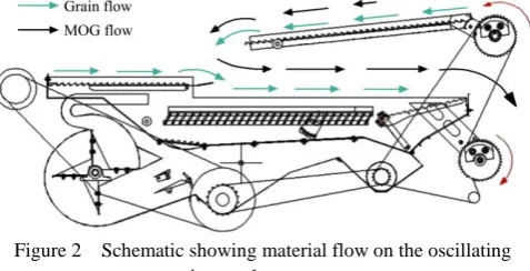
The mechanical process of the new threshing and cleaning device can be summarized as follows. The mass of composite materials from the tangential threshing cylinder drops into the oscillating pan located in front of the sieve, on which they are progressively deflected toward the front of the upper sieve. Subsequently, the mass of composite materials from the longitudinal axial-flow threshing cylinder drop directly onto the return pan. The combined effects of fan airflow and the oscillating shaker remove light materials from the composite materials from two cylinders to assist in positioning kernels over the sieve openings and moving particles along the sieve surface if they did not pass through the sieve openings. Finally, the clean kennels passing through sieve openings are gathered and conveyed to the tank by the clean grain auger. Some composite materials that do not pass through the sieve openings fall into the tailings auger; they are conveyed to the return pan from the tailing window, while the long straw is conveyed by the oscillating chaffer toward the rear of the combine[16], as shown in Figure 2.
Figure 2 Schematic showing material flow on the oscillating sieve and return pan
2.2 Dynamic analysis of the oscillating sieve and return pan Both the oscillating sieve and return pan can be simplified as a slider-crank mechanism[17] . Because the crank length is much shorter than the connecting rod length (approximately 1:100), it can be considered that the moving direction of the slider and the rotation center of the crank are in the same straight line. Therefore, the in-line slider-crank mechanism was regarded as the analysis model of the oscillating sieve and the return pan, as shown in Figure 3.
Figure 3 Schematic showing the counterweight of an in-line slider-crank mechanism
2.2.1 Inertial force and counterweight of the slider-crank mechanism
Assuming the masses of the crank and connecting rod are m1
and m2, respectively, that the mass centers are S1 and S2,
respectively, and that the slider mass is m3, according to the static
mass substitution method, m1 is replaced with mA1 and mB1, and m2
are replaced with mB2 and mC2, respectively. Thus, the inertia of
1 2
2 3
B B B
C C
m m m
m m m
(1)
where, B1 1
c
m m
l
, B2 2
b
m m
l
, C2 2
a
m m
l
, and m3 is the mass
of the slider.
In this mechanism, the displacement of the slider is as follows:
cos cos
Sr θ l φ (2)
where, r is the length of the crank; θ is the rotation angle of the crank, and φ can be obtained from the trigonometric function
relation: sinφ lsinθ λsinθ r
and
1
2 2 2
cosφ (1 λ sin θ) , where
λ is the ratio of the crank length and the connecting rod length. cosφ can expand into the angle θ progression; for this mechanism, λ=0.01 and the high-order terms containing λ can be omitted. To solve the displacement S, the second derivative can be omitted, providing the acceleration of C:
2
(cos cos 2 )
c
a r θ θ λ θ
(3) From the above analysis, the rotating inertial force of B and moving inertial force of C can be obtained:
2
B B
F m r θ
(4)
2
(cos cos 2 )
C c c c
F m a m r θ θ λ θ
(5) The term FC containing cosθ is called the first-order inertial
force; the term FC containing cos2θ is called the second-order
inertial force. According to the partial equilibrium method, a counterweight (Figure 3) is set at the appropriate reverse distance of the crank and the rotation inertial force FB can be balanced by
the mass of D:
2 2
1
D B
m r θ m r θ
; thus,mD1rrmB
(6)
Similarly, to balance the moving inertial force generated in the horizontal direction, a counterweight mD2 should also be set;
however, that counterweight would exert an unnecessary vertical inertial force, and the second-order inertial force cannot be balanced. In this mechanism, the second-order inertial force is quite small and can thus be ignored. The horizontal inertia and vertical inertial forces caused by mD2 are as follows:
2 2 2 2 cos sin x D y D
F m r θ θ
F m r θ θ
(7)
In the present comprehensive analysis, a coefficientkwas used to multiply mD2 to balance the horizontal inertial force while the
vertical inertial force was not too large. In general, k is 1/3-1/2. Based on the above analysis, the counterweight is composed of two parts, mD1 and kmD2:
1 2 ( )
D D D r B C
m m km m km
r
(8)
2.2.2 Inertial force and counterweight of the oscillating sieve and the return pan
The return pan comprises a roller, vibrating board and eccentric shaking shaft (Figure 4); the eccentric shaking shaft is simplified into a crank, the vibrating board is simplified into a connecting rod, and the roller is simplified into a slider as well. Based on the above calculation of the slider-crank mechanism inertial force and counterweight analysis, the proper counterweight intervals could be combined with the actual data of the oscillating sieve and return pan. The eccentricity of the eccentric shaking
shaft was 15 mm, and the mass was 1.0 kg, and the mass center was located at a distance of 12.3 mm from point A; the rotational speed was 350 r/min. The length of the vibrating board was 1045 mm, the mass center was located at a distance of 12.3 mm from point B; the mass of the vibrating board was 23.7 kg, and the mass of the roller was 0.26 kg.
1. Roller 2. Vibrating board 3. Eccentric shaking shaft Figure 4 Return pan structure diagram
From the above formulas, the following can be calculated: mB2=11.1 kg, mB1=0.8 kg, mC2=12.6 kg. Thus, mB=11.9 kg and
mC=12.86 kg. The counterweight was installed at the reverse of
the crank: r′=45 mm, when, k=1/3; when mD=6.1 kg, k=1/2. Thus,
the counterweight intervals of the return pan are 5.4-6.1 kg. The oscillating sieve comprises an eccentric shaking shaft, a screen board and a roller, as shown in Figure 5.
1. Roller 2. Vibrating board 3. Eccentric shaking shaft Figure 5 Oscillating sieve structure diagram
In the slider-crank mechanism model of the oscillating sieve, the crank length is 15 mm, the mass is 1.0 kg, and the mass center is located at a distance of 12.3 mm from point A; the rotational speed is 350 r/min. The length of the connecting rod is 1378 mm, the mass center is located at a distance of 448 mm from point C, and the mass is 90.4 kg. The rolling wheel mass is 0.26 kg. Thus, m'B=29.5 kg and m'C=61.26 kg. The counterweight of the
oscillating sieve was also installed in the reverse of the crank: r'= 45 mm. Finally, the counterweight intervals of the oscillating sieve are 16.7-20.1 kg.
2.2.3 Overall inertial force balance of the oscillating sieve and the return pan
During the working process of the oscillating sieve and the return pan, the crank shaft is driven to rotate by a chain reverse wrapped around a chain wheel, with the cranks of the oscillating sieve and the return pan rotating in opposite directions. Therefore, in the balance of the inertial force of the oscillating sieve and the return pan, the mutual movement relationship between the two mechanisms should be considered, and for the whole mechanism, the rotation directions of the two cranks are opposite and thus the overall inertial force of the two parts can be reduced. This feature can be utilized to reduce the counterweight mass of the oscillating sieve, steady the operation of the mechanism and reduce the input torque and energy consumption.
setting the counterbalance. According to the same principle, when the overall balance was taken into account, the mass of the return pan was replaced with the combined masses B and C, and the mass of the oscillating sieve was replaced with the combined masses of B' and C', as shown in Figure 6.
Figure 6 Schematic showing the oscillating sieve and return pan mechanism
The moving inertial force generated by mass C and C' is as follows: 2 1 2 2 cos cos
C C C C
C C C C
F m a m r θ θ
F m a m r θ θ
(9)
where, cosθ1cos( ωt φ), cosθ2cos(ωt 90 ), and φ is an
arbitrary initial angle.
According to Equation (9), the moving inertial force generated by mass C and C' could be reduced in the movement. The following discussion is about how to obtain the most suitable initial angle of the return pan’s crank to minimize the overall inertial force of the oscillating sieve and return pan when the initial phase of the oscillating sieve is 90° because of structural design requirements.
The resultant force from the inertial force in the horizontal direction (X direction) of the oscillating sieve and return pan system is as follows:
2
1 2
( cos cos )
CC C C
F r θ m θ m θ
(10)
In one cycle, the average moving inertial force was compared with the average moving inertial force without considering the inertial force offset:
2
1 2 2
1 1 ( ) T CC T T T C C T T F dt T η
F dt F dt
T
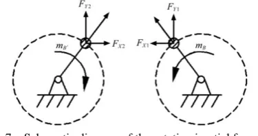
(11)In similar ways, the rotating inertial force can also be offset (Figure 7).
Figure 7 Schematic diagram of the rotating inertial force of the oscillating sieve and return pan
The rotating inertial force caused by mB and m'B can be
decomposed into the X and Y directions: X direction:
2 1 1 2 2 2 cos cos X B X B
F m r θ θ
F m r θ θ
(12)
Y direction:
2 1 1 2 2 2 sin sin Y B Y B
F m r θ θ
F m r θ θ
(13)
The resultant forces in the X and Y directions are as follows:
1 2
1 2
X X X
Y Y Y
F F F
F F F
(14)
The resultant inertial force of the oscillating sieve and return pan is as follows:
2 2
X Y
F F F
(15)
In one cycle, the average resultant rotating inertial force was compared with the average inertial force without considering the inertial force offset:
2
2 2 2 2 2
1 1 ( ) T T T T B B T T Fdt T η
m r θ dt m r θ dt
T
(16)Inserting the data into the formulas provides the following conclusions:
1)when φ=45°, η1=0.72, and η2=0.86, both moving inertial
force and rotating inertial force were reduced to some degree based on the balance of the inertia and according to the above formulas. The counterweight mass of the oscillating sieve was m'D2=13.9-16.5 kg.
2)when φ=90°, η1=0.65, and η2=0.71, the maximum offset of
the inertial force and the overall inertial force was minimal. Thus, φ=90° was the most suitable initial angle of the return pan’s crank. According to the above formulas, the counterweight mass of the oscillating sieve was m'D2=11.4-13.7 kg.
3)when φ=0°, η1=0.74, and η2=0.77, both the moving inertial
force and rotating inertial force were reduced to some degree, but the decreased degree of the overall inertial force was less. The counterweight mass of the oscillating sieve was m'D2=13.2-15.8 kg.
3 Simulation analysis of the oscillating sieve and
return pan
3.1 Movement tracks of the mass center and inertial force analysis of the return pan
Based on the definition of the inertial force balance, when the total mass of the mechanism is constant, the greater the acceleration of the mass center, the greater the inertial force. Therefore, in the fixed cycle, the greater the range of motion of the mass center, the greater the acceleration and inertial force. Hence, the target of the inertial force balance is to make the movement range of the mass center as small as possible in one cycle.
fixed on the ground, and the motion pair between the side board and the eccentric shaking shaft was a rotating pair. During the simulation process, the eccentric shaking shaft speed was 2100 (°)/s (350 r/min).
Figure 8 Simulation model of the return pan in ADAMS
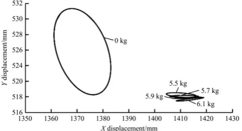
In the counterweight interval (5.4-6.1 kg), four sets of data were selected as the variable: 5.5 kg, 5.7 kg, 5.9 kg and 6.1 kg. The simulation time was 0.5 s, and the step size was 0.01 s. The relationship between the position coordinates of the mass center of the return pan and time was obtained and processed in EXCEL (Figures 9 and 10). The return pan in the Z direction did not have movement displacement; therefore, in the X and Y dimensions, the movement tracks of the mass center were determined, as shown in Figures 11 and 12.
Figure 9 Displacement of the mass center in the X direction
Figure 10 Displacement of the mass center in the Y direction
Figure 11 Movement tracks of the mass center under different counterweights
Figure 12 Movement tracks of the mass center under different counterweights compared with no counterweight
In the simulation process, different counterweight settings would change the mass center stability and balance. The following conclusions can be drawn from Figures 9-12:
(1) The mass center moved in the X and Y directions with 0.17 s of one cycle, the fluctuation in the X direction was larger (14 mm), and that of the Y direction was relatively small (1.1 mm).
(2) Compared with no counterweight, the X displacement decreased from 21.9 mm to 9-11 mm and the Y displacement decreased from 11.1 mm to 0.2-0.6 mm after adding the counterweight.
(3) Different counterweights resulted in different movement tracks of the mass center. When the counterweight was 5.9 kg, the movement tracks range of the mass center reached its minimum of 1.7 mm2. The corresponding balance effect was also optimal. Thus, it can be concluded that the optimum counterweight was 5.9 kg.
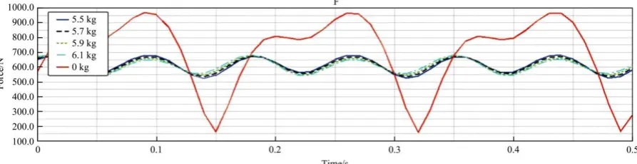
In the above images, a reflection of the inertial force changes through the movement tracks of the mass center was intuitive but cannot accurately show the specific numerical value of the inertial force. If the counterweight is in inappropriate position, it may cause excessive force on the motion pair. Specifically, at the bearing connecting the crank and frame, the bearing may be damaged because of the impact and is thus not conducive to balancing the return pan. Thus, it was necessary to calculate the inertial force of the return pan. Through the ADAMS/Postprocessor, the counter-force in the X and Y directions at joints (Figures 13 and 14, respectively) is shown and the inertial force is obtained under different counterweights, as shown in Figure 15.
From Figures 13-15 and Table 1, the following can be concluded:
(1)Compared with no counterweight (red curve in figures), the peak-to-peak value of the counter-force in the X direction decreased from 850 N to 1408 N after the addition of counterweights and the peak-to-peak value of the counter-force in the Y direction decreased from 586 N to 275 N. The degree of reduction was substantial, showing that the counterweight achieved the balance of the inertial force.
(2)Compared with no counterweight, after the addition of counterweights, the mean value, RMS, and peak-to-peak values all decreased greatly, proving the effectiveness of achieving partial equilibrium by setting the counterweight.
Figure 13 Counter-force in the X direction under no counterweight and different counterweight qualities
Figure 14 Counter-force in the Y direction under no counterweight and different counterweight qualities
Figure 15 Inertial force of return pan under no counterweight and different counterweight qualities
Table 1 Inertial force under different counterweight qualities
Mass/kg Min/N Max/N Mean value/N RMS Peak-to-peak value/N
0 159 968 699 737 809
5.5 524 681 612 614 157
5.7 535 676 611 613 141
5.9 546 678 610 611 132
6.1 542 682 608 609 140
3.2 Movement tracks of the mass center and inertial force analysis of the oscillating sieve
Referring to the simulation process of the return pan, in the counterweight interval (16.7-20.1 kg), six sets of data were selected as the variable: 16.8 kg, 17.4 kg, 18.0 kg, 18.6 kg, 19.2 kg and 19.8 kg. The simulation time was 1.0 s, and the step size was 0.01 s. This process also described the movement tracks of the mass center and counter-force (Figures 17 and 18).
Figure 16 Simulation model of the oscillating sieve in ADAMS
Figure 17 Movement tracks of the mass center under different counterweights
Table 2 Inertial force under different counterweights
Mass/kg Min/N Max/N Mean value/N RMS Peak-to-peak value/N
0 350 2587 1811 1995 2237
16.8 941 2044 1455 1495 1103
17.4 911 2046 1448 1491 1132
18.0 881 2044 1442 1487 1163
18.6 851 2051 1435 1486 1200
19.2 822 2059 1429 1484 1237
19.8 792 2070 1424 1484 1278
Compared with no counterweight, the movement track range of the mass center was relatively small (Figure 18). After the addition of the counterweight, the movement track range of the mass center under different counterweights was similar, as shown in Figure 17. Hence, the following was the optimum counterweight obtained from comparing the counter-force.
From Figures 17-18 and Table 2, the following can be concluded: (1) Compared with no counterweight, the movement track range markedly decreased after the addition of the counterweight, showing not only that the inertial force of the oscillating sieve was significantly decreased but also that it produced a meaningful balance effect.
(2) When the counterweight was 18.0 kg, the peak-to-peak value was not the smallest, but the analysis of the RMS and mean value showed that 18.0 kg was a better counterweight. Hence, 18.0 kg was chosen as the optimum counterweight.
3.3 Simulation of the overall inertial force balance
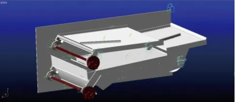
The overall balance model of the oscillating sieve and the return pan is shown in Figure 19. When the overall balance is taken into account, the counterweight of the oscillating sieve can be reduced because of the offset of the inertial force from the return pan.
When φ=45°, in the counterweight interval (13.9-16.5 kg), seven sets of data were selected as the variable: 13.5 kg, 14.0 kg, 14.5 kg, 15 kg, 15.5 kg, 16 kg and 16.6 kg. The simulation time was 1.0 s, and the step size was 0.01 s. After data processing, the movement track of the total center of mass was obtained (Figure 20). The overall counter-force is shown in Table 3.
Figure 19 Overall balance model in ADAMS
Figure 20 Movement tracks of the mass center under different counterweights
As shown in Table 3, when the counterweight was 15.5 kg, the movement track range of the total mass center was at a minimum and the peak-to-peak value was also at a minimum. Thus, the optimum counterweight of the overall balance was 15.5 kg.
Table 3 Overall inertial forces under different counterweights
Mass/kg Min/N Max/N Mean value/N RMS Peak-to-peak value/N
14.0 1580 2510 1941 1965 930
14.5 1593 2511 1937 1962 918
15 1604 2513 1934 1959 909
15.5 1612 2518 1930 1957 906
16 1592 2523 1927 1956 931
16.5 1568 2530 1925 1954 962
Figure 21 shows that when the overall balance counterweight was 15.5 kg, the movement track range of the mass center was smaller than the movement track range with a 18 kg counterweight, which was the optimum counterweight in the above. It was concluded that, the overall balance not only reduced the counterweight but also made the oscillating sieve and return pan more balanced according to the above method.
Note: In order to make the two parts (15.5 kg and 18.0 kg) contrast more visual and clear, the movement tracks image of 15.5 kg is translated into the position shown in the above graph without changing its shape in the coordinate system.
Figure 21 Comparison of movement tracks under 15.5 kg and 18.0 kg
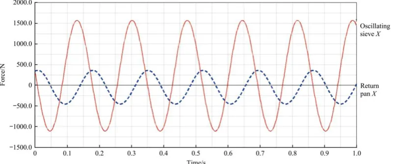
Crank initial angle of the return pan was another important factor in the overall balance when crank initial angles of the oscillating sieve was immutable; different crank initial angles of the return pan will cause different degrees of inertial force offset. According to Figure 22, the main movement of the oscillating sieve and return pan and the inertial force on the frame were mainly in the X direction. With φ=45°, although the inertial force decreased and the counterweight was smaller, the inertial force offset in the X direction was still not ideal and the overall inertial force was relatively large. Therefore, three different crank initial angle (φ=0°, φ=45° and φ=90°) of the return pan were set up in the ADAMS to find the optimum angle that minimize the overall inertia force.
The analysis showed that: when φ=90° (the crank initial angle of the return pan was the same as the crank initial phase of the oscillating sieve), the degree of inertial force offset in the X direction was at a maximum and the overall inertia was at a minimum (Figure 23). Figure 24 showed the different initial angles of the crank of the return pan in ADAMS.
significantly decreased compared with other initial crank angles, demonstrating that the configuration of the initial crank angle of the
oscillating sieve and the return pan at the same position (φ=90°) was the most favorable for reducing the overall inertial force.
Figure 22 Inertial force offset in the X direction of the return pan and oscillating sieve (φ=45°)
Figure 23 Inertial force offset in the X direction of the return pan and oscillating sieve (φ=90°)
Figure 24 Different crank initial angles of the return pan
Figure 25 Overall inertial force under different crank initial angles of the return pan
4 Conclusions
1) The partial equilibrium of the inertial force balance was used to calculate the counterweight intervals of 5.4-6.1 kg for the return pan and 16.0-20.1 kg for the oscillating sieve.
2) The assembled model of the oscillating sieve and return pan were imputed into the ADAMS software individually, and the optimum counterweights were 5.9 kg and 18 kg for the return pan and oscillating sieve, respectively.
4) The configuration of the initial crank angle of the oscillating sieve and the return pan at the same position (φ=90°) was the most reasonable for reducing the overall inertial force.
Acknowledgments
This research was supported by the National Natural Science Foundation of China (51475217), the Fok Ying-Tong Education Foundation of China (Grant No. 141051), Six Talent Peaks Project in Jiangsu Province (NY-024) and a project funded by the Priority Academic Program Development (PAPD) of Jiangsu Higher Education Institutions. We greatly appreciate the anonymous reviewers for their constructive comments that improved our manuscript.
[References]
[1] Steyn J. Fatigue failure of deck support beams on a vibrating screen. International Journal of Pressure Vessels and Piping, 1995; 61(3): 315–327.
[2] Huynh V, Powell T. Threshing and separating process-a mathematical model. Transactions of the ASABE, 1982; 24(1): 65–73.
[3] Wang Q. Research on inertial force balance of the vibrating screen in a combine harvester. Master’s thesis. Chengdu: Xihua University, 2013; 63p. (in Chinese)
[4] Yu Y Q, Li Z. Modern mechanical dynamics. Beijing: Beijing University of Technology University Press, 1998; pp.32–65. (in Chinese)
[5] Zhang H T. Research on the kinematics and inertial force balance of the vibrating screen. Master’s thesis. Sichuan: Xihua University, 2011; 51p. (in Chinese)
[6] Zhang H T, Li X H. Research on the balance effect of shaker used in combine harvester. Mechanical Research and Application, 2011; 23(1): 63–64. (in Chinese)
[7] Caudhary K, Chaudhary H. Optimum balancing of slider-crank mechanism using equimomental system of point-masses. Journal of Mechanical Science and Technology, 2015; 29(12): 5189–5198.
[8] Aakelian V, Briot S. Simultaneous inertia force/moment balancing and torque compensation of slider-crank mechanisms. Mechanics Research Communications, 2010; 37: 265–269.
[9] Guarnieri A, Maglioni C, Molari G. Dynamic analysis of reciprocating single-blade cutter bars. Transactions of the ASABE, 2007; 50(3): 755–764. [10] Fukushima T, Inoue E, Mitsuoka M, Okayasu T, Sato K. Collision
vibration characteristics with interspace in knife driving system of combine harvester. Engineering in Agriculture, Environment and Food, 2012; 5(3): 115–120.
[11] Somchai C U. Development of a cutter bar driver for reduction of vibration for a rice combine harvester. KKU Research, 2010; 15(7): 572–580.
[12] Li X L, Wang Q, Zhang X Q. Finite element analysis and optimization of vibrating screen rocker. Agricultural Equipment and Vehicle Engineering, 2014; 52(8): 51–54. (in Chinese)
[13] Li G, Wang CH, Li Y C, Fang M H. Investigation on inertial force balancing of slider-crank type cleaning sieve. Journal of Agricultural Mechanization Research, 2016; 38(8): 24–35. (in Chinese)
[14] Xu L Z, Li Y M, Wang C H, Xue Z. A combinational threshing and separating unit of combine harvester with a transverse tangential cylinder and axial rotor. Transactions of the CSAM, 2014; 45(2): 105–108. (in Chinese)
[15] Li H C, Li Y M, Gao F, Zhao Z, Xu L Z. CFD–DEM simulation of material motion in air-and-screen cleaning device. Computers and Electronics in Agriculture, 2012; 88(10): 111–119.
[16] Mekonnen G. Numerical and experimental study of a cross-flow fan for combine cleaning shoes. Biosystems Engineering, 2010; 106(4): 448–457. [17] Zhang C. Mechanical kinetics. Beijing: Higher Education Press, 2000;
375p.