Vol.8 (2018) No. 2
ISSN: 2088-5334
Geo-Hydrological Stability Analysis of Fly Ash Stabilised
Overburden Dump Slopes in Opencast Coal Mines Using Finite
Element Analysis
Tushar Gupta
#, T. N. Singh
* #IITB-Monash Research Academy, IIT Bombay, India E-mail: [email protected]
*
Department of Earth Sciences, IIT Bombay, India E-mail: [email protected]
Abstract— Fly ash is one of the major waste line products in coal power sector and simultaneously one of the most desirable products in the construction industry, due to its pozzolanic nature. This has resulted in fly ash being used as a partial replacement of cement and in various composites, for civil and mining industries. Recent studies and applications have shown the viability of fly ash as an economical and eco-friendly stabiliser for dump slopes in opencast mines. Apart from the analysis of structural stability due to the pozzolanic binding nature of fly ash, it is also important to study the hydrological aspects of dump slopes in conjugation with the fly ash stabiliser. This study performs the numerical simulation for the dump slopes using finite element analysis (FEA) for studying the effect of fly ash stabilisation layer on water movement and associated hydrological investigation. The effect of water head build-up (due to fly ash stabilisation layer) on the overall stability of dump slope is analysed and compared to give an estimate for the increase in a factor of safety of slope and a viable dimensional increase of slope geometry. It is seen that fly ash layer stabilisation is effective even in the saturated state of overburden dumps, with the factor of safety increasing from 1.09 to 1.32. Proper drainage channels are found to be essential to prevent any excess stress build-up due to the low permeability of fly ash layers.
Keywords— hydrological analysis; fly ash; composites; dump stabilisation; finite element analysis
I. INTRODUCTION
Surface mining methods arguably give the highest production figures, with better productivity and greater extraction efficiency, as compared to most of the other mining methods. Close to 85% of Indian coal comes from surface coal mines, which can give some idea of the scale of the surface mining operation [1]. Consequently, at these huge scales of working, there is a foremost requirement of the safety of operation. One of the prime avenues of safety in a mining operation is the stability of the overburden dumps. Due to the limitation of available land space and the huge amounts of overburden that is removed in an average surface mining operation, there is always a requirement to make higher and steeper overburden dumps to accommodate increasingly more material in given land area [2]. Though the dimensions of these dumps are usually regulated by local mining legislation, the size of dumps dictates a major part of mine economics, as even a small degree of change in slope angle can lead to huge cost savings. However, failure of these dumps can cause huge loss of life and property as is seen in various recent and past reported cases [2]-[4]. Hence
it is a vital requirement for a surface mining operation to make safer and stable dump slopes. There are various methods utilised for dump slope stabilisation, which includes mechanical stabilisation [5]-[9], chemical stabilisation [10]-[13] and biological stabilisation [14]-[16]. Among this one of the more economical and ecological options for stabilisation of dumps is using fly ash composite layers as a stabiliser. Fly ash, which is generated in huge quantities as a by-product of coal burning in coal power plants, exhibits a unique characteristic called pozzolanicity. This basically makes fly ash inert in its natural state but exhibits cement like binding property in the presence of any external source of lime [17]. This makes fly ash a good candidate for stabilisation of dumps, especially because traditional stabilisers such as cement, cannot be used due to the economics of mining operations.
dumped in ash ponds and dykes [18]. Hence utilisation of fly ash in mines for dump stabilisation is a much more practical application, which is economical, and environmentally safe. Research in various aspect of applicability of fly ash in overburden dumps have already been conducted, that show increased stability of dump slopes by imbibition of fly ash composites in its construction [19]-[21]. However, hydrological aspects of stabilisation of fly ash composite layers have not been studied. Since water accumulation and related instabilities are also an important aspect of slope stabilisation, this paper studies these hydrological aspects of fly ash utilisation in these dump slopes. Numerical simulation modelling is done using finite element analysis. A comparative investigation is presented here, which gives a clear perspective of the hydrological statics and kinetics in overburden dumps, and the effect of fly ash composite stabilisation on the same.
II. MATERIAL AND METHODS
A. Lab Studies and Previous Work
For stabilisation operation by fly ash, a composite comprising of fly ash, lime and overburden were formulated. The composition of each constituent was optimised for obtaining the maximum strength of the composite. A detailed physical and chemical characterisation of fly ash, lime (hydrated lime) and overburden material was first performed in laboratory by a series of experiments like Sieve analysis, XRD and XRF analysis (Table 1), SEM imaging (Fig. 1) and tests for optimum moisture content, maximum dry density, liquid limit, and plastic limit. The components were then mixed in varying proportions, and cubical samples were made and kept for definite curing periods in high humidity environment (Fig. 2). These cubical samples were then tested for their strength and other geotechnical properties to obtain the optimum composition [17].
Fig. 1 Scanning Electron Microscopic images of (a) Fly ash cenosphere, (b) Slacked lime particles and (c) Silica Particle(Low magnification), the components of fly ash composite.
TABLEI
XRDANALYSIS RESULTS OF FLY ASH,SLACKED LIME, AND OVERBURDEN MATERIAL
Components (%) Fly Ash Lime Overburden
Al2O3 17.52 0.01 5.62
CaO/ Ca(OH)2 0.42 97.82 0.02
Fe2O3 1.86 0 1.56
MgO 1.7 0 0
K2O 0.26 0.05 0.06
SiO2 38.98 1.25 84.25
TiO2 1.56 0 0
P2O5 0.44 0 0
Na2O 0.32 0.09 0.56
Fig. 2 Schematic of the experimentation, including moulding of composite (top left), curing of samples (top right), testing of samples for geotechnical properties (bottom left and right)
Numerical simulation analysis was performed to judge the applicability of the obtained fly ash composite in the stabilisation of overburden dumps. There were two scenarios that were analysed using fly ash in dump stabilisation. The first, where the whole of the dump was evenly made with a mixture of ash composite, and the second, where layers of high strength ash composite were used as stabilisation layers (Fig. 3) [17]. Detailed analysis using finite element approach showed that the most appropriate design of such dumps would be the fly ash layered design which gave a much better factor of safety (a parameter to judge the safety of slope or any other structure) than the other design [21]. For our present study, the layered design will be used for analysis purpose.
Fig. 3 Two proposed stability models (a) the whole dump is of fly ash stabilised overburden, (b) Bands of fly ash composite in overburden
B. Stability Problems by Water
One of the important factors for dump slope stability that is often overlooked is the effect of water. Overburden is majorly blasted out rock and soil, which is generally highly porous in nature due to the end-dumping techniques. This results in easy percolation of water through the dump to its lower layers, which may result in accumulation of water if proper drainage routes are not made. Accumulation of water in dumps can be disastrous and can lead to massive failures of dump slope as was seen in 2008 in the western section of Jayant opencast mine [22].
creates pore pressure, which is the force of water present in voids of the overburden material. This pressure can be both positive (forcing the overburden particles away from each other) or negative (in the form of suction/ capillary pressure), and hence changes the dynamics of slope stability. Thirdly, oversaturation of water makes the particles loose due to dilution, which changes the internal properties of overburden material such as cohesion and internal angle of friction, hence causing instability in an originally stable slope. Though proper drainage channels generally prevent the accumulation of water, these become ineffective with time due to the build-up of fine soil at the base of dumps, transported from infiltration of rainwater over time [23].
Infiltration, therefore, becomes an important aspect to be analysed for dump slope stability analysis. In our model, where the overburden dump is stabilised by fly ash layers, this analysis becomes more complex. The fly ash composite that is used for stabilisation here has very low permeability and hydraulic conductivity values (~ 10e-9 m/s) and is very less porous as compared to the overburden material. This effectively makes it a sill, that is very less permeable, and hence, water accumulation can take place over the composite layers. However, since it may work as a sill, the accumulation of water at the base will be less, and that can lead to higher stability and resistance against hydrological failures. The following analysis is an effort to understand these phenomena with the help of finite element modelling.
C. Numerical Simulation Model
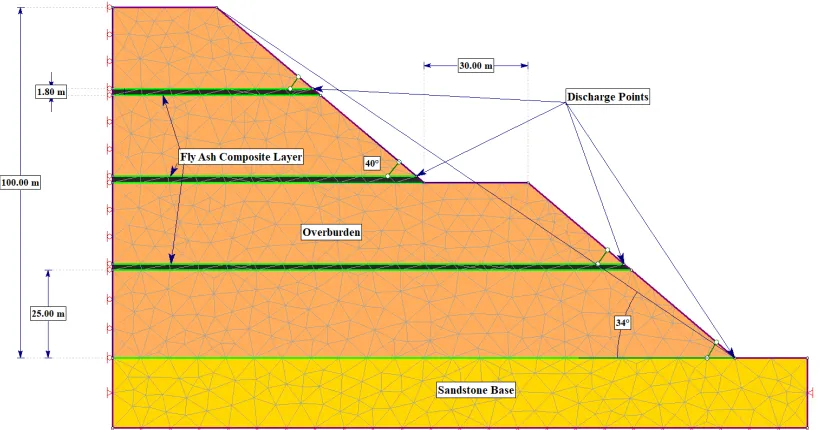
A numerical model using Phase-2 software was made, replicating the analysis performed in previous studies [21]. The model is a two-bench dump, with a total height of 100m. The berm width is left to be 30m (assuming it was also being used as dump road), keeping an effective overall slope angle of 34°. Three horizontal layers of fly ash, separated from the base and with each other by 25 m, are stabilising the whole dump (Fig. 4). The thickness of these layers was optimised
for this configuration at 1.8m [21]. A comparative model with no fly-ash layer is also analysed for simulation purpose. The toe of the dump, as well as the top edges of the fly ash layers, are taken as discharge locations (Fig. 4). These are forced open and close to see the hydrological stresses involved in the model and their effect on overall stability. For the dump with no fly-ash layers, the toe of the dump is the only discharge location. The material properties and hydrological properties were obtained from lab experiments in previous studies. The same was used in this numerical model.
III.RESULTS AND ANALYSIS
The simulation was undertaken in two phases, considering both the hydrostatic state of dump slopes, as well as the infiltration of water through rain. The first phase was a comparative study of the saturated dump slopes, with and without fly ash stabilisation layer. The comparison was made in between the principal stress that was built up due to the dump load, as well as the hydrostatic pressure due to overburden saturation. Fig. 5 shows how the maximum principal stress (σ1) varies for both the dump slopes. For this case of analysis, all the discharge points were closed, and the water was allowed to saturate the whole dump. The analysis shows that effective principle stress was much higher in case of the dump with no stabilisation (with a maximum principal stress of 2.63 MPa), while for the stabilised dumps, the hydrostatic head was well distributed between the fly ash layers, which acted as sills and hence effectively reducing dump to one fourth of its height (a maximum principal stress of 1.98 MPa). The stress is comparatively less at the lower bench of the dump in case of the stabilised dump, as is shown in Fig. 5. This proves the effectiveness of fly ash stabilisation in layer format, for structural, as well as hydrostatic forces. The overall factor of safety also increased from 1.09 in case of non-stabilisation to, 1.32 in case of stabilisation by fly ash layers.
Fig. 5 Comparison between maximum principal stress in the saturated state of non-stabilised (left) and stabilised dump slopes. (right) The solid dot represents a closed discharged point
For the second phase of analysis, a heavy rainfall, at a vertical infiltration rate of 40mm/hr, was simulated. In this case, firstly a comparison was made between the stabilised and the non-stabilised dump slopes by opening only the toe discharge point for water discharge. Since this analysis is static in nature, the results are obtained only when a steady state of water flow and saturation is achieved during the course of the simulation. Fig. 6 shows a comparative study of the above-mentioned cases, in the form of maximum shear strain profile of overburden dump, as well as the water movement. It is seen that for the case of the non-stabilised dump, the maximum shear strain peaks at toe with a value of 0.83. This dump also gives a high volumetric discharge of water giving a high flow rate of 6.84 m3/h from the toe discharge point at steady state. Comparatively, the stabilised slope has a relatively less maximum shear strain of 0.18 at its toe region. However, a higher shear strain is seen at the upper edges of each fly ash layer (0.47, 0.68, 0.41, from top to bottom), which are still comparatively less as compared to non-stabilised dump slopes. These higher values at edges of fly ash layers are attributed to the restriction of overburden material movement due to the higher strength of fly ash layers. As for the water movement in stabilised dump slopes, at the steady state, the movement of water is seen from the exposed part of the bench below the first fly ash layer, with a discharge rate of 6.10 m3/h. The difference in flow rates from discharge point and the restriction in water flow direction can be attributed to the almost impermeable nature of fly ash composite layers. This is also an additional reason for stress build-up at the upper ends of fly ash layers.
The next set of analysis was performed to develop an understanding of the hydrological movement when multiple discharge points are opened. The discharge points were opened progressively from the bottommost toe point till the topmost layer. The effect of the same was seen on maximum shear strain, discharge flow rate, and direction of hydrological movement (Fig. 7). It was observed that the fly ash layers basically divided the whole dump into individual hydrological sections, separated by a highly impervious layer (of fly ash composite). As the discharge points in each section are opened, the stress that was built up while infiltration, due to saturation of water, is released and water mostly takes the route to the nearest discharge points. (Fig. 7).
As is seen in Fig. 7, maximum shear strain reduces from model 7(a) to model 7(d), due to the pressure release from the opening of each successive discharge point. As more number of discharge points are opened, the slope becomes more stable due to decreased stresses and non-accumulation of water. However, as is seen in Fig. 7(d), when all discharge points are opened, there is an increase in shear strain at the top end of the topmost fly ash layer. This was against the expected results, as the nearest discharge point is already open, and there is apparently no reason for additional stress. The reason behind this may be the fact that the total infiltration of rainwater on the topmost section of stabilised dump (the region above the topmost fly ash layer) is many times high as compared to other sections since in those cases, only a part of the slope is exposed for direct infiltration.
(a)
(b)
(c)
(d)
Fig. 7 Maximum shear strain profile and water flow directions, for the progressive opening of water discharge points with (a) only toe discharge open, (b) toe and first fly ash layer discharge open, (c) toe and first two fly ash layer discharge open & (d) all discharge points open. The solid dot represents a closed discharged point, while hollow dot represents an open discharge point
Hence this section handles huge quantities of water transmission when the topmost discharge point is open. This creates a partial oversaturation state, and additional stresses due to heavy fluid flow result in high shear strain, as is seen in Fig. 7(d). The water flow was as expected, and is seen to move towards the discharge points. However, during the successive opening of discharge points, higher amounts of infiltrated water passes through the overburden in the corresponding section (Fig. 7). The rate of discharge for individual section increases rapidly on the opening of discharge section but then reduces as more discharge points are opened higher up the dump.
A plot giving the values of discharge from all the discharge sections, along with the discharge section opening timeline, is presented here (Fig. 8). This gives a clear
indication of the response of water flow on discharge openings. The flow of water is seen to increase as we go from top to bottom, which is not in accordance with normal Darcy’s flow. This is basically because, as we go up the slope of the dump, higher effective infiltration by the rainwater is observed. This results in higher water accumulation, resulting in higher discharge values. This is clearly reflected by the bigger jumps between discharge values at first discharge point when only toe discharge point is opened, and the discharge at the second discharge point, when the bottom two discharge points are opened. A similar jump is seen in between third discharge point at bottom three open discharge points, and the topmost discharge point when all of them are opened.
0 0.002 0.004 0.006 0.008 0.01 0.012
0 1 2 3 4
D
is
c
h
a
rg
e
d
w
a
te
r
in
m
3
/s
Discharge Point opening timeline (counting from bottom to top)
Discharge Point 1 Discharge Point 2 Discharge Point 3 Discharge Point 4
IV.CONCLUSIONS
A critical geo-hydrological investigation was performed for analysing the effect of water movement and accumulation on the overburden dump slope stability.
Following were the conclusions obtained from the study. The fly ash layer type stabilisation for mine overburden dumps is also applicable for saturated soils and overburden material. It was seen that the stress due to such saturation is much more for unestablished dumps. Though the fly ash layer stabilisation is effective, in heavy rain conditions, additional stresses may develop due to water accumulation over the fly ash layers since they have very low permeability. In these cases, it is advisable to have discharge trenches that can drain off the accumulated water to prevent any loss in stability during heavy rains. During rains, the water flow from top trenches will be much more than the bottom ones. Hence effective drainage design is to be conceptualised to handle the amounts of water.
Some future work for this analysis may include the effect of the nearby water body and some dynamic hydrological analysis.
REFERENCES
[1] Prasad, M., Underground coal mining: The way ahead, in Project Monitor. 2009.
[2] Rai, R., et al., Sensitivity analysis of internal dragline dump stability: Finite element analysis. Geotechnical and Geological Engineering, 2012. 30(6): p. 1397-1404.
[3] Bowman, P. and H. Gilchrist. Waste dump instability and its operational impact for a Canadian Plains lignite mine. in Proceedings of the international symposium on stability in coal mining. Vancouver, British Colombia, Canada. 1978.
[4] Kainthola, A., et al., A coal mine dump stability analysis—a case study. Geomaterials, 2011. 1(01): p. 1.
[5] Lersow, M., Deep soil compaction as a method of ground improvement and to stabilization of wastes and slopes with danger of liquefaction, determining the modulus of deformation and shear strength parameters of loose rock. Waste Management, 2001. 21: p. 161-174.
[6] Li, Q., et al., Analysis of the Blasting Compaction on Gravel Soil. Journal of Chemistry, 2015. 2015: p. 1-9.
[7] Olufowobj, I., et al., Clay Soil Stabilisation Using Powdered Glass. Journal of Engineering Science and Technology, 2014. 9(5): p. 541-558.
[8] Clegg, B., Kneading compaction. Australian Road Research, 1964. [9] Geosimpro, Static Weight Compaction. 2017.
[10] Maaitah, O.N., Soil Stabilization by Chemical Agent. Geotechnical and Geological Engineering, 2012. 30(6): p. 1345-1356.
[11] Hamzah, H.N., et al., Review of Soil Stabilization Techniques: Geopolymerization Method one of the New Technique. Key Engineering Materials, 2015. 660: p. 298-304.
[12] Karatai, T.R., et al., Soil Stabilization Using Rice Husk Ash and Natural Lime as an Alternative to Cutting and Filling in Road Construction. Journal of Construction Engineering and Management, 2016: p. 04016127.
[13] Onyejekwe, S. and G.S. Ghataora, Soil stabilization using proprietary liquid chemical stabilizers: sulphonated oil and a polymer. Bulletin of Engineering Geology and the Environment, 2014. 74(2): p. 651-665.
[14] Calderwood, T., Why is Hydroseeding Better than Traditional Methods of Growing Lawns? 2016, RadioYu.
[15] Shahram, P., et al., Application of Alkali-Activated Agro-Waste Reinforced with Wollastonite Fibers in Soil Stabilization. Journal of Materials in Civil Engineering, 2017. 29(2).
[16] Nguyen, L., Fibre reinforced clay, U.r.g.u.s.a. carpeting, Editor. 2014, CRICOS: UTS Newsroom.
[17] Gupta, T., S.P. Pradhan, and T.N. Singh. A Critical Study on Feasibility of Fly Ash Utilization in Overburden Dumps of Opencast Coal Mines. in Seminar on Sustainable Development in Mineral & Earth Resources. 2014. New Delhi: The Indian Mining & Engineering Journal.
[18] CEA, Fly ash generation at coal/lignite based thermal power stations and its utilization in the country for the year 2014-15. 2016, Central Electricity Authority: New delhi.
[19] Nayak, T., Stability analysis of dump with admixture of fly-ash and overburden material in open-cast coal mines. 2013, NIT Rourkela. [20] Gupta, A.K. and B. Paul, Augmenting the Stability of OB Dump by
Using Fly Ash: A Geo Technical Approach to Sustainably Manage OB Dump at Jharia Coal Field, India. Current World Environment, 2016. 11(1): p. 204.
[21] Gupta, T., M. Yellishetty, and T. Singh, Optimization of ash content in overburden dumps: A numerical approach, in Proceedings of MPES 2015-Smart Innovation in Mining. 2015, The Southern African Institute of Mining and Metallurgy Johannesburg, South Africa. p. 997-1004.
[22] Sharma, S. and I. Roy, Slope Failure Of Waste Rock Dump At Jayant Opencast Mine, India: A Case Study. International Journal of Applied Engineering Research, 2015. 10(13).