1 .
Alpha
Contributing Authors Richard Witek
Alpha co-architect
and
Ellen M. Batbouta Richard A. Brunner Wayne M. Cardoza Daniel W. Dobberpuhl Robert A. Giggi Henry N. Grieb Richard B. Grove Robert H. Halstead, Jr. Michael S. Harvey Nancy P. Kronenberg Raymond J. Lanza Stephen J. Morris William B. Noyce Charl~sG. Nylander Mary H. Payne Audrey R. Reith Robert M. Supnik Benjamin J. Thomas Catharine Van Ingen
~DmDDmD
Alpha
Architecture
Reference
Manual
Edited by
Richard L. Sites
Alpha co-architect
Copyright©1992 by Digital Equipment Corporation
All rights reserved. No part of this publication may be reproduced, stored in a retrieval system, or transmitted, in any form or by any means, electronic, mechanical, photocopying, recording, or otherwise, without prior written permission of the publisher.
Printed in the United States of America.
9876543
Order number EY-L520E-DP ISBN I-55558-098-X
Technical Writer: Charles Greenman Production Editor: Kathe Rhoades Technical Illustrator: Lynne Kenison Cover Design: Marshall Henrichs
The following are trademarks of Digital Equipment Corporation: Alpha AXP, AXP, the AXP logo, DEC, the Digital logo, OpenVMS, PALcode, PDP-II, VAX, VMS, and ULTRIX. Cray is a registered trademark of Cray Research, Inc. IBM is a registered trademark of International Business Machines Corporation. OSF/I is a registered trademark of Open Software Foundation, Inc. UNIX. is a registered trademark of UNIX. System Laboratories, Inc.
Foreword Preface
Part
II
Common Architecture
1 Introduction 2 Basic Architecture 3 Instruction Formats 4 Instruction Descriptions
5 System Architecture and Programming Implications 6 Common PALcode Architecture
7 Console Subsystem Overview 8 Input/Output
Part III OpenVMS Alpha Software
1 Introduction to OpenVMS Alpha
2 OpenVMS PALcode Instruction Descriptions 3 OpenVMS Memory Management
4 OpenVMS Process Structure
5 OpenVMS Internal Processor Registers
6 OpenVMS Exceptions, Interrupts, and Machine Checks
Part III1 DEC
OSF/1
Alpha Software
1 Introduction to DEC OSF/l Alpha 2 OSF/l PALcode Instruction Descriptions 3 OSF/l Memory Management
4 OSF/l Process Structure
5 OSF/l Exceptions and Interrupts
Appendixes
A Software Considerations
B IEEE Floating-Point Conformance C Instruction Encodings
Index
NOTE
The final name of the architecture had not been formalized at the first printing of the Alpha Architecture Reference Manual.. The final name has now been determined and it is Alpha AXP. Therefore, all references in this manual to the Alpha architecture mean the Alpha AXP architecture.
Foreword
In the foreword to theVAX Architecture Reference Manual, Sam Fuller, Digital's Vice
President for Research and Architecture, wrote, "Computer design continues to be a dynamic field; I expect we will see more rather than less change and innovation in the decades ahead."The Alpha Architecture Reference Manual demonstrates the
accuracy of that prediction.
Alpha follows VAX by about fifteen years. Those fifteen years have witnessed a torrent of change in computer technology, one that shows no sign of abating:
• More than a 1000-fold increase in the performance of microprocessors
• More than a 1000-fold increase in the density of semiconductor memories
• More than a 500-fold increase in the density of magnetic storage devices
• More than a 100-fold increase in the speed of network connections
During the same period, the internal organization of computer systems has changed as well, based on developments such as RISC architecture, symmetric multipro-cessing, and coherent distributed systems. Moreover, the fundamental paradigms of computing have changed not once, but several times, with the introduction of personal computers, graphics workstations, local area networks, and client/server computing.
These developments present an enormous challenge for computing in the 21st cen-tury. Future computers will be called upon to solve problems of great scale and complexity, worldwide, in a distributed manner. They will have to provide unprece-dented performance, flexibility, reliability, and scalability in order to implement a global infrastructure of information, and to give users an untrammeled window on the world.
Alpha is Digital's response to the challenges of 21st-century computing. It represents the culmination of the company's knowledge and belief about how the next genera-tions of computers should be built. Alpha is based on a decade's experimental and engineering work in RISe architecture, high-speed implementation, software com-patibility and migration, and system serviceability. It provides the foundation for implementations ranging from mobile computing units to massively parallel super-computers.
of the gigabytes and terabytes of data producedinelectrical and mechanical design, database and transaction processing, and imaging.
Second, Alpha is a RISe architecture; VAX is a CISC architecture. RISC stands for Reduced Instruction Set Computer, CISC for Complex Instruction Set Computer. RISC architectures are characterized by simple, fixed-length instruction formats; a small number of addressing modes; large register files; a load-store instruction set model; and direct hardware execution of instructions. CISC architectures are characterized by variable-length instruction formats; a large number of addressing modes; small-to-medium-sized register files; a full set of register-to-memory (or even memory-to-memory) instructions; and microcoded execution of instructions. Alpha's streamlined organization facilitates high-speed implementation in a variety of technologies, while providing strong compatibility with today's programs and data.
The following tabulation contrasts the architectural differences between VAX and Alpha:
Architecture
Virtual address range Physical address range Page size
Instruction lengths General registers Addressing modes
Instruction set architecture Directly supported data types
VAX
CISC 32 bits Upto32 bits 512bytes 1-51bytes 16x32 bits 21
General
Integer, floating, bit field, queue, character string, decimal string
Alpha
RISC Upto64bits Upto48bits 8KB--64KB
4bytes
64x64bits 3
Load-store Integer, floating
This book is the culmination of an effort begun three years ago. In that time, Alpha has grown from a paper specification to a cohesive set of chips, systems, and software, spanning the computer spectrum. This achievement is due to the efforts of many hundreds of people in Engineering, Marketing, Sales, Service, and Manufacturing. This book is documentation of, and a tribute to, the outstanding work they have done.
Bob Supnik
Preface
The Alpha architecture is a RISC architecture that was designed for high per-formance and longevity. Following Amdahl, Blaauw, and Brooks,! we distinguish between architecture and implementation:
• Computer architecture is defined as the attributes of a computer seen by a machine-language programmer. This definition includes the instruction set, instruction formats, operation codes, addressing modes, and all registers and memory locations that may be directly manipulated by a machine-language programmer.
• Implementation is defined as the actual hardware structure, logic design, and data-path organization.
This architecture book describes the required behavior of all Alpha implementations, as seen by the machine-language programmer. The architecture does not speakto implementation considerations such has how fast a program runs, what specific bit pattern is left in a hardware register after an unpredictable operation, how to schedule code for a particular chip, or how to wire up a given chip; those considerations are described in implementation-specific documents.
Various Alpha implementations are expected over the coming years, starting with the Digital 21064 chip.
Goals
When we started the Alpha project in the fall of 1988, we had a small number of goals:
1. High performance
2. Longevity
3. Run VMS and UNIX
4. Easy migration from VAX (and soon-to-be MIPS) customer base
As principal architects, Rich Witek and I made design decisions that were driven directly by these goals.
We assumed that high performance was needed to make a new architecture attractive in the marketplace, and to keep Digital competitive.
We set a 15-25 year design horizon (longevity) and triedtoavoid any design elements that we thought would become limitations during this time. The design horizon led directly to the conclusion that Alpha could not be a bit architecture: 32-bit addresses will be too small within 10 years. We thus adopted a full 64-32-bit
architecture, with a minimal number of 32-bit operations for backward compatibility. Wherever possible, 32-bit operands are put in registers in a 64-bit canonical form and operated upon with 64-bit operations.
The longevity goal also caused us to examine how the performance of implementa-tions would scale up over 25 years. Over the past 25 years, computers have become about 1000 times faster. This suggested to us that Alpha implementations would need to do the same, or we would have to bet that the industry would falloff the historical performance curve. We were unwilling to bet against the industry, and were unwilling to ignore the issue, so we seriously examined the consequences of longevity.
We thought that it would be realistic for implementors to improve clock speeds by a factor of 10 over 25 years, but not by a factor of 100 or 1000. (Clock speeds have improved by about a factor of100 over the past 25 years, but physical limits are now slowing down the rate of increase.)
We concluded that the remaining factor of 100 would have to come from other design dimensions. If you cannot make the clock faster, the next dimension is to do more work per clock cycle. So the Alpha architecture is focused on allowing implementations that issue many instructions every clock cycle. We thought that it would be realistic for implementors to achieve about a factor of 10 over 25 years by using multiple instruction issue, but not a factor of 100. Even a factor of 10 will require perhaps a decade of compiler research.
We concluded that the remaining factor of 10 would have to come from some other design dimension. If you cannot make the clock faster, and cannot do more work per clock, the next dimension is to have multiple clocked instruction streams, that is, multiple processors. So the Alpha architecture is focused on allowing implementa-tions that apply multiple processors to a single problem. We thought that it would be realistic for implementors to achieve the remaining factor of 10 over 25 years by using multiple processors.
Overall, the factor-of-l000 increase in performance looked reasonable, but required factor-of-10 increases in three different dimensions. These three dimensions therefore formed part of our design framework:
• Gracefully allow fast cycle-time implementations
• Gracefully allow multiple-instruction-issue implementations
• Gracefully allow multiple-processor implementations
The cycle-time goal encouraged us to keep the instruction definitions very simple, and to keep the interactions between instructions very simple. The multiple-instruction-issue goal encouraged us to eliminate specialized registers, architected delay slots, precise arithmetic traps, and byte writes (with their embedded read-modify-write bottleneck). The multiple-processor goal encouraged us to consider the memory model and atomic-update primitives carefully. We adopted load-Iockedlstore-conditional sequences as the atomic-update primitive, and eliminated strict read-write ordering between processors.
longevity goals. The lack of byte writes, precise arithmetic traps, and multiprocessor read/write ordering have been the most controversial decisions, so far.
Clean Sheet of Paper
To run both OpenVMS and UNIX without burdening the hardware implementa-tions with elaborate (and sometimes conflicting) operating system underpinnings, we adopted an idea from a previous Digital RISC design. Alpha places the under-pinnings for interrupt delivery and return, exceptions, context switching, memory management, and error handling in a set of privileged software subroutines called PALcode (privileged architecture library code). PALcode subroutines have controlled entries, run with interrupts turned off, and have access to real hardware (implemen-tation) registers. By having different sets of PALcode for different operating systems, the architecture itself is not biased toward a specific operating system or computing style.
PALcode allowed us to design an architecture that could run OpenVMS gracefully without elaborate hardware and without massively rewriting the VMS synchroniza-tion and protecsynchroniza-tion mechanisms. PALcode lets the Alpha architecture support some complex VAX primitives (such as the interlocked queue instructions) that are heavily used by OpenVMS, without burdening a UNIX implementation in any way.
Finally, we also considered how to move VAX and MIPS code to Alpha. We rejected various forms of "compatibility mode" hardware, because they would have severely compromised the performance and time-to-market of the first implementation. After some experimentation, we adopted the strategy of running existing binary code by building software translators. One translator converts OpenVMS VAX images to functionally identical OpenVMS Alpha images. A second translator converts MIPS ULTRIX images to functionally identical DEC OSF/l Alpha images.
Fundamentally, PALcode gave us a migration path for existing operating systems, and the translators (and native compilers) gave us a migration path for existing user-mode code. PALcode and the translators provided a clean sheet of design paper for the bulk of the Alpha architecture. Other than an extra set of VAX floating-point formats (included for good business reasons, but subsettable later), no specific VAX or MIPS features are carried directly into the Alpha architecture for compatibility reasons.
These considerations substantially shaped the architecture described in the rest of this book.
Organization
The first part of this book describes the instruction-set architecture, and is largely self-contained for readers who are involved with compilers or with assembly language programming. The second and third parts describe the supporting PALcode routines for each operating system-the specific operating system PALcode architecture.
Acknowledgments
A work of this magnitude cannot be done on a shoestring or in isolation. Rich and I were blessed with a rich environment of dozens and later hundreds of bright, thoughtful, and outspoken professional peers. I thank the management of Digital Equipment Corporation for providing that rich environment, and those peers for making the architecture so much more robust and well-considered.
Three people have especially influenced my views of computer architecture, through personal interaction and landmark machine design: Fred Brooks, John Cocke, and Seymour Cray. This work is built directly upon theirs, and could not exist without them.
The organization, editing, and production of this text in final form is largely the work of Charlie Greenman, whose clear writing is much appreciated.
A Note on the Structure of This Book
The Alpha Architecture Reference Manual is divided into three parts, three ap-pendixes, and an index. Each part describes a major portion of the Alpha architecture. Each contains its own table of contents.
The following tabulation outlines the book's contents:
Name
Part I
Part II
Part III
Appendixes
Index
Contents
Common Architecture
This part describes the instruction-set architecture that is common to and required by all implementations.
OpenVMS Alpha Software
This part describes how the OpenVMS operating system relates to the Alpha architecture.
DEC OSF/l Alpha Software
This part describes how the DEC OSF/l operating system relates to the Alpha architecture.
The appendixes describe implementation considerations, IEEE floating-point conformance, and instruction encodings.
Part I
Common Architecture
This part describes the common Alpha architecture and contains the following chapters:
1. Introduction
2. Basic Architecture
3. Instruction Formats
4. Instruction Descriptions
5. System Architecture and Programming Implications
6. Common PALcode Architecture
7. Console Subsystem Overview
8. Input/Output
Contents
Common Architecture (I)
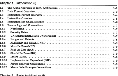
Chapter 1 Introduction (I)
1.1 The Alpha Approach to RISe Architecture 1-1
1.2 Data Format Overview. . . 1-3 1.3 Instruction Format Overview. . . 1-4 1.4 Instruction Overview. . . 1-5
1.5 Instruction Set Characteristics 1-6
1.6 Terminology and Conventions 1-7
1.6.1 Numbering. . . 1-7 1.6.2 Security Holes . . . 1-7 1.6.3 UNPREDICTABLE and UNDEFINED.. .. . .. .. . . .. .. . . .. . . .. . . . 1-7 1.6.4 Ranges and Extents. . . 1-8 1.6.5 ALIGNED and UNALIGNED. .. .. .. .. .. . . .. . .. . . 1-8
1.6.6 Must Be Zero (MBZ) 1-9
1.6.7 ReadAsZero (RAZ) . . . 1-9 1.6.8 Should Be Zero (SBZ). . . 1-9 1.6.9 Ignore (IGN). . . 1-9 1.6.10 Implementation Dependent (IMP) . . . 1-9 1.6.11 Figure Drawing Conventions. . . 1-9 1.6.12 Macro Code Example Conventions. . . 1-9
Chapter 2 Basic Architecture (I)
2.1 Addressing. . . 2-1 2.2 Data 'IY'Pes . . . 2-1 2.2.1 Byte . . . 2-1 2.2.2 Word. . . 2-1 2.2.3 Longword . . . 2-2 2.2.4 Quadword. . . 2-2
2.2.5 VAX Floating-Point Formats 2-3
2.2.5.1 F_floating. . . 2-3 2.2.5.2 G_floating. . . 2-5 2.2.5.3 D_floating. . . 2-6
2.2.6 IEEE Floating-Point Formats 2-7
2.2.6.1 S_Floating . . . 2-8 2.2.6.2 T_floating. . . .. 2-10
[image:18.514.58.463.168.431.2]2.2.7 2.2.8 2.2.9
Longword Integer Format in Floating-Point Unit .
Quadword Integer Format in Floating-Point Unit .
Data Types with No Hardware Support .
2-11 2-12 2-13
Chapter 3 Instruction Formats (I)
3.1 Alpha Registers. . . 3-1 3.1.1 Program Counter. . . 3-1 3.1.2 Integer Registers. . . 3-1 3.1.3 Floating-Point Registers. . . 3-2 3.1.4 Lock Registers. . . 3-2 3.1.5 Optional Registers . . . 3-2
3.1.5.1 Memory Prefetch Registers 3-2
3.1.5.2 VAX Compatibility Register. . . 3-2 3.2 Notation. . . 3-2
3.2.1 Operand Notation 3-3
3.2.2 Instruction Operand Notation .. . . 3--4 3.2.3 Operators. . . 3-5 3.2.4 Notation Conventions. . . 3-8 3.3 Instruction Formats . . . 3-8 3.3.1 Memory Instruction Format. . . 3-9 3.3.1.1 Memory Format Instructions with a Function Code. . . 3-9 3.3.1.2 Memory Format Jump Instructions. . . .. 3-10
3.3.2 Branch Instruction Format 3-10
3.3.3 Operate Instruction Format. . . .. 3-10 3.3.4 Floating-Point Operate Instruction Format . . . .. 3-12 3.3.4.1 Floating-Point Convert Instructions. . . .. 3-12
3.3.5 PALcode Instruction Format 3-13
Chapter 4 Instruction Descriptions (I)
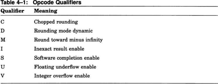
4.1 Instruction Set Overview. . . 4-1
4.1.1 Subsetting Rules 4-2
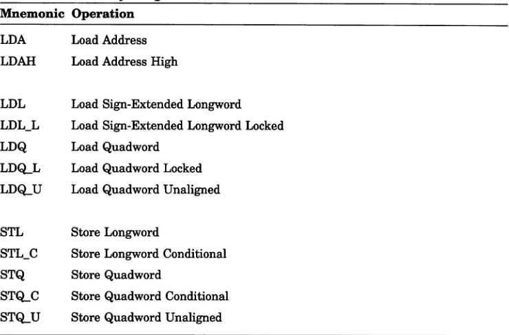
4.1.1.1 Floating-Point Subsets. . . 4-2 4.1.2 Software Emulation Rules. . . 4-2 4.1.3 Opcode Qualifiers. . . 4-3 4.2 Memory Integer Load/Store Instructions . . . 4-4 4.2.1 Load Address . . . 4-5 4.2.2 Load Memory Data into Integer Register. . . 4-6 4.2.3 Load Unaligned Memory Data into Integer Register. . . 4-7 4.2.4 Load Memory Data into Integer Register Locked. . . 4-8 4.2.5 Store Integer Register Data into Memory Conditional. . . .. 4-11
4.2.6 Store Integer Register Data into Memory 4-13
4.3.1 Conditional Branch .
4.3.2 Unconditional Branch .
4.3.3 Jumps .
4.4 Integer Arithmetic Instructions .
4.4.1 Longword Add .
4.4.2 Scaled Longword Add .
4.4.3 Quadword Add .
4.4.4 Scaled Quadword Add .
4.4.5 Integer Signed Compare .
4.4.6 Integer Unsigned Compare .
4.4.7 Longword Multiply .
4.4.8 Quadword Multiply .
4.4.9 Unsigned Quadword Multiply High .
4.4.10 Longword Subtract .
4.4.11 Scaled Longword Subtract .
4.4.12 Quadword Subtract .
4.4.13 Scaled Quadword Subtract .
4.5 Logical and Shift Instructions .
4.5.1 Logical Functions .
4.5.2 Conditional Move Integer .
4.5.3 Shift Logical .
4.5.4 Shift Arithmetic .
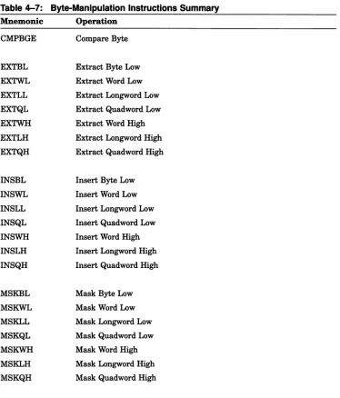
4.6 Byte-Manipulation Instructions .
4.6.1 Compare Byte .
4.6.2 Extract Byte .
4.6.3 Byte Insert .
4.6.4 Byte Mask .
4.6.5 Zero Bytes .
4.7 Floating-Point Instructions .
4.7.1 Floating Subsets and Floating Faults .
4.7.2 Definitions . . . .
4.7.3 Encodings .
4.7.4 Floating-Point Rounding Modes .
4.7.5 Floating-Point Trapping Modes .
4.7.5.1 Imprecise /Software Completion Trap Modes .
4.7.5.2 Invalid Operation Arithmetic Trap .
4.7.5.3 Division by Zero Arithmetic Trap .
4.7.5.4 Overflow Arithmetic Trap .
4.7.5.5 Underflow Arithmetic Trap .
4.7.5.6 Inexact Result Arithmetic Trap .
4.7.5.7 Integer Overflow Arithmetic Trap .
4.7.6 Floating-Point Single-Precision Operations .
4.7.7 FPCR Register and Dynamic Rounding Mode .
4.7.7.1 Accessing the FPCR .
4.7.7.3 Saving and Restoring the FPCR .
4.7.8 IEEE Standard .
4.8 Memory Format Floating-Point Instructions .
4.8.1 Load F_floating .
4.8.2 Load G_floating .
4.8.3 Load S_floating .
4.8.4 Load T_floating .
4.8.5 Store F_floating .
4.8.6 Store G_floating .
4.8.7 Store S_floating .
4.8.8 Store T_floating .
4.9 Branch Format Floating-Point Instructions .
4.9.1 Conditional Branch .
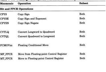
4.10 Floating-Point Operate Format Instructions .
4.10.1 Copy Sign .
4.10.2 Convert Integer to Integer .
4.10.3 Floating-Point Conditional Move .
4.10.4 Move from/to Floating-Point Control Register .
4.10.5 VAX Floating Add .
4.10.6 IEEE Floating Add .
4.10.7 VAX Floating Compare .
4.10.8 IEEE Floating Compare .
4.10.9 Convert VAX Floating to Integer .
4.10.10 Convert Integer to VAX Floating .
4.10.11 Convert VAX Floating to VAX Floating .
4.10.12 Convert IEEE Floating to Integer .
4.10.13 Convert Integer to IEEE Floating .
4.10.14 Convert IEEE Floating to IEEE Floating .
4.10.15 VAX Floating Divide .
4.10.16 IEEE Floating Divide .
4.10.17 VAX Floating Multiply .
4.10.18 IEEE Floating Multiply .
4.10.19 VAX Floating Subtract .
4.10.20 IEEE Floating Subtract .
4.11 Miscellaneous Instructions .
4.11.1 Call Privileged Architecture Library .
4.11.2 Prefetch Data .
4.11.3 Memory Barrier .
4.11.4 Read Process Cycle Counter .
4.11.5 '!rap Barrier .
4.12 VAX Compatibility Instructions .
4.12.1 VAX Compatibility Instructions .
Chapter 5 System Architecture and Programming Implications (I)
5.1 Introduction .
5.2 Physical Memory Behavior .
5.2.1 Coherency of Memory Access .
5.2.2 Granularity of Memory Access .
5.2.3 Width of Memory Access .
5.2.4 Memory-Like Behavior .
5.3 Translation Buffers and Virtual Caches .
5.4 Caches and Write Buffers .
5.5 Data Sharing .
5.5.1 Atomic Change of a Single Datum .
5.5.2 Atomic Update of a Single Datum .
5.5.3 Atomic Update of Data Structures .
5.5.4 Ordering Considerations for Shared Data Structures .
5.6 ReadlWrite Ordering .
5.6.1 Alpha Shared Memory Model .
5.6.1.1 Architectural Definition of Processor Issue Sequence .
5.6.1.2 Definition of Processor Issue Order .
5.6.1.3 Definition of Memory Access Sequence .
5.6.1.4 Definition of Location Access Order .
5.6.1.5 Definition of Storage .
5.6.1.6 Relationship Between Issue Order and Access Order .
5.6.1.7 Definition of Before .
5.6.1.8 Definition of After .
5.6.1.9 Timeliness .
5.6.2 Litmus Tests .
5.6.2.1 Litmus Test1(Impossible Sequence) .
5.6.2.2 Litmus Test2(Impossible Sequence) .
5.6.2.3 Litmus Test3(Impossible Sequence) .
5.6.2.4 Litmus Test4(Sequence Okay) .
5.6.2.5 Litmus Test5(Sequence Okay) .
5.6.2.6 Litmus Test6(Sequence Okay) .
5.6.2.7 Litmus Test7(Impossible Sequence) .
5.6.2.8 Litmus Test8(Impossible Sequence) .
5.6.2.9 Litmus Test9(Impossible Sequence) .
5.6.3 Implied Barriers .
5.6.4 Implications for Software .
5.6.4.1 Single-Processor Data Stream .
5.6.4.2 Single-Processor Instruction Stream .
5.6.4.3 Multiple-Processor Data Stream (Including Single Processor with DMA I/O) . 5.6.4.4 Multiple-Processor Instruction Stream (Including Single Processor with DMA I/O)
5.6.4.5 Multiple-Processor Context Switch .
5.6.4.6 Multiple-Processor SendlReceive Interrupt .
5.6.5 Implications for Hardware .
5.7 Arithmetic '!'.raps . . . .. 5-21
Chapter 6 Common PALcode Architecture (I)
6.1 PALcode . . . 6-1 6.2 PALcode Instructions and Functions. . . 6-1 6.3 PALcode Environment . . . 6-2 6.4 Special Functions Required for PALcode ... . . 6-2 6.5 PALcode Effects on System Code. . . 6-3 6.6 PALcode Replacement ... . . 6-3
6.7 Required PALcode Instructions 6-4
6.7.1 Drain Aborts 6-5
6.7.2 Halt. . . 6-6 6.7.3 Instruction Memory Barrier. . . 6-7
Chapter 7 Console Subsystem Overview (I)
Chapter 8 Input/Output (I)
8.1 Introduction. . . 8-1 8.2 Local I/O Space Access. . . 8-2 8.2.1 Read/Write Ordering .. . . 8-2 8.3 Remote I/O Space Access . . . 8-2 8.3.1 Mailbox Posting. . . 8-3
8.3.2 Mailbox Pointer Register (MBPR) 8-4
8.3.3 Mailbox Structure 8-5
Figures
1-1 Instruction Format Overview .
2-1 Byte Format .
2-2 Word Format .
2-3 Longword Format .
2--4 Quadword Format .
2-5 F_floating Datum .
2-6 F_floating Register Format .
2-7 G_floating Datum .
2-8 G_floating Format .
2-9 D_floating Datum .
2-10 D_floating Register Format .
2-11 S_floating Datum .
2-12 S_floating Register Format .
2-13 T_floating Datum .
2-14 T_floating Register Format .
2-15 Longword Integer Datum .
2-16 Longword Integer Floating-Register Format .
2-17 Quadword Integer Datum .
2-18 Quadword Integer Floating-Register Format .
3-1 Memory Instruction Format .
3-2 Memory Instruction with Function Code Format .
3-3 Branch Instruction Format .
3--4 Operate Instruction Format .
3-5 Floating-Point Operate Instruction Format .
3-6 PALcode Instruction Format .
4-1 Floating-Point Control Register (FPCR) Format .
8-1 Alpha System Overview .
8-2 Mailbox Pointer Register Format .
8-3 Mailbox Data Structure Format .
Tables 1-4 2-1 2-2 2-2 2-3 2-3 2-4 2-5 2-5 2-6 2--6 2-8 2-8 2-10 2-10 2-11 2-11 2-12 2-12 3-9 3-9 3-10 3-11 3-12 3-13 4-65 8-1 8-4 8-5
I
2-1 F_floating Load Exponent Mapping . . . 2-4 2-2 S_floating Load Exponent Mapping . . . 2-9
3-1 Operand Notation 3-3
3-2 Operand Value Notation. . . 3-3
3-3 Expression Operand Notation 3-3
3--4 Operators... 3-5 4-1 Opcode Qualifiers. . . 4-3
4-2 Memory Integer Load/Store Instructions . . . 4-4
4-3 Control Instructions Summary. . . .. 4-16
4-4 Jump Instructions Branch Prediction 4-21
4-7 4-8 4-9 4-10 4-11 4-12 4-13 5-1 5-2 6-1 6-2 8-1 8-2
Byte-Manipulation Instructions Summary .
Floating-Point Control Register (FPCR) Bit Descriptions .
Memory Format Floating-Point Instructions Summary .
Floating-Point Branch Instructions Summary .
Floating-Point Operate Instructions Summary .
Miscellaneous Instructions Summary .
VAX Compatibility Instructions Summary .
Processor Issue Order .
Location Access Order .
PALcode Instructions that Require Recognition .
Required PALcode Instructions .
Mailbox Pointer Register Format .
Mailbox Data Structure Format .
4-42
Chapter
1
Introduction (I)
Alpha is a 64-bit load/store RISC architecture that is designed with particular emphasis on the three elements that most affect performance: clock speed, multiple instruction issue, and multiple processors.
The Alpha architects examined and analyzed current and theoretical RISC architecture design elements and developed high-performance alternatives for the Alpha architecture. The architects adopted only those design elements that appeared valuable for a projected 25-year design horizon. Thus, Alpha becomes the first 21st century computer architecture.
The Alpha architecture is designed to avoid bias toward any particular operating system or programming language. Alpha initially supports the OpenVMS Alpha and DEC OSF/1 operating systems, and supports simple software migration from applications that run on those operating systems.
This manual describes in detail how Alpha is designed to be the leadership 64-bit architecture of the computer industry.
1.1 The Alpha Approach to RISC Architecture
Alpha Is a True 54-Bit Architecture
Alpha was designed as a 64-bit architecture. All registers are 64 bits in length and all operations are performed between 64-bit registers. It is not a 32-bit architecture that was later expanded to 64 bits.
Alpha Is Designed for Very High-Speed Implementations
The instructions are very simple. All instructions are 32 bits in length. Memory operations are either loads or stores. All data manipulation is done between registers.
The Alpha architecture facilitates pipelining multiple instances of the same operations because there are no special registers and no condition codes.
The instructions interact with each other only by one instruction writing a register or memory and another instruction reading from the same place. That makes it particularly easy to build implementations that issue multiple instructions every CPU cycle. (The first implementation issues two instructions per cycle.)
Alpha makes it easy to maintain binary compatibility across multiple implementations and easy to maintain full speed on multiple-issue implementations. For example, there are no implementation-specific pipeline timing hazards, no load-delay slots, and no branch-load-delay slots.
Alpha's Approach to Byte Manipulation
The Alpha architecture does byte shifting and masking with normal 64-bit register-to-register instructions, crafted to keep instruction sequences short.
Alpha does not include single-byte store instructions. This has several advantages:
• Cache and memory implementations need not include byte shift-and-mask logic, and sequencer logic need not perform read-modify-write on memory locations. Such logic is awkward for high-speed implementation and tends to slow down cache access to normal 32-bit or 64-bit aligned quantities.
• Alpha's approach to byte manipulation makes it easier to build a high-speed error-correcting write-back cache, which is often neededtokeep a very fast RISC implementation busy.
• Alpha's approach can make it easier to pipeline multiple byte operations.
Alpha's Approach to Arithmetic Traps
Alpha lets the software implementor determine the precision of arithmetic traps. With the Alpha architecture, arithmetic traps (such as overflow and underflow) are imprecise-they can be delivered an arbitrary number of instructions after the instruction that triggered the trap. Also, traps from many different instructions can be reported at once. That makes implementations that use pipelining and multiple issue substantially easier to build.
However, if precise arithmetic exceptions are desired, trap barrier instructions can be explicitly inserted in the program to force traps to be delivered at specific points.
Alpha's Approach to Multiprocessor Shared Memory
Asviewed from a second processor (including an I/O device), a sequence of reads and writes issued by one processor may be -arbitrarily reordered by an implementation. This allows implementations to use multibank caches, bypassed write buffers, write merging, pipelined writes with retry on error, and so forth. If strict ordering between two accesses must be maintained, explicit memory barrier instructions can be inserted in the program.
The basic multiprocessor interlocking primitive is a RISC-style load_locked, modify, store_conditional sequence. If the sequence runs without interrupt, exception, or an interfering write from another processor, then the conditional store succeeds. Otherwise, the store fails and the program eventually must branch back and retry the sequence. This style of interlocking scales well with very fast caches, and makes Alpha an especially attractive architecture for building multiple-processor systems.
Alpha Instructions Include Hints for Achieving Higher Speed
A number of Alpha instructions include hints for implementations, all aimed at achieving higher speed.
• Calculated jump instructions have a target hint that can allow much faster subroutine calls and returns.
• There are granularity hints for the virtual-address mapping that can allow much more effective use of translation lookaside buffers for large contiguous structures.
PALcode-Alpha's Very Flexible Privileged Software Library
A Privileged Architecture Library (PALcode) is a set of subroutines that are specific to a particular Alpha operating system implementation. These subroutines provide operating-system primitives for context switching, interrupts, exceptions, and memory management. PALcode is similar to the BIOS libraries that are provided in personal computers.
PALcode subroutines are invoked by implementation hardware or by software CALL_PAL instructions.
PALcode is written in standard machine code with some implementation-specific extensions to provide access to low-level hardware.
One version of PALcode lets Alpha implementations run the full OpenVMS operating system by mirroring many of the OpenVMS VAX. features. The OpenVMS PALcode instructions let Alpha run OpenVMS with little more hardware than that found on a conventional RISC machine: the PAL mode bit itself, plus 4 extra protection bits in each Translation Buffer entry.
Another version of PALcode lets Alpha implementations run the OSF/l operating system by mirroring many of the RISC ULTRIX features. Other versions of PALcode can be developed for real-time, teaching, and other applications.
PALcode makes Alpha an especially attractive architecture for multiple operating systems.
Alpha and Programming Languages
Alpha is an attractive architecture for compiling a large variety of programming languages. Alpha has been carefully designed to avoid bias toward one or two programming languages. For example:
• Alpha does not contain a subroutine call instruction that moves a register window by a fixed amount. Thus, Alpha is a good match for programming languages with many parameters and programming languages with no parameters.
• Alpha does not contain a global integer overflow enable bit. Such a bit would need to be changed at every subroutine boundary when a FORTRAN program calls a C program.
1.2 Data Format Overview
Alpha is a load/store RISe architecture with the following data characteristics:
• All operations are done between 64-bit registers.
• Memory is accessed via 64-bit virtual little-endian byte addresses.
• There are 32 integer registers and 32 floating-point registers.
• Longword (32-bit) and quadword (64-bit) integers are supported.
• Four floating-point data types are supported:
- VAX F_floating (32-bit)
- VAX G_floating (64-bit)
IEEE single (32-bit)
IEEE double (64-bit)
1.3 Instruction Format Overview
Asshown in Figure 1-1, Alpha instructions are all 32 bits in length. As represented in Figure 1-1, there are four major instruction format classes that contain 0, 1, 2, or 3 register fields. All formats have a 6-bit opcode.
Figure 1-1: Instruction Format Overview
31 2625 2120 1615 5 4
Opcode Number Opcode RA Disp Opcode RA RB Disp Opcode RA RB Function
I
RCPALcode Format Branch Format Memory Format Operate Format
• PALcode instructions specify, in the function code field, one of a few dozen complex operationsto be performed.
• Conditional branch instructions test register Ra and specify a signed 21-bit PC-relative longword target displacement. Subroutine calls put the return address in register Ra.
• Load and store instructions move longwords or quadwords between register Ra and memory, using Rb plus a signed 16-bit displacement as the memory address.
• Operate instructions for flo~ting-point and integer operations are both represented in Figure 1-1 by the operate format illustration and are as follows:
Floating-point operations useRa and Rb as source registers, and write the result in register Rc. There is an 11-bit extended opcode in the function field.
Integer operations use Ra and Rb or an 8-bit literal as the source operand, and write the result in register Rc.
1.4 Instruction Overview
PALcode Instructions
As described above, a Privileged Architecture Library (PALcode) is a set of subroutines that is specifictoa particular Alpha operating-system implementation. These subroutines can be invoked by hardware or by software CALL_PAL instructions, which use the function field to vector to the specified subroutine.
Branch Instructions
Conditional branch instructions can test a register for positive/negative or for zero /nonzero. They can also test integer registers for even/odd.
Unconditional branch instructions can write a return address into a register.
There is also a calculated jump instruction that branches to an arbitrary 64-bit address in a register.
Load/Store Instructions
Load and store instructions move either 32-bit or 64-bit aligned quantities from and to memory. Memory addresses are flat 64-bit virtual addresses, with no segmentation.
The VAX floating-point load/store instructions swap words to give a consistent register format for floating-point operations.
A 32-bit integer datum is placed in a register in a canonical form that makes 33 copies of the high bit of the datum. A 32-bit floating-point datum is placed in a register in a canonical form that extends the exponent by 3 bits and extends the fraction with 29 low-order zeros. The 32-bit operates preserve these canonical forms.
There are facilities for doing byte manipulation in registers, eliminating the need for 8-bit or 16-bit load/store instructions.
Compilers, as directed by user declarations, can generate any mixture of 32-bit and 64-bit operations. The Alpha architecture has no 32/64 mode bit.
Integer Operate Instructions
The integer operate instructions manipulate full 64-bit values, and include the usual assortment of arithmetic, compare, logical, and shift instructions.
There are just three 32-bit integer operates: add, subtract, and multiply. They differ from their 64-bit counterparts only in overflow detection and in producing 32-bit canonical results.
There is no integer divide instruction.
The Alpha architecture also supports the following additional operations:
• Scaled add/subtract instructions for quick subscript calculation
• 128-bit multiply for division by a constant, and multiprecision arithmetic
• Conditional move instructions for avoiding branch instructions
• Anextensive set of in-register byte and word manipulation instructions
Integer overflow trap enable is encoded in the function field of each instruction, rather than kept in a global state bit. Thus, for example, bothADDQNand ADDQ opcodes exist for specifying 64-bit ADD with and without overflow checking. That makes it easier to pipeline implementations.
Floating-Point Operate Instructions
The floating-point operate instructions include four complete sets of VAX. and IEEE arithmetic instructions, plus instructions for performing conversions between floating-point and integer quantities.
In addition to the operations found in conventional RISe architectures, Alpha includes conditional move instructions for avoiding branches and merge sign /exponent instructions for simple field manipulation.
The arithmetic trap enables and rounding mode are encoded in the function field of each instruction, rather then kept in global state bits. That makes it easier to pipeline implementations.
1.5 Instruction Set Characteristics
Alpha instruction set characteristics are as follows:
• All instructions are 32 bits long and have a regular format.
• There are 32 integer registers (RO through R31), each 64 bits wide. R31 reads as zero, and writes to R31 are ignored.
• There are 32 floating-point registers (FO through F31), each 64 bits wide. F31 reads as zero, and writes to F31 are ignored.
• All integer data manipulation is between integer registers, with up to two variable register source operands (one may be an 8-bit literal), and one register destination operand.
• All floating-point data manipulation is between floating-point registers, with up to two register source operands and one register destination operand.
• All memory reference instructions are of the load/store type that move data between registers and memory.
• There are no branch condition codes. Branch instructions test an integer or floating-point register value, which may be the result of a previous compare.
• Integer and logical instructions operate on quadwords.
• Floating-point instructions operate on G_floating, F_floating, IEEE double, and IEEE single operands. D_floating "format compatibility," in which binary files of D_floating numbers may be processed, but without the last 3 bits of fraction precision, is also provided.
1.6 Terminology and Conventions
The following sections describe the terminology and conventions used in this book.
1.6.1 Numbering
All numbers are decimal unless otherwise indicated. Where there is ambiguity, numbers other than decimal are indicated with the name of the base in subscript form, for example,1016'
1.6.2 Security Holes
A security hole is an error of commission, omission, or oversight in a system that allows protection mechanisms to be bypassed.
Security holes exist when unprivileged software (that is, software running outside of kernel mode) can:
• Affect the operation of another process without authorization from the operating system;
• Amplify its privilege without authorization from the operating system; or
• Communicate with another process, either overtly or covertly, without authorization from the operating system.
The Alpha architecture has been designed to contain no architectural security holes. Hardware (processors, buses, controllers, and so on) and software should likewise be designed to avoid security holes.
1.6.3 UNPREDICTABLE and UNDEFINED
The terms UNPREDICTABLE and UNDEFINED are used throughout this book. Their meanings are quite different and must be carefully distinguished.
In particular, only privileged software (software running in kernel mode) can trigger UNDEFINED operations. Unprivileged software cannot trigger UNDEFINED operations. However, either privileged or unprivileged software can trigger UNPREDICTABLE results or occurences.
UNPREDICTABLE results or occurences do not disrupt the basic operation of the processor; it continues to execute instructions in its normal manner. In contrast, UNDEFINED operation can halt the processor or cause it to lose information.
The terms UNPREDICTABLE and UNDEFINED can be further described as follows:
UNPREDICTABLE
• Results or occurrences specified as UNPREDICTABLE may vary from moment to moment, implementation to implementation, and instruction to instruction within implementations. Software can never depend on results specified as UNPREDICTABLE.
• An UNPREDICTABLE result may acquire an arbitrary value subject to a few constraints. Such a result may be an arbitrary function of the input operands
or of any state information that is accessible to the process in its current access mode. UNPREDICTABLE results may be unchanged from their previous values.
Operations that produce UNPREDICTABLE results may also produce exceptions.
• An occurrence specified as UNPREDICTABLE may happen or not based on an arbitrary choice function. The choice function is subject to the same constraints as are UNPREDICTABLE results and, in particular, must not constitute a security hole.
Specifically, UNPREDICTABLE results must not depend upon, or be a function of, the contents of memory locations or registers which are inaccessible to the current process in the current access mode.
Also, operations that may produce UNPREDICTABLE results must not:
Write or modify the contents of memory locations or registers to which the current process in the current access mode does not have access, or
Halt or hang the system or any of its components.
For example, a security hole would exist if some UNPREDICTABLE result depended on the value of a register in another process, on the contents of processor temporary registers left behind by some previously running process, or on a sequence of actions of different processes.
UNDEFINED
• Operations specified as UNDEFINED may vary from moment to moment, implementation to implementation, and instruction to instruction within implementations. The operation may vary in effect from nothing, to stopping system operation.
• UNDEFINED operations may halt the processor or cause it to lose information. However, UNDEFINED operations must not cause the processor to hang, that is, reach an unhalted state from which there is no transition to a normal state in which the machine executes instructions.
1.6.4 Ranges and Extents
Ranges are specified by a pair of numbers separated by a "u" and are inclusive. For example, a range of integers 0..4 includes the integers 0,1,2,3, and 4.
Extents are specified by a pair of numbers in angle brackets separated by a colon and are inclusive. For example, bits<7:3> specify an extent of bits including bits7, 6, 5, 4, and 3.
1.6.5 ALIGNED and UNALIGNED
If a datum of size 2**N is stored at a byte address that is not a multiple of 2**N, it is called UNALIGNED.
1.6.6 Must Be Zero (MBZ)
Fields specified as Must be Zero (MBZ) must never be filled by software with a non-zero value. These fields may be used at some future time. If the processor encounters a non-zero value in a field specified as MBZ, an Illegal Operand exception occurs.
1.6.7 Read As Zero (RAZ)
Fields specified as Read as Zero (RAZ) return a zero when read.
1.6.8 Should Be Zero (SBZ)
Fields specified as Should be Zero (SBZ) should be filled by software with a zero value. Non-zero values in SBZ fields produce UNPREDICTABLE results and may produce extraneous instruction-issue delays.
1.6.9 Ignore (IGN)
Fields specified as Ignore (IGN) are ignored when written.
1.6.10 Implementation Dependent (IMP)
Fields specified as Implementation Dependent (IMP) may be used for implementation-specific purposes. Each implementation must document fully the behavior of all fields marked as IMP by the Alpha specification.
1.6.11 Figure Drawing Conventions
Figures that depict registers or memory follow the convention that increasing addresses run right to left and top to bottom.
1.6.12 Macro Code Example Conventions
All instructions in macro code examples are either listed in Chapter4orOpenVMS
Chapter
2
Basic Architecture (I)
2.1 Addressing
The basic addressable unit in Alpha is the 8-bit byte. Virtual addresses are 64 bits long. An implementation may support a smaller virtual address space. The minimum virtual address size is 43 bits.
Virtual addresses as seen by the program are translated into physical memory addresses by the memory management mechanism.
2.2
Data Types
Following are descriptions of the Alpha architecture data types.
2.2.1 Byte
A byte is 8 contiguous bits starting on an addressable byte boundary. The bits are numbered from right to left, 0 through 7, as shown in Figure 2-1.
Figure 2-1 : Byte Format
7 0
D:A
A byte is specified by its address A. A byte is an 8-bit value. The byte is only supported in Alpha by the extract, mask, insert, and zap instructions.
2.2.2 Word
A word is 2 contiguous bytes starting on an arbitrary byte boundary. The bits are numbered from right to left, 0 through 15, as shown in Figure 2-2.
Figure 2-2: Word Format
15 0
I
---..jl
:AA word is specified by its address, the address of the byte containing bit
o.
A word is a 16-bit value. The word is only supported in Alpha by the extract, mask, and insert instructions.
2.2.3 Longword
A longword is 4 contiguous bytes starting on an arbitrary byte boundary. The bits are numbered from right to left, 0 through 31, as shown in Figure 2-3.
Figure 2-3: Longword Format
31 0
I
I:A
A longword is specified by its address A, the address of the byte containing bit
o.
A longword is a 32-bit value.When interpreted arithmetically, a longword is a two's-complement integer with bits of increasing significance from 0 through 30. Bit 31 is the sign bit. The longword is only supported in Alpha by sign-extended load and store instructions and by longword arithmetic instructions.
NOTE
Alpha implementations will impose a significant performance penalty when accessing longword operands that are not naturally aligned. (A naturally aligned longword has zero as the low-order two bits of its address.)
2.2.4 Quadword
Figure 2-4: Quadword Format
~ 0
I~
I:A
A quadword is specified by its address A, the address of the byte containing bit
o.
A quadword is a 64-bit value. When interpreted arithmetically, a quadword is either a two's-complement integer with bits of increasing significance from 0 through 62 and bit 63 as the sign bit, or an unsigned integer with bits of increasing significance from 0 through 63.NOTE
Alpha implementations will impose a significant perfor-mance penalty when accessing quadword operands that are not naturally aligned. (A naturally aligned quad-word has zero as the low-order three bits of its address.)
2.2.5 VAX Floating-Point Formats
VAX floating-point numbers are stored in one set of formats in memory and in a second set of formats in registers. The floating-point load and store instructions convert between these formats purely by rearranging bits; no rounding or range-checking is done by the load and store instructions.
2.2.5.1 F_floating
An F_floating datum is 4 contiguous bytes in memory starting on an arbitrary byte boundary. The bits are labeled from right to left, 0 through 31, as shown in Figure 2-5.
Figure 2-5: F_floating Datum
1514 7 6 0
51
Exp.I
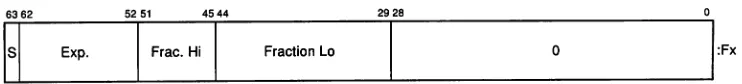
Frac. Hi :A Fraction Lo :A+2An F_floating operand occupies 64 bits in a floating register, left-justified in the 64-bit register, as shown in Figure 2-6.
Figure 2-6: F_floating Register Format
6362 5251 4544 2928 0
Br---
Ex-P.~I
F-rac.-Hir--I
-F-ract-ionL-O~I---o
---....;;.I:FXThe F_floating load instruction reorders bits on the wayinfrom memory, expands the exponent from 8 to 11 bits, and sets the low-order fraction bits to zero. This produces in the register an equivalent G_floating number suitable for either F_floating or G_ floating operations. The mapping from 8-bit memory-format exponents to I1-bit register-format exponents is shown in Table 2-1.
Table 2-1: F_floating Load Exponent Mapping
Memory <14:7> Register <62:52>
1 1111111
1 xxxxxxx
o
xxxxxxx00000000
1 000 1111111
1000xxxxxxx
o
111 xxxxxxxo
000 0000000(xxxxxxx not alII's)
(xxxxxxx not all O's)
This mapping preserves both normal values and exceptional values.
The F_floating store instruction reorders register bits on the way to memory and does no checking of the low-order fraction bits. Register bits <61 :59> and <28:0> are ignored by the store instruction.
AnF_floating datum is specified by its address A, the address of the byte containing bit
o.
The memory form of an F_floating datum is sign magnitude with bit 15 the sign bit, bits <14:7> an excess-128 binary exponent, and bits <6:0> and <31:16> a normalized 24-bit fraction with the redundant most significant fraction bit not represented. Within the fraction, bits of increasing significance are from 16 through 31 and 0 through 6. The 8-bit exponent field encodes the values 0 through 255. An exponent value of 0, together with a sign bit of 0, is taken to indicate that the F_floating datum has a value ofo.
NOTE
Alpha implementations will impose a significant per-formance penalty when accessing F_floating operands that are not naturally aligned. (A naturally aligned F_ floating datum has zero as the low-order two bits of its address.)
2.2.5.2 G_floating
A G_floating datum in memory is 8 contiguous bytes starting on an arbitrary byte boundary. The bits are labeled from right to left, 0 through 63, as shown in Figure 2-7.
Figure 2-7: G_floating Datum
1514 4 3
81
Exp. !Frac.Hi Fraction MidhFraction Midi Fraction Lo
:A :A+2 :A+4 :A+6
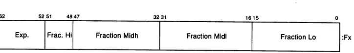
[image:40.514.90.452.334.389.2]A G_floating operand occupies 64 bits in a floating register, arranged as shown in Figure 2-8.
8 Exp. Frac. Hi Fraction Midh Fraction Midi Fraction Lo
Figure 2-8: G_floatlng Format
63 62 52 51 48 47 3231 1615
:Fx
•
A G_floating datum is specified by its address A, the address of the byte containing bit
o.
The form of a G_floating datum is sign magnitude with bit 15 the sign bit, bits <14:4> an excess-1024 binary exponent, and bits <3:0> and <63:16> a normalized 53-bit fraction with the redundant most significant fraction 53-bit not represented. Within the fraction, bits of increasing significance are from 48 through 63, 32 through 47, 16 through 31, and 0 through 3. The II-bit exponent field encodes the values 0 through 2047. Anexponent value of 0, together with a sign bit of 0, is taken to indicate that the G_floating datum has a value ofo.
-1023..1023. An exponent value of 0, together with a sign bit of 1, is taken as a reserved operand. Floating-point instructions processing a reserved operand take a user-visible arithmetic exception. The value of a G_floating datum is in the approximate range 0.56*10**--308..0.9*10**308. The precision of a G_floating datum is approximately one part in 2**52, typically 15 decimal digits.
NOTE
Alpha implementations will impose a significant per-formance penalty when accessing G_floating operands that are not naturally aligned. (A naturally aligned G_ floating datum has zero as the low-order three bits of its address.)
2.2.5.3 D_floating
A D_floating datum in memory is 8 contiguous bytes starting on an arbitrary byte boundary. The bits are labeled from right to left, 0 through 63, as shown in Figure 2-9.
Figure 2-9: D_floating Datum
1514 7 6
sl
Exp. I Frac.Hi Fraction MidhFraction Midi Fraction Lo
:A :A+2 :A+4 :A+6
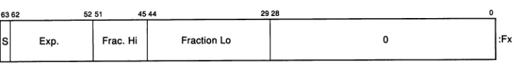
[image:41.513.95.462.428.470.2]A D_floating operand occupies 64 bits in a floating register, arranged as shown in Figure 2-10.
Figure 2-10: D_floating Register Format
6362 5554 4847 3231 1615
S Exp. Frac. Hi Fraction Midh Fraction Midi Fraction Lo :Fx
The reordering of bits required for a D_floating load or store are identical to those required for a G_floating load or store. The G_floating load and store instructions are therefore used for loading or storing D_floating data.
except for 32 additional low significance fraction bits. Within the fraction, bits of increasing significance are from 48 through 63,32 through 47,16 through 31, and 0 through 6. The exponent conventions and approximate range of values is the same for D_floating as F_floating. The precision of a D_floating datum is approximately one part in 2**55, typically 16 decimal digits.
NOTE
D_floating is not a fully supported data type; no D_floating arithmetic operations are provided in the architecture. For backward compatibility, exact D_ floating arithmetic may be provided via software emulation. D_floating "format compatibility" in which binary files of D_floating numbers may be processed, but without the last 3 bits of fraction precision, can be obtained via conversions to G_floating, Garithmetic operations, then conversion back to D_floating.
NOTE
Alpha implementations will impose a significant performance penalty on access to D_floating operands that are not naturally aligned. (Anaturally aligned D_ floating datum has zero as the low-order three bits of its address.)
2.2.6 IEEE Floating-Point Formats
The IEEE standard for binary floating-point arithmetic, ANSIJIEEE 754-1985, defines four floating-point formats in two groups, basic and extended, each having two widths, single and double. The Alpha architecture supports the basic single and double formats, with the basic double format serving as the extended single format. The values representable within a format are specified by using three integer parameters:
1. P-the number of fraction bits
2. Emax-the maximum exponent
3. Emin-the minimum exponent
Within each format, only the following entities are permitted:
1. Numbers of the form (-1)**8 x 2**E x b(O).b(1)b(2)..b(P-1) where:
a. S= 0or 1
b. E = any integer between Emin and Emax, inclusive
c. b(n)
=
0or 12. Two infinities-positive and negative
3. At least one Signaling NaN
4. At least one Quiet NaN
NaN is an acronym for Not-a-Number. A NaN is an IEEE floating-point bit pattern that represents something other than a number. NaNs come in two forms: Signaling NaNs and Quiet NaNs. Signaling NaNs are used to provide values for uninitialized variables and for arithmetic enhancements. Quiet NaNs provide retrospective diagnostic information regarding previous invalid or unavailable data and results. Signaling NaNs signal an invalid operation when they are an operand to an arithmetic instruction, and may generate an arithmetic exception. Quiet NaNs propagate through almost every operation without generating an arithmetic exception.
Arithmetic with the infinities is handled as if the operands were of arbitrarily large magnitude. Negative infinity is less than every finite number; positive infinity is greater than every finite number.
2.2.6~1 S_Floating
An IEEE single-precision, or S_floating, datum occupies 4 contiguous bytes in memory starting on an arbitrary byte boundary. The bits are labeled from right to left, 0 through 31, as shown in Figure 2-11.
Figure 2-11: S_floating Datum
1514 7 6
Fraction La :A S
I
Exp.I
Frac. Hi :A+2 [image:43.513.94.463.429.475.2]An S_floating operand occupies 64 bits in a floating register, left-justified in the 64-bit register, as shown in Figure 2-12.
Figure 2-12: S_floating Register Format
63 62
B
Exp.5251 4544
I
Frac. HiI
Fraction La2928
I
o
o
!:FX
Table 2-2: S_floating Load Exponent Mapping
Memory <30:23> Register <62:52>
1 1111111
1xxxxxxx
o
xxxxxxxo
00000001 111 1111111
1 000 xxxxxxx (xxxxxxx not alII's)
o
111 xxxxxxx (xxxxxxx not all O's)o
000 0000000This mapping preserves both normal values and exceptional values. Note that the mapping for alII's differs from that of F_floating load, since for 8_floating alII's is an exceptional value and for F_floating all 1's is a normal value.
The S_floating store instruction reorders register bits on the way to memory and does no checking of the low-order fraction bits. Register bits <61:59> and <28:0> are ignored by the store instruction. The 8_floating load instruction does no checking of the input.
The 8_floating store instruction does no checking of the data; the preceding operation should have specified an 8_floating result.
An 8_floating datum is specified by its address A, the address of the byte containing bit
o.
The memory form of an S_floating datum is sign magnitude with bit 31 the sign bit, bits <30:23> an excess-127 binary exponent, and bits <22:0> a 23-bit fraction.The value (V) of an 8_floating number is inferred from its constituent sign (8), exponent (E), and fraction (F) fields as follows:
1. If E=255 and F<>O, then V is NaN, regardless of 8.
2. IfE=255 and F=O, then V = {-1)**8 x Infinity.
3. If 0 < E < 255, then V = (-1)**8 x 2**(E-127) x(l.F).
4. If E=O and F<>O, then V = (-1)**8 x 2**{-126) x (O.F).
5. If E=O and F=O, then V = (-1)**8 x 0 (zero).
Floating-point operations on 8_floating numbers may take an arithmetic exception for a variety of reasons, including invalid operations, overflow, underflow, division by zero, and inexact results.
NOTE
Alpha implementations will impose a significant per-formance penalty when accessing S_floating operands that are not naturally aligned. (A naturally aligned 8_ floating datum has zero as the low-order two bits of its address.)
2.2.6.2 T_floating
An IEEE double-precision, or T_floating, datum occupies 8 contiguous bytes in memory starting on an arbitrary byte boundary. The bits are labeled from right to left, 0 through 63, as shown in Figure 2-13.
Figure 2-13: T_floating Datum
1514 4 3 0
Fraction Lo Fraction Midi Fraction Midh
81
Exponent IFrac.Hi:A
:A+2 :A+4 :A+6
A T_floating operand occupies 64 bits in a floating register, arranged as shown in Figure 2-14.
Figure 2-14: T_floating Register Format
6362 5251 4847 3231 1615
8 Exp. Frac. Hi Fraction Midh Fraction Midi Fraction Lo :Fx
The T_floating load instruction performs no bit reordering on input, nor does it perform checking of the input data.
The T_floating store instruction performs no bit reordering on output. This instruction does no checking of the data; the preceding operation should have specified a T_floating result.
A T_floating datum is specified by its address A, the address of the byte containing bit
o.
The form of a T_floating datum is sign magnitude with bit 63 the sign bit, bits <62:52> an excess-l023 binary exponent, and bits <51:0> a 52-bit fraction.The value (V) of a T_floating number is inferred from its constituent sign (8), exponent (E), and fraction (F) fields as follows:
1. IfE=2047 and F<>O, then V is NaN, regardless of 8.
2. If E=2047 and F=O, then V = (-1)**8 x Infinity.
3. If 0 < E < 2047, then V = (-1)**8 x 2**(E-1023) x (I.F).
5. If E=O and F=O, then V = (-1)**8 x 0 (zero).
Floating-point operations on T_floating numbers may take an arithmetic exception for a variety of reasons, including invalid operations, overflow, underflow, division by zero, and inexact results.
NOTE
Alpha implementations will impose a significant per-formance penalty when accessing T_floating operands that are not naturally aligned. (A naturally aligned T_ floating datum has zero as the low-order three bits of its address.)
2.2.7 Longword Integer Format in Floating-Point Unit
A longword integer operand occupies 32 bits in memory, arranged as shown in Figure 2-15.
Figure 2-15: Longword Integer Datum
1514
Figure 2-16: Longword Integer Floating-Register Format
A longword integer operand occupies 64 bits in a floating register, arranged as shown in Figure 2-16.
6362 6159~58 4_5_44 29~2_8 ~o
EtEI
Integer HiI
Integer LaI
0I
:Fx Integer La :A•
:A+2 Integer Hi
81
There is no explicit longword load or store instruction; the S_floating load/store instructions are used to move longword data into or out of the floating registers. The register bits <61 :59> are set by the 8_floating load exponent mapping. They are ignored by S_floating store. They are also ignored in operands of a longword integer operate instruction, and they are set to 000 in the result of a longword operate instruction.
NOTE
Alpha implementations will impose a significant performance penalty when accessing longwords that are not naturally aligned. (A naturally aligned longword datum has zero as the low-order two bits of its address.)
2.2.8 Quadword Integer Format in Floating-Point Unit
A quadword integer operand occupies 64 bits in memory, arranged as shown in Figure 2-17.
Figure 2-17: Quadword Integer Datum
1514
Integer La Integer Midi Integer Midh
sl
Integer Hi:A
:A+2 :A+4 :A+6
A quadword integer operand occupies 64 bits in a floating register, arranged as shown in Figure 2-18.
Figure 2-18: Quadword Integer Floating-Register Format
6362
s Integer Hi
4847
Integer Midh
3231
Integer Midi
1615
Integer La :Fx
There is no explicit quadword load or store instruction; the T_floating load/store instructions are used to move quadword data into or out of the floating registers.
The T_floating load instruction performs no bit reordering on input. The T_floating store instruction performs no bit reordering on output. This instruction does no checking of the data; when used to store quadwords, the preceding operation should have specified a quadword result.
NOTE
2.2.9 DataTypes with No Hardware Support
The following VAX. data types are not directly supported in Alpha hardware.
• Octaword
• H_floating
• D_floating (except load/store and convert to/from G_floating)
• Variable-Length Bit Field
• Character String
• Trailing Numeric String
• Leading Separate Numeric String
• Packed Decimal String
Chapter 3
Instruction Formats (I)
3.1
Alpha Registers
Each Alpha processor has a set of registers that hold the current processor state. If an Alpha system contains multiple Alpha processors, there are multiple per-processor sets of these registers.
3.1.1 Program Counter
The Program Counter (PC) is a special register that addresses the instruction stream. Aseach instruction is decoded, the PC is advanced to the next sequential instruction. This is referred to as theupdated PC. Any instruction that uses the value of the PC
will use the updated PC. The PC includes only bits <63:2> with bits <1 :0> treated as RAZ/IGN. This quantity is a longword-aligned byte address. The PC is an implied operand on conditional branch and subroutine jump instructions. The PC is not accessible as an integer register.
3.1.2 Integer Registers
There are 32 integer registers (RO through R31), each 64 bits wide.
Register R31 is assigned special meaning by the Alpha architecture. When R31 is specified as a register source operand, a zero-valued operand is supplied.
For all cases except the Unconditional Branch and Jump instructions, results of an instruction that specifies R31 as a destination operand are discarded. Also, it is UNPREDICTABLE whether the other destination operands (implicit and explicit) are changed by the instruction. It is implementation dependent to what extent the instruction is actually executed once it has been fetched. It is also UNPREDICTABLE whether exceptions are signaled during the execution of such an instruction. Note, however, that exceptions associated with the instruction fetch of such an instruction are always signaled.
There are some interesting cases involving R31 as a destination:
• STx_C R31,disp(Rb)
Although this might seem like a good way to zero out a shared location and reset the lock_flag, this instruction causes the lock_flag and virtual location {Rbv +
SEXT(disp)} to become UNPREDICTABLE.
• LDx_L R31,disp(Rb)
This instruction produces no useful result since it causes both lock_flag and locked_physical_address to become UNPREDICTABLE.
Unconditional Branch (BR and BSR) and Jump (JMP, JSR, RET, and JSR_ COROUTINE) instructions, when R31 is specified as the Ra operand, execute normally and update the PC with the target virtual address. Of course, no PC value can be saved in R31.
3.1.3 Floating-Point Registers
There are 32 floating-point registers (FO through F31), each 64 bits wide.
When F31 is specified as a register source operand, a true zero-valued operand is supplied. See Section 4.7.2 for a definition of true zero.
Results of an instruction that specifies F31 as a destination operand are discarded and it is UNPREDICTABLE whether the other destination operands (implicit and explicit) are changed by the instruction. In this case, it is implementation-dependent to what extent the instruction is actually executed once it has been fetched. It is also UNPREDICTABLE whether exceptions are signaled during the execution of such an instruction. Note, however, that exceptions associated with the instruction fetch of such an instruction are always signaled.
A floating-point instruction that operates on single-precision data reads all bits <63:0> of the source floating-point register. A floating-point instruction that produces a single-precision result writes all bits <63:0> of the destination floating-point register.
3.1.4 Lock Registers
There are two per-processor registers associated with the LDx_L and STx_C instructions, the lock_flag and the locked_physical_address register. The use of these registers is described in Section 4.2.
3.1.5 Optional Registers
Some Alpha implementations may include optional memory prefetch or VAX compatibility processor registers.
3.1.5.1 Memory Prefetch Registers
If the prefetch instructions FETCH and FETCH_M are implemented, an implementation will include two sets of state prefetch registers used by those instructions. The use of these registers is described in Section 4.11. These registers are not directly accessible by software and are listed for completeness.
3.1.5.2 VAX Compatibility Register
The VAX compatibility instructions RC and RS include the intr_flag register, as described in Section 4.12.