DC Motor Angular Position Control using PID
Controller with Friction Compensation
Myo Maung Maung*, Maung Maung Latt**, Chaw Myat Nwe**
*
Department of Electronic Engineering, Mandalay Technological University, Republic of the Union of MYANMAR
**
Technological University, Taungoo, Republic of the Union of MYANMAR
***
Department of Electronic Engineering, Mandalay Technological University, Republic of the Union of MYANMAR
DOI: 10.29322/IJSRP.8.11.2018.p8321 http://dx.doi.org/10.29322/IJSRP.8.11.2018.p8321
Abstract- This paper finds to get the precision of angular position control for DC geared motor using PID controller. The Arduino microcontroller board is mainly used to control the 12V brushed Namiki DC motor. L298N dual H-bridge motor driver is applied to execute the pulse width modulation (PWM) signal and to drive the direction control. The implementation code is considered to generate the PWM output using PID (proportional, integral and derivative) tuning algorithms. According to the PID tuning method, errors are not only solved but also taken to its minimal value with very low amount of error oscillations. In this work, step input, sine input and potentiometer input are tested to analyze the system performance. The results were clearly seen, the controller output response curve is very well-matched to approach the desired position. But, it has a few errors when the orientation of changes angle because they are not fast to reach the desired position. Therefore, friction compensation according to the velocity effect is considered. After compensating the friction effect, the PID output results were very precise to get the desired angle. This stability performance using PID controller can be applied for robotic arm position control system and other industrial applications.
Index Terms- DC-Gear motor,L298 Motor Driver, PID, PWM control
I. INTRODUCTION
owadays,the DC motors are used in various applications such as defense, industries, robotics because of their simplicity, ease of application, reliability and cost effective. Generally in a DC Motor, speed control can be achieved by varying the terminal voltage but position control of the shaft cannot be achieved. The position control of a DC motor is crucial in applications for precision control system. The purpose of a motor position controller is to take a signal representing the required angle and to drive a motor at that position. Microcontrollers can provide easy control of a DC motor. A microcontroller-based position control system consists of an electronic component and a microcontroller. There are many applications of DC motor drives that use power electronics to control the voltage and consequently the speed or position of the
motor [1].
In this paper, 12V Namiki DC motor with a metal gearbox is used which has an integrated quadrature encoder. The encoder’s read value is corresponding to the motor pulse counts per revolution of gearbox’s output shaft. Geared DC motors on the other hand, can provide high torque. The torque generated at the output shaft of a DC motor can be scaled up or scaled down by using a gear train [2]. Therefore, this system can get the high torque position and low speed by using geared DC motor to provide a feedback loop. Bi-directional motor control can be done using an L298 H-Bridge module with pulse-width modulation (PWM) from an Arduino microcontroller. The PWM control signal is calculated by proportional-integral-derivative (PID) tuning algorithms. PID controller is a generic control loop feedback mechanism widely used in industrial control systems. A PID controller attempts to correct the error between a measured process variable and a desired set point by calculating and then outputting a corrective action that can adjust the process accordingly. So by integrating the PID controller to the DC motor were able to correct the error made by the DC motor and control the speed or the position of the motor to the desired point or speed.
This paper obviously sees the real time DC motor position control for the various input value of position. Step function, sine function and variable resistor are used as an input signal to test the DC motor position. Besides, friction compensation according to the velocity dependence is considered to eliminate the friction effect. By applying the Coulomb’s friction force on the driving velocity, the performance of the output results is better to get the desired position of DC motor.
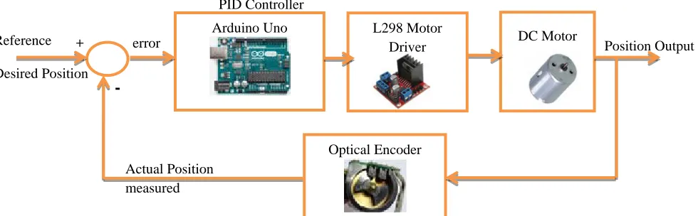
II. SYSTEM BLOCK DESCRIPTION
The block diagram for overall system description is shown in Fig.1. In this block, three main hardware components are implemented for this research. Arduino Uno microcontroller is to control the position of DC motor by controlling the input voltage
Figure 1: Block Diagram for DC Motor Position Control to the motor. PID tuning algorithms is implemented in
microcontroller to execute the PWM signal for DC motor drive. A 12V Namiki DC gear-motor is a powerful motor to drive the position control system. It comes with the photoelectric encoder output, planetary gear reducer and 80:1 gear ratio, which provide 120 rpm with 12VDC rated voltage. L298 dual H-Bridge motor driver which is allows controlling the direction and position of DC motor.
III. HARDWARE DEVICES
A. Arduino Uno Microcontroller
[image:2.612.329.543.376.531.2]Arduino Uno is a microcontroller board based on the ATmega328P shown in Fig. 2. It has 14 digital input/output pins (of which 6 can be used as PWM outputs), 6 analog inputs, a 16 MHz quartz crystal, a USB connection, a power jack, an ICSP header and a reset button. It contains everything needed to support the microcontroller; simply connect it to a computer with a USB cable or power it with a AC-to-DC adapter or battery to get started [3]. In this paper, the Arduino microcontroller is very well-suited to drive the PWM signal for DC motor for the improvement of the output response for the DC motor position control system.
Figure 2: Arduino Uno Microcontroller
B. L298N Dual H-Bridge Controller
The L298N H-bridge IC shows in Fig. 3 that can allow to control the speed and direction of two DC motors. This module can be used with motors that have a voltage of between 5 and 35V DC with a peak current up to 2A. The module has two screw terminal blocks for the motor A and B, and another screw terminal block for the Ground pin, the VCC for motor and a 5V
pin which can either be an input or output. Pin assignments for L298N dual H-Bridge Module is shown in table 1. The digital pin assign from HIGH to LOW or LOW to HIGH is used IN1and IN2 on the L298N board to control the direction. And the controller output PWM signal is send to ENA or ENB to control the position. The forward and reverse speed or position controlling for the motor has done by using PWM signal [4]. Then using the analogWrite() function and send the PWM signal to the Enable pin of the L298N board, which actually drives the motor.
[image:2.612.99.238.519.620.2]Table.1 Pins assignment for L298
Figure 3: L298N dual H-Bridge Controller Module Out 1: Motor A lead out
Out 2: Motor A lead out Out 3: Motor B lead out Out 4: Motor B lead out GND: Ground
5V : 5V input
ENA: Enables PWM signal for Motor A IN1: Enable Motor A
IN2: Enable Motor A IN3: Enable Motor B IN4: Enable Motor B
ENB: Enables PWM signal for Motor B Actual Position
measured Reference
Desired Position
error Position Output
Arduino Uno
DC Motor
Optical Encoder
+
[image:2.612.327.563.532.709.2]
C. DC Geared Motor
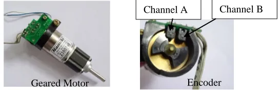
[image:3.612.345.526.130.238.2]The 12V Namiki DC gear-motor shown in Fig. 4 is a powerful motor to drive the position control system. It comes with the photoelectric encoder output and planetary gear ratio reduced by 80:1 gear. It can provide 120 rpm with the rated voltage of 12VDC [5]. To read the count values from the encoder, the user would check the condition of channel A and B rotation applying by experiment. For the rotor shaft count per revolution values, it is very important to multiply the gear ratio by count values. The specification of the motor is shown in Table 2.
[image:3.612.37.310.181.269.2]Figure 4: Namiki DC Geared Motor with Encoder Table. 2 Namiki motor features
Brand Namiki Coreless Motor
Model 22CL-3501PG
Operating Voltage 12 V DC
Rated Power 15 W
Stall torque 16.5 kg.cm Continuous torque 5 kg.cm
Diameter 22mm
Shaft length 19mm
Length 65mm(excluding encoder,
gear box and output shaft Stall current 1.8A
Reduction ratio 80:1 Output speed 120 rpm
[image:3.612.59.278.308.451.2]Weight 140g
[image:3.612.358.540.330.463.2]Fig. 5 shows about the encoder circuit for Namiki 12V DC motor. It is needed to connect two 10k Ohms to channel A and channel B supplied by 5V. One of the encoder pins is connected with 120 Ohms resistor and another pin ground.
Figure 5: Encoder Circuit for DC Geared Motor
D. Reading the Encoder Pulse
In this research work, the encoder comes with the photoelectric encoder output (channel A and channel B). It is used to sense the rotation of a magnetic disk on a rear protrusion of the motor shaft forward or backward direction according to the pulse count per revolution. From Fig. 6, it is the clockwise direction from channel A leading to channel B because the A interrupt seeing
attached to B whenever it changes state LOW to HIGH or HIGH to LOW condition. The another direction is counterclockwise caused by channel B leading to channel A because the B interrupt seeing attached to A whenever it changes state LOW to HIGH or HIGH to LOW condition[6].
Figure 6: Encoder Channel Description
The encoder read values for channel A and channel B can be seen in serial monitor. Fig. 7 shows the values of count per revolution of the rotor shaft according to the multiplication of gear ratio 80 and encoder count values 8. Besides, the count values for forward and backward direction of the rotor shaft can be seen in the serial monitor.
Figure 7: Encoder Read Values for DC Geared Motor
E. Calculating the Angular Position
The encoder from the gear-motor provides a resolution of 8 counts per revolution and exact gear ratio is 80:1 metal gearbox. Therefore, it can get the counts per revolution (CPR) to the angular position as the following calculation:
CPR = 8×80 CPR
Count/degree = 640counts/rev ×1rev/360 deg Let X = 640 counts/ 360 deg
Therefore 1/X = 360 deg/ 640counts For attachInterrupt X2
angular position = (1/X) × 2×counts = (720/640) deg
The instruction code was implemented in the program by using the above equation to get the angular position of the DC motor.
IV. PIDCONTROL
A. PID Tuning Algorithms
A proportional–integral–derivative controller (PID controller) is a generic control loop feedback mechanism widely used in Channel A Channel B
Encoder Geared Motor
Turn Right
Turn Left A B
[image:3.612.95.241.515.620.2]industrial control systems. A PID controller calculates an "error" value as the difference between a measured process variable and a desired set point. The controller attempts to minimize the error by adjusting the process control inputs [7]. Fig.8 mentions implementation program flow chart for this setup.
Figure 8: Flowchart for System Description
[image:4.612.336.549.472.672.2](1)
Fig. 9 shows the PID controller design for this control system. PID equation is calculated to get the control signal for DC motor. From eq (1), e(t) is position error value difference between set angle and output measured angle(actual angle), u(t) is PWM signal for DC motor and y(t) is the actual angle. Kp, Ki and Kd were respectively with the values of proportion, integral, and the differential coefficient.
Figure 9: Closed Loop Position Control of the DC Motor using PID Controller
The programming code for PWM signal execution is calculated by the following procedure. The instruction code is implemented by the Arduino microcontroller to execute the control signal.
error = output - input; Integral = xT * error + prv_ui; Diff = (error - prv_error) / xT
PWM = kp * error + ki * Integral + kd * Diff; Usignal = abs (PWM);
From above code, the proportional gain (Kp) examines the magnitude of the error and it responds proportionally. Although it has a large error, the magnitude of the motor position will receive a large response. The integral gain (Ki) efforts to reduce the steady state error. And the derivative gain (Kd) attempts to look at the rate of change of the error signal. Derivative control will decrease the overshoot to become a greater system response curve of the motor position to a rapid rate of change. Finally, the controller is calculated the PWM signal depends on the signal variation of DC motor by using PID gain values to improve the system performance.
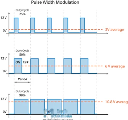
B. Pulse Width Modulation
PWM, or pulse width modulation is a technique which allows adjusting the average value of the voltage that’s going to the electronic device by turning on and off the power at a fast rate. The average voltage depends on the duty cycle, or the amount of time the signal is ON versus the amount of time the signal is OFF in a single period of time. It is depending on the size of the motor, the user can simply connect an Arduino PWM output to the base of transistor or the gate of a MOSFET and then control the speed or position of the motor by controlling the PWM output [8]. PWM and duty cycle relation diagram is shown in Fig. 10.
Figure 10: PWM and Duty Cycle Diagram
In this paper, the value of PWM signal is from 0 to 255 or that’s 0 to 100% duty cycle of the PWM signal. The duty cycle diagram is as shown in Fig.11. The PWM value is executed by
𝒖(𝒕) =𝑲𝒑𝒆(𝒕) +𝑲𝒊� 𝒆(𝝉)𝒅𝝉+𝑲𝒅𝒅𝒆𝒅𝒕(𝒕) 𝒕
𝟎
Start
Initialize variables, timer and PWM
Get set point and direction of DC motor
Read actual position
Calculate error (e= Set- Actual)
Apply PWM duty cycle Calculate PID
control signal
Drive the motor
Display set point and actual position
End
F
eed
b
ack
D I P
Motor
Sensor error
Control signal
Actual angle Set angle
Feedback +
+ + + -
y(t) u(t)
[image:4.612.32.297.619.710.2]PID controller to reduce the error difference between the desired angle and the actual angle.
Figure 11: Duty Cycle Diagram
The duty cycle of PWM signal is calculated by the following equation.
Period = 1/Frequency (2) Period= Ton+Toff (3)
Duty Cycle= Ton/ (Ton+Toff) * 100 (percentage) (4)
[image:5.612.333.545.168.348.2]V. EXPERIMENTAL TEXT AND RESULTS Experimental setup for the DC motor angular position control is shown in Fig. 12. All of the measurement values can be seen in serial monitor or serial plotter. Getting from the serial values, the output result curves are plotted by using MATLAB to be seen clearly.
Figure 12: Experimental Setup for DC motor Position Control
[image:5.612.55.280.339.495.2]A. Testing Results using PID
Figure 13: Output Response for Sine Input
Fig. 13 shows the test result of the DC motor position controlled system. It can be seen the satisfied results achieved for free wheel (no load) condition. For this experiment, the input signal is used the magnitude of 90 degree for ‘Sine’ function.
After testing several experiments for tuning the PID controller, the best result for Kp, Kd and Ki values were achieved. In this condition, the values of the best result are Kp=1.51, Kd=0.05 and Ki=0.009. But, the performance still occurs a little delay time between the desired and actual positions.
Figure 14: Output Response for Step Input
In Fig. 14, the desired ‘Step’ input signal is set about 90 degree for the DC motor position control. According to the response, the output signal is very fast within the settling time of 0.5 second and steady state error is closely to zero. However it has a little overshoot and oscillation to reach the desired position for the best results. To reduce this situation, the effect of friction should be considered according to the low velocity condition. In this research work, the friction compensation due to the low velocity was emphasized.
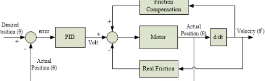
B. Testing Results using PID and Friction Compensation
[image:5.612.55.271.550.718.2]For the control engineers, friction is also very important for various fields such as design of drive systems, high-precision servo mechanisms, robots, pneumatic and hydraulic systems. Friction is highly nonlinear and may result in steady state errors, limit cycles, and poor performance. It is therefore important for control engineers to understand friction phenomena and to know how to deal with them. The friction force is lower for decreasing velocities than for increasing velocities. The effects of friction on a closed loop, design control laws decrease the effects of friction. The friction compensation block model for DC motor position control system is shown in Fig. 15.
[image:5.612.316.576.628.708.2]The goal of this paper is to apply the Coulomb friction compensation for reducing the effects of friction. Coulomb friction is independent of velocity and is always present. This friction component is only dependent on the direction of motion, in such way that it is in the direction opposite to the velocity. The magnitude of Coulomb friction depends on the properties of the surfaces in contact and the normal force [9].
[image:6.612.319.557.157.333.2]Fc = µ FN (5)
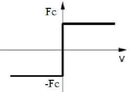
Figure 16: Representation of Coulomb Friction
The description of friction (Fc) is Coulomb friction
proportional to the normal load. Fig. 16 describes the sign function behavior of equation (5). The Coulomb friction model does not require the friction force for zero velocity. It may be zero or it can take on any value in the interval between −Fc and
[image:6.612.104.236.163.257.2]Fc, depending on how the sign function is defined.
Figure 17: Output Response for Sine Input applying Friction Compensator
Figure 18: Output Response for Step Input applying Friction Compensator
After compensating the Coulomb friction effect, the PID gain tuning parameters were changed a little and Fc values are added
in the implementation procedure.
Fig. 17 and Fig. 18 points out a good result in which Kp=0.51, Ki=0.007, Kd=0.05. Fc=2.25 for velocity greater than zero, Fc= -1.25 for velocity less than zero and Fc=0 for zero velocity. Moreover, these optimal values covers for potentiometer input too. This condition can be seen in Fig. 19.
[image:6.612.313.574.360.524.2][image:6.612.55.270.365.716.2]
Figure 19: Output Response for Potentiometer Input
Figure 20: Varies the Output Position Response for DC Motor Fig 20 shows variety of responses in which wide ranges of inputs are applied up to 270 degree changes. The blue line response curve is variety of desired input angle and the red line response curve is the actual output angle for Namiki DC motor. The responses give high accuracy in a very short of milli-second time.
VI. CONCLUSION
[image:6.612.65.264.365.519.2] [image:6.612.60.267.545.713.2]criteria of the control system. Therefore, the experimental results are very optimal to get the desired angular position of DC motor.
For the further extension work, this research can be implemented for the cases of the robot arm model, load consideration and robust controller selection to get the best performance for the stability system.
ACKNOWLEDGMENT
The author would like to thank to all the teachers from Department of Electronic Engineering, Mandalay Technological University (MTU) for their suggestions and encouragement. In particular, I would like to thank my family and friends who have helped me during this research.And also, thanks for Dr. Tin Tin Hla, head of the department, MTU.
REFERENCES
[1] K. Sailan and K.D. Kuhnert, “DC Motor Angular Position Control using PID Controller for the purpose of controlling the Hydraulic Pump”, International Conference on Control, Engineering and Information, Vol. 1, No. 2, pp. 22,26, 2013.
[2] H. Paul and S. Lasrado, “Precise Control of Angular Position of Geared DC Motors for Low Cost Applications”, International Journal of Innovative Research in Science,Engineering and Technology, Vol. 5, Special Issue 9, May 2016.
[3] https://store.arduino.cc/usa/arduino-uno-rev3
[4] [Online].Available: http://www.instructables.com/id/Control-DC-and-stepper-motors-with-L298N-Dual-Motor/
[5] https://www.dfrobot.com/product-1460.html
[6] https://www.google.com.mm/search?q=encoder+pulse&dcr=0&source=lnm s&tbm=isch&sa=X&ved=0ahUKEwi0uJ2GjsrYAhUDlJQKHQxfBAoQ_A UICigB&biw=1366&bih=628
[7] Detchrat, et. al. , "IMC-Based PID Controllers Design for Two-Mass System", IMECS 2012 Volume - II, Hong Kong.
[8] https://howtomechatronics.com/tutorials/arduino/arduino-dc-motor-control-tutorial-l298n-pwm-h-bridge/
[9] H. Olsson, K. J. Åström, C. Canudas de Wit, M. Gäfvert, and P. Lischinsky, “Friction models and friction compensation”, European journal of control, No. 4, pp. 176-195, December 1998.
AUTHORS
First Author – Myo Maung Maung (M.E, Electronics), Lecturer, Department of Electronic Engineering, Mandalay Technological University, Republic of the Union of Myanmar, [email protected].
Second Author – Maung Maung Latt, Ph.D (Electronics), Rector, Technological University (Taungoo), [email protected].