International Journal of Emerging Technology and Advanced Engineering
Website: www.ijetae.com (ISSN 2250-2459,ISO 9001:2008 Certified Journal, Volume 4, Issue 6, June 2014)
943
Performance comparison of Haze Detection by Multiscale
fusion and Universal Dehazing with Directed Filter Method
Dinesh Kumar Patel, Amit Kumar Rajput
M.Tech.(Digital Communication), RITS, Bhopal, Madhya Pradesh, India. Assistant Professor (E&C) RITS, Bhopal, Madhya Pradesh, India.
Abstract—Haze is an atmospheric singularity that significantly degrades the visibility of outdoor scenes. This is mainly due to the atmosphere particles that absorb and scatter the light. We generate the spread map by estimating the atmospheric light except a continuous region which has no edge information. The method performs a per-pixel manipulation, which is straightforward to implement and then apply the Directed filter to improve the image quality. The experimental results demonstrate that the method yields results comparative to and even better than the more complex state-of-the-art techniques, having the advantage of being appropriate for real-time applications.
Keywords— Haze detection, Dehazing, Directed filter, universal dehazing and single image dehazing.
I. INTRODUCTION
Haze is an annoying factor when it shows up in the image since it causes poor visibility. This is the major problem of some applications in the field of computer vision, such as surveillance, object recognition, etc. In order to obtain the clear images, haze removal is inevitable. Fog, mist and some other particles that degrade the scene image are the results of atmospheric absorption and light scattering. The radiance achieved to camera along the sightline is decreased due to atmospheric light and it is replaced by previously scattered light, which is called the airlight. This degradation will cause the image to lose contrast and color correctness. Furthermore, the airlight which affect the image depends on the depth of the scene. This knowledge is commonly used for dehazing problems. We also adopt this clue to solve the haze removal problem. Image haze removal has gotten a growing interest recently. More and more methods are introduced in the past three years. Nevertheless, dehazing is a challenging topic since the haze is dependent on the unknown depth information. Often, the images of outdoor scenes are degraded by bad weather conditions. In such cases, atmospheric phenomena like haze and fog degrade significantly the visibility of the captured scene. Since the aerosol is misted by additional particles, the reflected light is scattered and as a result, distant objects and parts of the scene are less visible, which is characterized by reduced contrast and faded colors.
International Journal of Emerging Technology and Advanced Engineering
Website: www.ijetae.com (ISSN 2250-2459,ISO 9001:2008 Certified Journal, Volume 4, Issue 6, June 2014)
944
II. MULTI-SCALE FUSION
In the fusion process, the inputs are weighted by specific computed maps in order to conserve the most significant detected features. Each pixel x of the output F is computed by summing the inputs weighted by corresponding normalized weight maps :
(1) Where symbolizes the input (k is the index of the inputs) that is weighted by the normalized weight maps . The normalization of the weights ensures that the intensity scale of the result is maintained in relatively the same scale as the inputs (since the sum of each pixel equals 1, ). The naive solution (please refer to figure 5) that directly implements this equation, introduces strong halos artifacts, mostly in the locations characterized by strong transitions of the weight maps. To prevent such degradation problems, we have opted for the adapted solution that employs a classical multi-scale pyramidal refinement strategy [17]. We also tested several more recent edge preserving techniques (e.g. WLS [18]) but we did not obtain significant improvement. However, recent advanced methods need, in general, to tweak their parameters, as well as being more computationally intensive. In our case, each input , is decomposed into a pyramid by applying Laplacian operator at different scales. Similarly, for each normalized weight map , a Gaussian pyramid is computed. Considering that both the Gaussian and Laplacian pyramids have the same number of levels, the mixing between the Laplacian inputs and Gaussian normalized weights is performed at each level independently, yielding the fused pyramid
(2) Where l represents the number of the pyramid levels (default value of the number of levels is l=5) and is the Laplacian version of the input I while represents the Gaussian version of the normalized weight map of the . This step is performed successively for each pyramid layer, in a bottom-up manner. The final haze-free image J is obtained by summing the contribution of the resulting inputs (levels of pyramid)
(3) Where is the upsampling operator with factor . As a default characteristic, in our implementation the contribution of all the three weight maps is equally distributed.
III. HAZE DETECTION BY UNIVERSAL DEHAZING METHOD
Human eyes are more sensitive to brightness than color. Therefore we use the atmospheric light estimation and produce a transmission map in the color channels. The atmospheric light is estimated from the most opaque pixel. The existing algorithm picks up the top 0.1% brightest pixels in the dark channel prior. Sine an image does not have information on the edge of the sky or a wall in the area, the mis-estimated value of the atmospheric light results in failure of the defogging (dehazing) algorithm. Therefore we use the edge information to represent the neighboring pixel’s relative depth information. With this relative depth information we can construct the corresponding atmospheric light to restrain the edge halation. We generate the transmission map by estimating the atmospheric light except a continuous region which has no edge information. And the transmission map is given as,
(4)
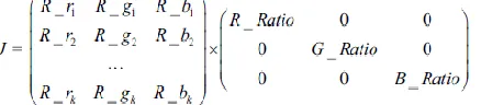
(5) where 0 t restricts the transmission t (x) to a lower bound 0 t ,which means that a small amount of fog are preserved in very dense fog regions. In the experiment we used 0 t _ 0.1 .Color distortion problem may occur in the compensation process. To solve this problem, the image restored by color correction using statistical RGB channel feature extraction of image. We calculate the RGB channel ratio between foggy and defogged images for color correction with weighted image. The RGB channel ratio is defined as,
Where R represents the defogged image an O the foggy image. As a result, we can obtain the color-corrected image using color matching of RGB channels of restored image, such as
[image:2.612.327.546.618.666.2]International Journal of Emerging Technology and Advanced Engineering
Website: www.ijetae.com (ISSN 2250-2459,ISO 9001:2008 Certified Journal, Volume 4, Issue 6, June 2014)
945
A.Directed filter Image modelling for Haze
Extraction
The entire document should be in Times New Roman or Times font. The observed brightness of a capture image in the presence of haze can be modelled based on the atmospheric optics [6, 7,11] via
(6)
where, I(x) is the observed haze image, J(x) is scene irradiance(the clear haze-free image), A is the airlight that represents the ambient light in the atmosphere. t(x)ϵ[0, 1] is the transmission of the light reflected by the object, which indicates the depth information of the scene objects directly. J(x)t(x)on the right hand side is called direct attenuation, which describes the scene radiance and its decay in the medium. The second term A(1-t(x))is the atmospheric veil (atmospheric scattering light), which causes fuzzy, color shift, and distortion in the scene. The goal of haze removal is to recover J(x), A and t (x) from I(x).
i. Extract the Transmission
The core of haze removal for an image is to estimate the airlight and transmission map. Assuming the airlight is already known, to recover the haze free image, the transmission map should be extracted first. He et al. [8] found that the minimum intensity in the non-sky patches on haze free outdoor images should have a very low value, which is called dark channel prior. Formally, for an image J, the dark channel value of a pixel x is defined as:
(x) =
where, is a color channel of J ; Ω(x) is a patch around x. By assuming the transmission in a local patch is constant and taking the min operation to both the patch and three color channels, the haze imaging model in (4) can be transformed as:
= (x)
+ (1- (x)) (7) where, (x) is the patch transmission. Since A is always positive and the dark channel value of a haze-free image J tends to be zero according to the dark channel prior, we have
→ 0
Then the transmission can be exacted simply by:
(x) = (8)
Although the dark channel prior is not a good prior for the sky regions, fortunately, both sky regions and non-sky regions can be well handled by (8) since the sky is infinitely distant and its transmission is indeed close to zero. In practice, the atmosphere is not absolutely free of
any particle even in clear weather. Therefore, a constant parameter ω(0<ω≤1) is introduced into(8) to keep a small amount of haze for the distant objects:
(x) = 1- ω (9)
The estimated transmission maps using (9) is reasonable. The main problems are some halos and block artifacts. This is because the transmission is not always constant in a patch. Several techniques were proposed to refine the transmission map, such as soft matting and directed joint bilateral filter. These techniques were applied on the transmission maps of the original foggy images and usually several operations should be used to achieve a good result, which could be computational intensive. For image haze removal, the time complexity is a critical problem that needs to be addressed. High time complexity of dehazing may make the algorithm impracticable.
ii. Refine the Transmission
To improve the efficiency, in the present implementation, the transmission map is obtained form a down-sampled minimum channel image. Then, it is refined and up-sampled by using directed filter, which can be explicitly expressed by [11]:
( ) (10)
( ) = (11)
Where, is the guidance image; and are the mean and variance of in ; |w| is the number of pixels in . is a regularization parameter. The refined operation on a down-sampled minimum channel image leads to a low time complexity and helps to reduce halos and block artifacts. Joint upsampling using directed filter is applied to obtain the full transmission map. The directed filter is reported to be a fast and non-approximate linear-time algorithm, which can perform as an edge preserving, smoothing operator like the bilateral filter.
IV. WORK FLOW AND ALGORITHM
International Journal of Emerging Technology and Advanced Engineering
Website: www.ijetae.com (ISSN 2250-2459,ISO 9001:2008 Certified Journal, Volume 4, Issue 6, June 2014)
946
Figure1 Flow chart and Algorithm for Haze Removal
V. PERFORMANCE PARAMETERS
For a good algorithm, values of these evaluation metrics should be high. Modelling the Markov pdf parametrically involves the data driven optimal estimation of the parameters associated with the potential functions Vc. The model parameters must be estimated for each data set as part of the image processing algorithm. In our algorithms, the noise variance in (13) and the parameter a in the coefficient MRF pdf in (14) are unknown. Thus, we need to estimate these parameters in our algorithms. Because we assume that the noise in the fusion model is a Gaussian noise, it is straightforward to estimate the noise variance by the maximum likelihood (ML) criterion. It is given by
(13) The direct ML estimation of the parameters associated with the pdf of H is known to be a difficult problem [32]. The ML estimate of a is
(14)
The potential function can be simply computed. However, the normalization term ZH involves a summation over all possible configurations of H, which is practically impossible due to the large computation time. Note that, for two source images with size 300 *300, H has a total of 490000 possible configurations. An alternative method for approximation to ML estimation is maximum pseudo likelihood (MPL) estimation, which was proposed by Besag [15]. The MPL estimation method is a suboptimal method, which is given by
= . (15)
The differences among the fused results are usually difficult to be measured only based on observation, particularly when the fused images are multiband. Objective and quantitative analysis can benefit to a comprehensive evaluation.
1) SNR: The SNR in decibels, as shown in (19), is a direct index to compare the fused image to the reference one [16].For multiband images, it can be calculated band-by-band and also globally averaged SNR
(16)
2) Universal Image Quality Index (UIQI): A UIQI [14] has been widely used for image similarity evaluation and was also applied to validate fusion techniques [13]. UIQI of two images (A and B) is defined as
(17)
This quality index models any distortion as a combination of three different factors: loss of correlation, luminance distortion, and contrast distortion. The dynamic range of Q is [−1,1], and the best value 1 is obtained if A = B. When applying this index to a multiband image, it is applied band-by-band and averaged over all bands. [16]. 3).Performance of the image compression coding, it is necessary to define a measurement that can estimate the difference between the original image and the decoded image. Two common used measurements are the Mean Square Error (MSE) and the Peak Signal to Noise Ratio (PSNR), which are defined in (2.3) and (2.4), respectively. f(x,y) is the pixel value of the original image, and f’(x,y)is the pixel value of the decoded image. Most image compression systems are designed to minimize the MSE and maximize the PSNR.
(18)
(19)
VI. RESULT ANALYSIS
T he algorithm proposed here will remove haze from an image surface without prior knowledge of the haze location upon that surface. The proposed method is based on determining the illumination profile of the image surface. This profile is then used to remove the haze. It is implemented using MATLAB 7.9.0 (R2009b) on i-5 processor with 4-GB RAM.
Input image
Image segmentation
Air light Estimation
Transmission map Estimation by universal dehazing method
Recovering the Scene Radiance by Directed filter
International Journal of Emerging Technology and Advanced Engineering
Website: www.ijetae.com (ISSN 2250-2459,ISO 9001:2008 Certified Journal, Volume 4, Issue 6, June 2014)
947
The simulations have been tested on aerial images in figure 2 and 3; Figure 2 shows the Original Image of House image of haze Removed Image.
Figure: 2 (a) Original Image of house, (b) Dehazed Image by using Multi scale Fusion (c) Dehazed Image by using Universal Dehazing (d) Dehazed Image After Directed filter.
TABLE 1
COMPARISON PARAMETERS FOR IMAGE OF HOUSE
Method Variance Mean SNR UIQI Multiscale
Fusion 0.1039 0.5315 6.2288 2.7719 Universal
Dehazing 0.1344 0.4342 6.0875 2.5927
VII. CONCLUSION AND FUTURE SCOPE
In this paper, a fast and effective method for real-time image and video dehazing is proposed. Using a newly presented image prior - dark channel prior, haze removal for a single image without using any extra information is formulated as a particular filtering problem and an improved filtering scheme is proposed based on directed filter. In the presented algorithm, the airlight and the down-sampled transmission can be estimated and extracted easily. Then using a directed filter, the transmission can be further refined and up-sampled. Results demonstrate the presented method abilities to remove the haze layer and achieve real-time performances. It is believed that many applications, such as outdoor surveillance systems, intelligent vehicle systems, remote sensing systems, graphics editors, etc, could benefit from the proposed method
.
Figure: 3 (a) Original Image of forest, (b) Dehazed Image by using Multi scale Fusion (c) Dehazed Image by using Universal Dehazing (d) Dehazed Image After Directed filter.
TABLE 2
COMPARISON PARAMETERS FOR FOREST IMAGE
Method Variance Mean SNR UIQI Multiscale
Fusion 0.0337 0.3913 6.2345 4.8957 Universal
Dehazing 0.0407 0.3463 8.0638 6.5275
REFERENCES
[1] P. Chavez, 1988 An improved dark-object subtraction technique for atmospheric scattering correction of multispectral data, Remote Sens. Environ., vol. 24, no. 3, pp. 459–479.
[2] G. D. Moro and L. Halounova, 2006 Haze removal and data calibration for high-resolution satellite data, Int. J. Remote Sens., pp. 2187–2205.
[3] S. Narasimhan and S. Nayar, Jun. 2003 Contrast restoration of weather degraded images, IEEE Trans. Pattern Anal. Mach. Intell., vol. 25, no. 6, pp. 713–724,.
[4] J. Kopf, B. Neubert, B. Chen, M. Cohen, D. Cohen-Or, O. Deussen, M. Uyttendaele, and D. Lischinski, 2008 Deep photo: Model-based photograph enhancement and viewing, ACM Trans. Graph., vol. 27, no. 5, p. 116,.
[5] T. Treibitz and Y. Y. Schechner, Jun. 2009 Polarization: Beneficial for visibility enhancement? in Proc. IEEE Conf. Comput. Vis. Pattern Recognit., pp. 525–532.
[6] R. Fattal, 2008 Single image dehazing, ACM Trans. Graph., SIGGRAPH, vol. 27, no. 3, p. 72.
[7] R. T. Tan, Jun. 2008 Visibility in bad weather from a single image, in Proc. IEEE Conf. Comput. Vis. Pattern Recognit., pp. 1–8. [8] K. He, J. Sun, and X. Tang, Jun. 2009 Single image haze removal
using dark channel prior, in Proc. IEEE Conf. Comput. Vis. Pattern Recognit., , pp. 1956–1963.
[9] J.-P. Tarel and N. Hautiere, Sep.–Oct. 2009 Fast visibility restoration from a single color or gray level image, in Proc. IEEE Int. Conf. Comput. Vis., , pp. 2201–2208.
(a)
(b)
(c)
(d)
Dehazed Image after using Guided Filter
50 100 150 200 250
50
100
150 Dehazed Image after using Blind Dehazing method
50 100 150 200 250
50
100
150
Dehazed image by multiscale fusion
50 100 150 200 250
50
100
150 Original hazy image
50 100 150 200 250
50
100
150
(a)
(b)
[image:5.612.344.541.137.317.2] [image:5.612.58.259.158.395.2] [image:5.612.57.280.442.510.2]International Journal of Emerging Technology and Advanced Engineering
Website: www.ijetae.com (ISSN 2250-2459,ISO 9001:2008 Certified Journal, Volume 4, Issue 6, June 2014)
948 [10] C. O. Ancuti, C. Ancuti, and P. Bekaert, Sep. 2010 Effective single
image dehazing by fusion,” in Proc. IEEE Int. Conf. Image Process., , pp. 3541–3544.
[11] H. B. Mitchell, 2010 Image Fusion: Theories, Techniques and Applications. New York, NY, USA: Springer-Verlag.
[12] M. Grundland, R. Vohra, G. P. Williams, and N. A. Dodgson, 2006 Cross dissolve without cross fade: Preserving contrast, color and salience in image compositing, Comput. Graph. Forum, vol. 25, no. 3, pp. 577–586.
[13] T. Mertens, J. Kautz, and F. V. Reeth, 2009 Exposure fusion: A simple and practical alternative to high dynamic range photography, Comput. Graph. Forum, vol. 28, no. 1, pp. 161–171.
[14] L. Schaul, C. Fredembach, and S. Süsstrunk, Nov. 2009 Color image dehazing using the near-infrared, in Proc. IEEE Int. Conf. Image Process., pp. 1629–1632.
[15] H. Koschmieder, 1924 Theorie der horizontal ensichtweite,” in BeitragezurPhysik der FreienAtmosphare. Munich, Germany: Keim&Nemnich.
[16] G. Finlayson and E. Trezzi, 2004 Shades of gray and colour constancy, in Proc. 12th Color Imag. Conf., pp. 37–41.
[17] P. Burt and T. Adelson, 1983 The Laplacian pyramid as a compact image code, IEEE Trans. Commun., vol. 31, no. 4, pp. 532–540, Apr..