International Journal of Emerging Technology and Advanced Engineering
Website: www.ijetae.com (ISSN 2250-2459, UGC Approved List of Recommended Journal, Volume 8, Issue 4, April 2018)82
Design and Development of Gesture Controlled Metal
Detecting Robot
V. Sudharani
1, N. Keerthi Reddy
2, Y. Pavan kumar
3, G. Srividya
41Associate Professor, Sreenidhi Institute of Science and Technology 2,3,4
4th year ECE, Sreenidhi Institute of Science and Technology Abstract—Generally, robots are programmed to perform
specific tasks which humans cannot. To improve the use of robots where conditions are uncertain such as fire accident or rescue operations, robots can be made on basis of instruction of human operator and perform the task accordingly. The objective of this project is to operate the robot for detecting the bombs. This project is very useful in military applications for detection of the bombs. This project even improves the security performance. Thus, we can use these robots to perform those tasks that may be harmful for humans. This paper describes about the gesture control robot and bomb detecting robot which can be controlled by the gestures of human. It consists of mainly two parts, first part, gesture control is divided into two sections one is transmitter part and another is receiver part. The transmitter will transmit the signal according to the position of accelerometer controlled by gesture and the receiver will receive the signal and make the robot move in respective direction. The second part is metal detection which detects the metals nearby.
Keywords: Accelerometer, Transmission, Gesture, Mutual Inductance, Faraday Principle, Metal detector.
I. INTRODUCTION
In recent years, robotics is a current emerging technology in the field of science. A number of universities in the world are developing new things in this field. Robotics is the new booming field, which will be of great use to society in the coming years. Though robots are used to decrease monotonous stress to humans, they still need to be controlled by humans. Robots are of two types wired, wireless, both having a controlling device. Both have pros and cons associated with them. Previously robots are controlled by physical devices but emerging technologies paved a path for gesture control robots. The main purpose of using gestures is to decrease the failure of system. These days many types of wireless robots are being developed and are used for various applications and uses. The main purpose of The robot is to detect metal objects which includes bombs, metal alloys in industries etc,. Metal detector is the heart of The project. The indication of metal can be identified using buzzer or led’s. The project can be viewed in two modes They are: Controlling of robot using hand gestures, Detection of Metal.
II. OBJECTIVE
The main objective of this project is to design and develop a new scheme of robot which gives out a simple and efficient method to find out the metal devices like metal bombs, metal alloys in industries. The other objectives of gesture control metal detecting robot are:To detect land mines,To safeguard security of passengers by detecting metal weapons in airports and highly populated areas, To detect metal bombs,To locate steel bars present in concrete in construction industry.
III. PROBLEM STATEMENT
From the previous work the conclusion comes out that, there were many metal detecting devices. But none work under the absence of a person. Life risk is huge.
We have come up with a synchronised gesture controlled metal detecting robot to solve the following problems faced in daily life:
Detecting the deepest corner metals in industries.Solving the problem of detecting mines without any human presence.Safeguarding in locating the metal bomb in highly populated areas without any loss of life. Suspected places can be checked without any disturbances to public.Robot can work as a spy in detecting metal bombs.It can be used in detecting lost jwellery somewhere else.
IV. LITERATURE SURVEY
International Journal of Emerging Technology and Advanced Engineering
Website: www.ijetae.com (ISSN 2250-2459, UGC Approved List of Recommended Journal, Volume 8, Issue 4, April 2018)83
The number of different gestures recognised and the recognition accuracy are amongst the best found. The metal detection study also took place in 18th century itself.Literature Survey -History
In 1898, nikola tesla built the first propeller driven radio controlled boat, which can be regardedas the original prototype of all modern day uninhabited aerial vehicles and precision guided weapons
At the end of the 19th century, many scientists and engineers used their enormous knowledge of electronics theory in an attempt to device a machine which would pinpoint metal. The device which is used to find ore-bearing rocks would give a huge advantage to any miner who employed it and is very much useful in military areas..
Literature Survey- Related Works:
The paper focuses on the development of the metal detecting robot by using Accelerometer, Metal detector, RF Transmitter and Receiver,(L293d) motor driver and Motors connected to the Arduino Uno which is controlled by processing software and a computer . These robot can be cheaply and easily available which makes it free from unnecessary wire connection, reducing its cost and complexity. In recent years, robotics is a current emerging technology in the field of science. A number of universities in the world are developing new things in this field.
Robotics is the new booming field, which will be of great use to society in the coming years. Though robots are used to decrease monotonous stress to humans, they still need to be controlled by humans. Robots are of two types wired, wireless, both having a controlling device. Both have pros and cons associated with them. Previously robots are controlled by physical devices but emerging technologies paved a path for gesture control robots. The main purpose of using gestures is to decreases the failure of system. These days many types of wireless robots are being developed and are used for various applications and uses. The main purpose of The robot is to detect metal objects which includes bombs, metal alloys in industries etc,. Metal detector is the heart of The project. The indication of metal can be identified using buzzer or led’s. The project can be viewed in two modes. They are: Controlling of robot using hand gestures, Detection of Metal
Principles Of Electromagnetic Induction
Faraday’s law of electromagnetic induction is the process in which an electromotive force (e.m.f.) is induced in a closed circuit due to changes in magnetic field around the circuit. This concept is the heart of the project.
[image:2.612.338.551.177.247.2]By using this principle metal detector detects metal in the surroundings.
Figure 2.3 Mutual Induction of coils
V. HARDWARE REQUIREMENTS
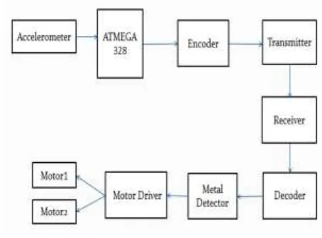
The project Gesture Controlled Metal Detecting Robot includes a lot of mechanical and electronic components. All these components should be arranged in a sequential order to obtain the output. Following are the components required for the project. Accelerometer (ADXL345), Arduino (AtMega 328P), RF Module (TWS 434 & RWS 434),Encoder(HT12E) & Decoder(HT12D), Motor Driver (L293D), DC motors (100 rpm), Chassis, Transistor (BC547), Diode (IN4148), Led, Inductor, Jumper wires, Batteries (9v), Voltage Regulator(7805), few Capacitors, few Resistors, Connecting wires, Vector Board, Buzzer.
Block Diagram:
Figure: 3.1.2 Block Diagram of Proposed System
Hardware Implementation
[image:2.612.329.556.440.608.2]International Journal of Emerging Technology and Advanced Engineering
Website: www.ijetae.com (ISSN 2250-2459, UGC Approved List of Recommended Journal, Volume 8, Issue 4, April 2018)84
It is reliable, flexible, easy to use hardware and software. It can sense the changes in environment provided by the sensors.Accelerometer:
The ADXL345 is a small, thin, low power, complete 3-axis accelerometer with signal conditioned voltage outputs. It consists of 6 pins vcc , ground, X-axis, Y-axis, Z-axis pins. But here we use only two axis X, Y. The variation in hand moment creates a voltage change in capacitor of accelerometer. According to the values of it code should be modified.
Encoder:
Here, HT12E is 212 series encoder is used. It is used to
covert parallel data to serial data. It consists of 18 pins. Pin(1-9) and 14 are connected to ground. Pin number 10,11,12,13 of encoder are connected to 3,4,5,6 of Arduino Uno board respectively. A 1M ohm resistor is used in encoder circuit.HT12E is used as encoder circuit.
Decoder:
HT12D, series decoder is used which is capable of decoding information that consists of N-address bits. It is used to covert serial data to parallel data It consists of 18 pins. Pin (1-9) connected to ground. Pin number 10,11,12,13 of decoder are connected to 10, 15, 7, 2 of Motor driver (L293D) respectively. A 51 K ohm resistor is used in decoder circuit.HT12D is used as decoder circuit.
RF Transmitter And Receiver Module:
RF stands for radio frequency. It is available in different operating frequencies and with different operating range. We have used 433 MHz RF Transmitters used here are TWS434, receiver RWS434 Tx/Rx module. RF module is often used along with a pair of encoder and decoder. It can transmit the signal up to 100m of range at rate of 1 Kbps to 10 Kbps.
Transmitter module consists of 4 pins (GROUND, VCC, DATA, ANTENNA). DATA pin is connected to encoder (pin 17). A 17 cm single strand wire antenna is used which is connected to antenna pin of Tx module. Transmitter receives serial data and transmits RF signal wirelessly to the receiver through this antenna. Receiver module consists of 8 pins. 3 ground pins, 2 VCC pins, 2 DATA pins and 1 antenna pin. DATA pins are connected to decoder (pin 14). In this module also, a 17 cm single strand wire antenna is used for receiving RF signal from transmitter.
The length of the antenna is determined according to the frequency range of RF module.
Wavelength, λ = speed of light (c) / frequency (f)
= 3×10⁸ / 433×106 m = 0.69284 m
So, Antenna length = λ/4
= 0.69284/4 m
= 0.1732 m ≈ 17 cm
Antenna length of RF transmitter =17cm
Motor Driver:
We have used L293D IC which is 16 pin DIP package motor driver having 4 input pins, 4 output pins, 4 VCC pins and 4 ground pins. All 4 input pins are connected to the output pins of decoder IC. And 4 output pins are connected to the DC motors of robot. We have connected all 3 VCC pins to 5V DC supply and 9V DC supply to pin 8.
DC Motor:
DC motor is an electrical device used to rotate wheels of robot when connected to motor driver.
Design And Working:
The transmitter prototype is kept on the palm and the receiver prototype ( i.e robot) moves according to the palm movement. This project explains about the 5 different gesture position of the hand i.e stop condition, forward movement, backward movement, moves towards right and moves towards left.
Stop Condition: When the accelerometer is parallel to the horizontal plane of ground, all the output pins of decoder (13, 12, 11, 10) are set to high which makes the robot get to stop mode.
Forward Movement: When the accelerometer is tilted to forward, two output pin of decoder (13, 11) are set to low and other two output pin of decoder (12, 10) are set to high. This condition commands the robot to move in forward direction.
Backward Movement: When the accelerometer is tilted towards backward direction, two output pin of decoder (12, 10) are set to low and other two output pin of decoder (13, 11) are set to high. This condition commands the robot to move in backward moment,.
International Journal of Emerging Technology and Advanced Engineering
Website: www.ijetae.com (ISSN 2250-2459, UGC Approved List of Recommended Journal, Volume 8, Issue 4, April 2018)85
Moves Towards Left: When the accelerometer is tilted towards left, two output pin of decoder (12, 11) are set to high and other two output pin of decoder (13, 10) are set to low. This condition commands the robot to move towards left.
The robot controlled by gesture is used to move to the doubtful area, when it detects the metal the circuit of metal detector will be closed circuit and indication of detection of metal is identified by using buzzer/led. The flow of current is happened when mutual induction between coil and metal happens. Thus detection of metal can be done.
VI. SOFTWARE IMPLEMENTATION OF GESTURE
CONTROLLED METAL DETECTING ROBOT
Software Setup Requirements:
Arduino IDE, Personal Computer, Arduino files, Power Jack, Cable
ARDUINO IDE:
IDE: Integrated Development Environment.
Arduino UNO consists of both a circuit board(often
referred to as a AtMega328P microcontroller) and a piece of software, or IDE (Integrated Development Environment) which runs on personnel computer, used to write and upload computer code to the physical board.
Writing Sketches
Programs written using Arduino Software (IDE) are called sketches. These sketches are written in the text editor and are saved with the file extension.ino. The editor has features for cutting/pasting and for searching/replacing text. The message area gives feedback while saving and exporting and also displays errors. The console displays text output by the Arduino Software (IDE), including complete error messages and other information. The bottom right hand corner of the window displays the configured board and serial port. The toolbar buttons allow you to verify and upload programs, create, open, and save sketches, and open the serial monitor.
VII. CONCLUSION
Robots are examples of programmable automation, however they are also used in flexible or even fixed automation systems. The two reasons for selecting a robot to operate in a production line are first to reduce lab. The costs and second to perform work that is boring, unpleasant or hazardous for human beings.
Robot can perform repetitive tasks at a steady place, be programmed to achieve and perform deferent unpleasant tasks, operation for long period without rest or break period, and response in automation manufacturing operatio n on a continuous basis. Robot technology is an applied science that is referred to as a combination of machine tool fundamentals and computer application, the variety of technical features about the way a robot is construction and works and the factors that’s influence its selection robot system are usually classified as low technology and high technology groups.
The capacity of a robot to position and oriented the end of its arm with accuracy and repeatability is an important control attribute. Among the important properties of a robot to properly regulate its motion are:
• Stability
•Control Resolution • Spatial Resolution • Accuracy
• Repeatability
• ComplianceProgramming is the process of preparing a det ailed sequence of operating instruction to solve a particular problem, testing it to ensure its accuracy, and preparing documentation to be run on a digital computer. Robot programming26can be defined as a path in space through which the manipulator is directed to move. A program is a logically arranged set of programming instruction. The capabilities of a robot operating system depend on the type of controller, the arm configuration and the method used to train the robot.
VIII. FUTURE SCOPE
International Journal of Emerging Technology and Advanced Engineering
Website: www.ijetae.com (ISSN 2250-2459, UGC Approved List of Recommended Journal, Volume 8, Issue 4, April 2018)86
REFERENCES[1] http://www.ijesrt.com [2] http://www.quora.com
[3] Fairall, John (2002). An Introduction to low power radio. RF Solutions Ltd. ISBN 978-0-9537231-0-2.
[4] Grosvenor, Edwin S. and Wesson, Morgan. Alexander Graham Bell: The Life and Times of the Man Who Invented the Telephone. New York: Harry N. Abrahms, Inc., 1997. ISBN 0-8109-4005-1. [5] Colin King (Editor), Jane's Mines and Mine Clearance, ISBN
0-7106-2555-3
[6] Graves M, Smith A, and Batchelor B 1998: Approaches to foreign body detection in foods, Trends in Food Science & Technology 9 21-27
[7] G. R. S. Murthy, R. S. Jadon. (2009). “A Review of Vision Based Hand Gestures Recognition,”International JThenal of Information Technology and Knowledge Management, vol. 2(2), pp. 40-410. [8] Wikipedia Website.
[9] S. Mitra, and T. Acharya. (2007). “Gesture Recognition: A Survey” IEEE Transactions on systems,Man and Cybernetics, Part C: Applications and reviews, vol. 37 (3),pp. 311-324, doi:10.1109/TSMCC.2007.893280.