International Journal of Emerging Technology and Advanced Engineering
Website: www.ijetae.com (ISSN 2250-2459,ISO 9001:2008 Certified Journal, Volume 5, Issue 7, July 2015)
A Study on Dynamic Response of 20 Storey RC Structure
Considering Mass Irregularity
George Joseph Edward
1, Dr. G.Mohan Ganesh
2, Dr. A.S.Santhi
31SMBS, Structural Engineering Division, Vellore Institute of Technology University, Tamil Nadu, Vellore- 632014, India
2,3Professor, SMBS, Structural Engineering Division, Vellore Institute of Technology University, Tamil Nadu, Vellore- 632014, India
Abstract-- This paper deals with a detailed study on
response behaviour of a vertically irregular structures when subjected to an earthquake excitation. Vertical irregularities due to difference in mass ratio of adjacent floors considered in this study. Irregular structures are designed by incorporating irregularity effects on 20 storey regular structure designed as per IS 1893-2002. Time history analysis was carried out using building software package ETABS -V.9 on all structures with a input ground motion corresponding to El Centro earthquake. The response of the structures due to mass irregularity at different story levels are been studied considering lateral displacement of stories offered by the irregular structures as the parameter for the study. It was found from this study that as the increased mass the floors demands more drift than the regular structure of same configuration. Increased mass ratio of 1.7 to 5 were considered for the study. As mass ratio increases in a particular storey, a noticeable variation of displacement occurs in the neighbour floors. For lesser mass ratios at lower storeys experienced more displacement demand than the same mass ratios present at top storeys. when the mass ratio increased top storeys experienced more displacement demand than the bottom storeys. Also for mass irregular structures were performed more critical with the presence of increased mass at top at lower storeys, than middle storeys.
Keywords: Irregular tall RCC structures, Vertical mass
irregularity, Time history analysis, Lateral storey displacement demand.
I. INTRODUCTION
Dynamic analysis in an irregular structure, whether irregular in plan or elevation is very essential as it deals with effects on the structures when it is influenced by a load actions having high acceleration and requires an immediate response to the system. Weakness points in the structure creates the way to its failure. Structures having vertical irregularities results in the discontinuity in structures will be a cause of weakness points. No structures are perfectly regular, because of intentional or accidental distribution of mass, stiffness, strength, configuration throughout the floors or the combination of these in horizontal and vertical directions.
Also some of the structures made of high degree of irregularity for aesthetic or thematic importance in the present scenario, these structures behave significantly different from that of a nominally regular structure. This characteristics of irregular structures results in high demand and less safe structures, shows chance of collapse at a particular combination of loading. So they need a realistic structural analysis procedure like 3D elastic time history analysis as it provides a low cost, time saving analysis.
II. LITERATURE REVIEW
Magliulo et al.(2002), studied on 5,9 storey RC frame according to EC8. Irregularities due to mass, stiffness, strength were treated separately. He studied about the suitability criteria provide by different codes, by investigating the actual increase in inelastic demands of the models considered.
Results suggested that international codes are failed to analyse the irregular status of a structure in mass and stiffness criteria. They also suggested that variation n mass do not necessarily result in increase in plastic demands and it was found that only over strength of beams results in increased plastic demands, while over strength in columns, and its variation along vertical influences little.
Sadashiva et al.(2008), developed an efficient and simple methodology to evaluate and quantify the mass irregularity effects on the structure. Irregularities at bottom, mid height, top of the 3 storey and 9 storey structures were considered. Taking Drift demand as a parameter for designing, they suggests how to select a mass ratio for the required drift demand consideration.
CONSIDERTION OF MASS IRREGULARITY AS PER IS 1893-2002
As per IS 1893-2002, Part-1; Clause. 7.1, mass irregularity is supposed to exist when the floor mass relative to the adjacent floor is 150% of the considered.
International Journal of Emerging Technology and Advanced Engineering
Website: www.ijetae.com (ISSN 2250-2459,ISO 9001:2008 Certified Journal, Volume 5, Issue 7, July 2015) Dynamic Analysis should be performed for regular
buildings with a height greater than 40m height and in case of irregular buildings with a height greater than 12 m heights in zone IV and zone V, and those greater than 40m in height in zones II and III. Dynamic analysis may be performed either by the time history method or by the response spectrum method. In either method, design base shear compared with base shear calculated with equivalent static analysis.
III. STRUCTURAL MODELLING AND DESIGN
CONSIDERATION
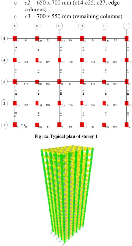
Twelve 20 storey three dimensional reinforced concrete moment resisting framed structures were designed according to the requirements of IS 1893-2002 (Fig:1a,1b), Part 1 seismic code, with a zone factor of 0.24, soil type II, importance factor of 1, response reduction factor 5, considered for the study.
20 RC moment resisting frame structures considered for this study. Regular structure designed as per IS 1893-2002. 8 mass irregular structures were created having mass ratio of 1.7 at 1st, 2nd, 3rd, 4th, 5th, 10th, 15th, 20th floors respectively. Similarly 12 more mass irregular structure were created having mass ratio of 2.4 at 2nd, 3rd, 4th, 5th, 10th, 15th, 20th floors and structures having mass ratio of 5 at 2nd, 5th, 10th, 15th, 20th floors respectively and compared the lateral storey displacement behaviour of every structures with regular structure. Each mathematical models considered for this study were developed with ETABS V9.5.
Specification of structure considered are Live load - 2 KN/m2 on 21floor,
4KN/m2 on 1 to 20 floor. Compressive strength of concrete
- 30 M Pa
Yield strength of steel - 415 M Pa. Height of each storey - 3 m. Number of bays in X direction
- 5bays of 4.5m. Number of bays in Y direction
- 4 bays of 3.6 m. Sizes of columns and beams considered (Fig.1)
o b 1 - 450 x 650mm (exterior beams, B1-B27).
o b2 - 450 x 650 mm(interior beams, B28-B49).
o c1 - 750 x 800 mm (corner columns, c1-c9, c11-c13).
o c2 - 650 x 700 mm (c14-c25, c27, edge columns).
[image:2.612.333.555.135.547.2]o c3 - 700 x 550 mm (remaining columns).
Fig :1a Typical plan of storey 1
Fig:1b. 3D elevation of structure considered
International Journal of Emerging Technology and Advanced Engineering
Website: www.ijetae.com (ISSN 2250-2459,ISO 9001:2008 Certified Journal, Volume 5, Issue 7, July 2015) IV. DYNAMIC ANALYSIS CONSIDERED
Inelastic time history analysis (ITHA)done on the structures considered in order to find out the peak inter storey drift ratio. Structures are subjected to a scaled ground motion corresponds to El centro earthquake data using the ETABS computer program, having 0.6 PGA, with 210 output steps, 0.001 time step size.
Incorporation of Irregularities and design criteria
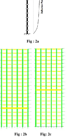
[image:3.612.363.529.108.305.2]Mass irregularity - Inclusion of a mass ratio of 1.7, 2.4 on 5th, 10th, 15th, 20th storey of regular building on the logic of providing 2 m depth water tank and on these floors creates mass irregularity for mass ratio 1.7 and additional dead load of 20 kN/m2, 60 kN/m2 creates a mass ratio of 2.4 and 5 respectively. as an example, as per IS 1893 provision. Stiffness constant model (SC model) was selected for study which will have a deflection pattern as per Fig : 2
Fig : 2a
Fig : 2b Fig: 2c
Fig : 2d Fig : 2e
Fig. 2 Deformed shape for structural configuration and mass irregularity at different levels respectively.
Displacement in Y direction is considered, as the stiffness of the structure in y direction is more critical. Maximum drift obtained after the Time history analysis is compared against the same of regular structure.
V. DISCUSSIONS AND RESULTS
Comparison between the ITHA results of Mass Irregularity structures
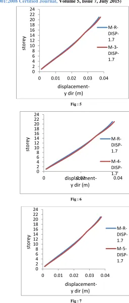
In order to find out the drift demand of the structure due to presence of difference in mass of the storey, a 20 storey regular structure having no mass irregularity taken as the reference and peak storey displacement of regular structure is plotted.
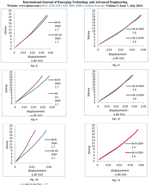
Figure 3 represents the behaviour of deviation of maximum storey displacement of the regular structure in y direction, as this direction is more critical since it has lesser number of bays. In figures 4 to 10 the peak storey displacement of the structure having mass ratio 1.7 at 2nd , 3rd, 4th, 5th, 10th, 15th, 20th respectively compared with the Fig 3 plot. from Fig 4 increased mass ratio at 2nd storey creates an increased displacement demand than the regular structure. And this behaviour increases till 5th floor and it decreases.
[image:3.612.99.240.355.641.2]International Journal of Emerging Technology and Advanced Engineering
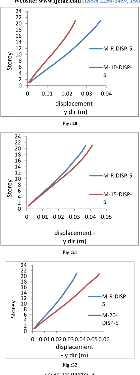
Website: www.ijetae.com (ISSN 2250-2459,ISO 9001:2008 Certified Journal, Volume 5, Issue 7, July 2015) When mass ratio increases from 2.4 to 5 top storey
experienced more displacement demand than the lower storeys with considerable increase in storey displacement than the regular structure.(Fig :18-22).
----M-R-DISP-1.7 indicates storey displacement of mass regular structure considered for 1.7 mass ratio irregularity.
[image:4.612.293.549.121.723.2]----M-5-DISP-1.7 indicates displacement of mass irregular structure having mass irregularity on 5th storey
Fig : 3
Fig : 4
Fig : 5
Fig : 6
Fig : 7 0
2 4 6 8 10 12 14 16 18 20 22 24
0 0.01 0.02 0.03 0.04
M-R-DISP
Sto
rey
displacement - y
dir (m)
0 2 4 6 8 10 12 14 16 18 20 22 24
0 0.01 0.02 0.03 0.04 M-R- DISP-1.7
M-2- DISP-1.7
displacement
- y dir (m)
sto
rey
0 2 4 6 8 10 12 14 16 18 20 22 24
0 0.01 0.02 0.03 0.04 M-R- DISP-1.7 M-3- DISP-1.7
displacement-
y dir (m)
sto
rey
0 2 4 6 8 10 12 14 16 18 20 22 24
0 0.02 0.04
M-R- DISP-1.7
M-4- DISP-1.7
displacement-
y dir (m)
sto
rey
0 2 4 6 8 10 12 14 16 18 20 22 24
0 0.01 0.02 0.03 0.04
M-R- DISP-1.7 M-5- DISP-1.7
displacement-
y dir (m)
sto
[image:4.612.52.288.227.582.2]International Journal of Emerging Technology and Advanced Engineering
[image:5.612.54.554.104.723.2]Website: www.ijetae.com (ISSN 2250-2459,ISO 9001:2008 Certified Journal, Volume 5, Issue 7, July 2015)
Fig : 8
Fig: 9
Fig : 10
(1) MASS RATIO - 1.7
[image:5.612.331.551.127.701.2]Fig: 11
Fig : 12
Fig : 13 0
2 4 6 8 10 12 14 16 18 20 22 24
0 0.01 0.02 0.03 0.04 M-R- DISP-1.7
M-10- DISP-1.7
displacement-
y dir (m)
sto
rey
0 2 4 6 8 10 12 14 16 18 20 22 24
0 0.01 0.02 0.03 0.04 M-R- DISP-1.7
M- 15- DISP-1.7
displacement
- y dir (m)
sto
rey
0 2 4 6 8 10 12 14 16 18 20 22 24
0 0.02 0.04
M-R- DISP-1.7 M-20- DISP-1.7
displacement-
y dir (m)
sto
rey
0 2 4 6 8 10 12 14 16 18 20 22 24
0 0.01 0.02 0.03 0.04
M-R-DISP-2.4
M-2-DISP-2.4
Sto
rey
displacement
- y dir (m)
0 2 4 6 8 10 12 14 16 18 20 22 24
0 0.01 0.02 0.03 0.04 0.05 M-R-DISP-2.4
M-3-DISP-2.4
Sto
rey
displacement -
y dir (m)
0 2 4 6 8 10 12 14 16 18 20 22 24
0 0.01 0.02 0.03 0.04
M-R-DISP-2.4
M-4-DISP-2.4
Sto
rey
International Journal of Emerging Technology and Advanced Engineering
Website: www.ijetae.com (ISSN 2250-2459,ISO 9001:2008 Certified Journal, Volume 5, Issue 7, July 2015)
Fig: 14
Fig: 15
Fig: 16
Fig: 17
(2) MASS RATIO - 2.4
Fig:18
Fig: 19 0
2 4 6 8 10 12 14 16 18 20 22 24
0 0.01 0.02 0.03 0.04
M-R-DISP-2.4
M-5-DISP-2.4
Sto
rey
displacement -
y dir (m)
0 2 4 6 8 10 12 14 16 18 20 22 24
0 0.01 0.02 0.03 0.04 M-R-DISP-2.4
M-10-DISP-2.4
Sto
rey
displacement
- y dir (m)
0 2 4 6 8 10 12 14 16 18 20 22 24
0 0.01 0.02 0.03 0.04
M-R-DISP-2.4
M-15-DISP-2.4
Sto
rey
displacement -
y dir (m)
0 2 4 6 8 10 12 14 16 18 20 22 24
0 0.01 0.02 0.03 0.04
M-R-DISP-2.4
M-20-DISP-2.4
Sto
rey
displacement -
y dir (m)
0 2 4 6 8 10 12 14 16 18 20 22 24
0 0.01 0.02 0.03 0.04 0.05 M-R-DISP-5
M-2-DISP-5
Sto
rey
displacement
- y dir (m)
0 2 4 6 8 10 12 14 16 18 20 22 24
0 0.01 0.02 0.03 0.04 M-R-DISP-5
M-5-DISP-5
Sto
rey
International Journal of Emerging Technology and Advanced Engineering
[image:7.612.56.281.122.723.2]Website: www.ijetae.com (ISSN 2250-2459,ISO 9001:2008 Certified Journal, Volume 5, Issue 7, July 2015)
Fig: 20
Fig :21
Fig :22
(3) MASS RATIO -5
VI. INTERPRETATION OF RESULTS
The inter storey drift ratio of irregular structures shows much deviation according to the different levels of irregularity. The difference in mass ratio at the storey 1 and storey 20 shows maximum drift demand than the between storeys. At storey 10 and 15 shows less displacement demand than the regular structure. Also when the inter storey drift ratio of individual storey considered, there is a considerable decrease in drift demand towards the upper middle stories (7-15 storeys).
When the mass ratio increased from 1.7 to 5, a drastic increase in the peak inter storey drift ratio can be seen. Higher mass ratio at bottom and top storeys makes a tendency to produce higher drift demand. Again the drift demand increases at the 15th floor by with increase in mass ratio from 2.4 to 5
VII. INFERENCE AND CONCLUSION
As per the results obtained from the analysis done, it is inferred that the response of a structure due to the presence of mass irregularity depends on the mass ratio adopted, level of irregularity. It can be easily used for the direct evaluation of the behaviour of drift variation corresponding to the mass ratio levels.
This study tried to give a better quantitative understanding of the effect of mass ratio on different levels of building in the terms of peak storey displacement of the structure. Here only 3 mass ratios are considered. This study can also extend by including more mass ratios of specific intervals.
REFERENCES
[1] Sadashiva VK, MacRae GA, Deam BL [2010], Simple methods to evaluate structural irregularity effects”- New Zealand society of Earthquake Engineering Conference, Paper no-12.
[2] Magliulo G, Ramasco R, Realfonzo R [2002],"A critical review of siesmic code provisions for vertically irregular frames” - 3rd European workshop on the seismic behaviour of irregular and complex structures- Vol. 6 ; pg :285-308.
[3] Habibi A. Asadi K [2013], Seismic performance of RC frames irregular in elevation designed based on Iran seismic code - International Journal of Rehabilitation in Civil Engineering -Vol. 1, Issue. 2(2013); pg: 40 – 55.
0 2 4 6 8 10 12 14 16 18 20 22 24
0 0.01 0.02 0.03 0.04 M-R-DISP-5
M-10-DISP-5
Sto
rey
displacement -
y dir (m)
0 2 4 6 8 10 12 14 16 18 20 22 24
0 0.01 0.02 0.03 0.04 0.05 M-R-DISP-5
M-15-DISP-5
Sto
rey
displacement -
y dir (m)
0 2 4 6 8 10 12 14 16 18 20 22 24
0 0.01 0.02 0.03 0.04 0.05 0.06 M-R-DISP-5
M-20-DISP-5