Image Compression using CDF5/3 Wavelet Transform
Coupled with Bit Plane Algorithm
Anurodh Kumar
Research scholar
NIIST-Bhopal
Bhopal-462023, India
RajeevThakur
Asst. Professor
NIIST-Bhopal
Bhopal-462023, INDIA
Lalit Jain
Asst. Professor
NIIST-Bhopal
Bhopal-462023, INDIA
ABSTRACT
The near future of image processing techniques state the compatibility issues of applied algorithms with storage techniques and data transmission across noisy environment. Image compression is a vital element that is employed due to its characteristics of image size reduction without considerable data loss. This paper employs an SAR image compression technique based on CDF 5/3 in unison with bit plane algorithm. The CDF 5/3 encodes the real images converted by fast Fourier transform (FFT). The performance analysis is observed by changing in BPP (Bit per pixel) for a given image and based on varying BPP peak signal-to-noise ratio (PSNR) and (Mean square Error) MSE.
General Terms
Image processing, SAR image, wavelet transform, Directional lifting wavelet transform.
Keywords
Cohen,Daubechies and Feauveau (CDF),Peak signal to noise ration(PSNR),Mean square error(MSE).
1.
INTRODUCTION
The ease of data handling and flexibility of information transmission have transformed the methods of digital communication in almost every sector. The internet is flooded with volumes of data and more and more information is processed, stored and transmitted in high speed over networks. While preparing for such transformation to communication revolution, one has to be prepared with image quality and maintain coronary angiograms and ventriculograms. An example of data transmission of high resolution videos is presented in [1]. The example demonstrates that approximate 30 Megabytes has to be supported. Computing techniques that would considerably reduce the image size that occupies less space and bandwidth for transmission over networks form an active research .Image compression deals with reducing the amount of data required to represent a digital image [1]. Compression and the amount of distortion in the reconstructed image [2].
As a rapidly developing branch of applied mathematics began in the late 1980s, wavelet transform is certainly a milestone in the history of traditional Fourier analysis. Meanwhile, it has become a powerful tool in the realm of digital image compression. The main advantage of wavelet transform over discrete cosine transform (DCT) is that it has both time and
Daubechies and Feauveau) 5/3 bi-orthogonal wavelet, without standing transform properties, have been wildly used in many areas including the new generation of static image compression standard JPEG2000. The SAR image compression technique has broader scope for compression with varied affliction against like security for defense in noisy channels. The images having amplitude and phase are first-level of complex SAR image systems.
Currently, most compression algorithms of complex SAR image adopt the traditional wavelet transform. However, for the complex SAR images, which are rich in edges and texture, traditional wavelet transform does not show efficient representation. Dong et al. [3] proposed an algorithm which extracted edges of SAR image with wedge let transform and encoded the edges and texture separately. Li et al. [4] used 2-D oriented wavelet transform for remote sensing compression. The SAR images used in [3], [4] are not complex SAR images. The spatial-domain directional wavelet, such as directional lifting wavelet transform (DLWT), employs direction prediction for wavelet decomposition, which adapts the wavelet transform direction to the image edges. DLWT [5] – [7] integrates spatial direction prediction into the wavelet transform lifting framework, provides an efficient. Mohammed Hamzah Abed et al. use a modified version of SPIHT for two dimensional signals which is lossless [8]. G.Chenchu Krishnaiah et al. performs 9/7 and 5/3 wavelets on photographic images (monochrome and color) and estimated Peak Signal to Noise Ratio (PSNR) [9]. J. Maly et al. Proposes an implementation of discrete-time wavelet transform based image codec using Set Partitioning in Hierarchical Trees (SPIHT) coding in the MATLAB environment. The results show that the CDF 5/3 perform best results among all tested wavelet families [10].
In our work we have selected SAR image because it has large scope for compression and this image has varied affliction like a security system for defence, for natural climatic etc. The phase information is crucial for sensitive applications like interferometry and moving target detection. Hence, the normal image compression is reasonably different with SAR image compression as this scheme seeks high phase information accuracy and amplitude fidelity.
two coding schemes show significant performance gain not only in amplitude peak signal-to-noise ratio (PSNR) but also in mean square error (MSE).
The remainder of this paper as follows: Section 2 describes the technique of wavelet transformation process that is used later in CDF 5/3 wavelet transformation. Overall proposed scheme is depicted in section 3. The 4 section of paper describes the quad-tree segmentation and Bit plane encoding in section 5. Section 6 is mathematical approach of CDF 5/3 tap filters followed by results in 7 section. Section 8 summarizes the paper.
2.
DIRECT LIFTING WAVELET
TRANSFORM FOR COMPLEX SAR
IMAGE
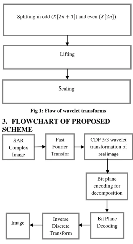
The wavelet transform (WT), in general, produces floating point coefficients. Although these coefficients are used to reconstruction original image perfectly in theory, the use of finite precision arithmetic and quantization results in a lossy scheme. The lifting scheme based wavelet Transform can be implemented as shown in fig.1 for reducing computational complexity. Only the decomposition part of WT is depicted inFig.1 because the reconstruction process is just the reverse version of Fig.1. The lifting-based WT consists of splitting, lifting, and scaling modules and the WT is treated as prediction-error decomposition. It provides a complete spatial interpretation of WT.
2.1. Splitting
In this stage the input signal is divided into two disjoint sets, the odd
(𝑋[2𝑛 + 1])
and the even samples(𝑋[2𝑛])
.2.2. Lifting
In this module, the prediction operation P is used to estimate
𝑋
0(𝑛)
from𝑋
𝑒(𝑛)
and results in an error signal𝑑(𝑛)
. Then we update𝑑(𝑛)
by applying it to the update operation U, and the resulting signal is combined with𝑋
𝑒(𝑛)
to𝑆(𝑛)
estimate, which represents the smooth part of the original signal.2.3. Scaling
[image:2.595.312.539.66.481.2]A normalization factor is applied to
𝑑(𝑛)
and𝑠(𝑛)
, respectively.In the even-indexed part𝑆(𝑛)
is multiplied by a normalization factor𝐾
𝑒 to produce the wavelet sub-band𝑋
𝐿1. Similarly in the odd-index part the error signal𝑑(𝑛)
is multiplied by𝐾
0 to obtain the wavelet sub-band𝑋
𝐻1. The output result is𝑋
𝐿1 and𝑋
𝐻1 by using the lifting-based WT are the same as those of using the convolution approach for the same input.Fig 1: Flow of wavelet transforms
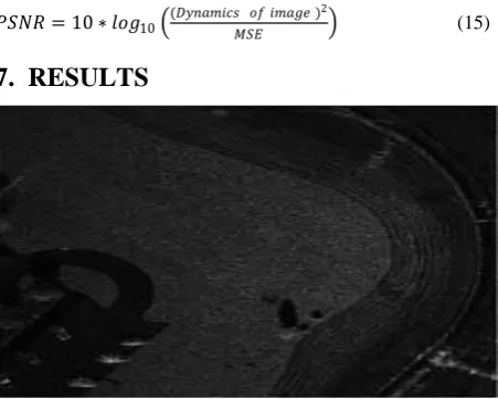
3.
FLOWCHART OF PROPOSED
SCHEME
Fig2: procedure for image compression
The initial step of image compression is the selection of image that is passed through 1-D Fast Fourier Transform (FFT). The negative frequency band is shifted to positive frequency band that increases the original bandwidth of signal to 200% and original frequency signal is focused on positive frequency band. Second, do 1-D IFFT transform and get a complex signal with data volume doubled; lastly, characterize the complex signal with its real part as the imaginary part and the real part of the complex signal fulfill the Hilbert transform. The spectrum movement is corresponding to supplement zeros on the negative side of the frequency signal and creates the bandwidth doubled; so, the complex signal which is the resultant signal of the inverse FFT transform is corresponding to interpolate the complex SAR image by every two pixels on the dimension of transform.
SAR Complex
Image
Image
Fast Fourier Transfor mmmm
m
CDF 5/3 wavelet transformation of
real image
Bit plane encoding for decomposition
BitPlane Decoding Inverse
Discrete Transform
Splitting in odd (𝑋[2𝑛 + 1]) and even (𝑋[2𝑛]).
Lifting
Fig3: block diagram of FFT
4.
DISTORTION BALANCING VIA
QUAD-TREE SEGMENTATION
The quad-tree segmentation method, a bottom-up algorithm in the unconventional sense, is chosen to construct an optimal quad-tree which balances the distortion from prediction with the rate of coding the segmentation tree (including tree structure and direction of each leaf node). The distortion for representing block 𝑋𝑘 with a single leaf is
𝐷 𝑋𝑘 = 𝑥0 𝑚, 𝑛 − 1/2 𝑥𝑒𝑚 𝑛 𝑑 𝑚, 𝑛 + 𝑥𝑒𝑑 𝑚 + 1, 𝑛 (1)
Where 𝑚 and 𝑛 indicate the indexes of row and column, respectively, 𝑥0 𝑚, 𝑛 denotes odd pixel in the block, 𝑥𝑒𝑑 𝑚, 𝑛 and 𝑥𝑒𝑑 𝑚 + 1, 𝑛 are even pixels in the direction 𝑑. As the quadtree structure is encoded with one bit per node, the rate for representing block 𝑋𝑘 with a single leaf is
R(Xk ) = 1+R(d - dp) (2) Where 𝑅(𝑑 − 𝑑𝑝) denotes the number of bits to encode the prediction residual, 𝑑𝑝 is the direction predictor. The direction predictor is the dominant direction selected from the direction of adjacent blocks
.
5.
BIT-PLANE CODING
The bit-plane coding is based on decomposing a multilevel (monochrome or color) image into a series of binary images and compressing each binary image by one of several well-known binary compression methods.
The intensities of an m-bit monochrome image can be represented in the form of base-2 polynomial:
𝑎𝑚−12𝑚−1+ 𝑎𝑚 −22𝑚−2+ … . . +𝑎121+ 𝑎020
Therefore, to decompose an image into a set of binary images we need to separate m coefficients of the polynomial into m 1-bit planes. The lowest order bit-plane (corresponds to the least significant bit) is generated by 𝑎0 bits of each pixel, while the highest order bit-plane contains the m-1 bits. However, this approach leads to the situation, when small changes of intensity can have significant impact on bit-planes. For instance, if a pixel intensity 127 (01111111) is adjacent to a pixel intensity 128 (10000000), every bit will contain a corresponding 0 to 1 (or 1 to 0) transition.
Alternatively, an image can be represented first by an m-bit
𝑔 … 𝑔 𝑔𝑔
𝑔𝑚 −1= 𝑎𝑚−1
where ⊕ denotes the OR operation. The property of this code is that the successive code words differ in only one bit position and small changes in intensity are less likely to affect all m bit-planes.
Fig4: Left two columns: 256-bit original and four most significant binary and Gray-coded bit-planes Right two columns: Four least significant binary and Gray-coded
bit-planes
We notice that the high order bit planes are far less complex than the low-order ones. Also, Gray-coded bit-planes are less complex than the corresponding bit-planes.
Fig4.1:Lossless coding results for binary and gray coded bit plane
The two least significant bits have little apparent structure. Since this is typical for most 8-bit monochrome images, bit-plane coding is usually restricted to 6-bit images.
6.
COHEN-DAUBECHIES-FEAUVEAU
5/3-TAP FILTERS (CDF 5/3)
The Cohen-Daubechies-Feauveau (CDF) 5/3 bi-orthogonal wavelet is a simple wavelet that has two sets of scaling and wavelet functions for analysis and synthesis, hence bi-orthogonality. The CDF 5/3 wavelet has a 5-tap low-pass analysis filter (𝑧) and 3-tap high-pass analysis filter 𝑔(𝑧), hence 5/3. The CDF 5/3 also has a 3-tap low-pass synthesis filter (𝑧) and 5-tap high-pass synthesis filter 𝑔 (𝑧)
JBIG2 lossless
coding results for the binary and
Gray-coded bitplanes
SAR Complex
Image
1-D Fast Fourier Transform
Spectrum Moving
1-D IFFT Extraction of
Analysis Filters: 𝑧 = −18𝑧−2+1
4𝑧 −1+3
4+ 1 4𝑧
1−1 8𝑧
2 (4)
𝑔 𝑧 = −12𝑧−1+ 1 −1 2𝑧
1 (5)
Synthesis Filters: 𝑧 =12𝑧−1+ 1 +1
2𝑧
1 (6)
𝑔 𝑧 = −18𝑧−2−1 4𝑧
−1+3 4−
1 4𝑧
1−1 8𝑧
2 (7)
CDF 5/3 DWT using Lifting Scheme
The low-pass and high-pass analysis filters for the CDF 5/3 are restated below with the high-pass filter translated by 𝑧−1. 𝑧 = −18𝑧−2+1
4𝑧 −1+3
4+ 1 4𝑧
1−1 8𝑧
2 (8)
𝑧−1𝑔 𝑧 = 𝑧−1 −1 2𝑧
−1+ 1 −1
2𝑧
1 = −1 2𝑧
−2+
𝑧−1−1
2 (9)
The poly-phase matrix 𝑃(𝑧) for the CDF 5/3 wavelet is shown below.
𝑃 𝑧 = − 1 8𝑧
−1+3 4−
1 8𝑧
1 −1 2𝑧
−1−1 2 1
4+ 1 4𝑧
1 1 (10)
𝑃 𝑧 = 3 4−
1 8(𝑧
1+ 𝑧−1) −1 2(𝑧
−1+ 1)
1
4(1 + 𝑧1) 1
(11)
The poly-phase matrix can then be factored into two triangular matrices.
𝑃 𝑧 = 1 − 1 2(𝑧
−1+ 1)
0 1
1 0
1
4(1 + 𝑧1) 1
(12)
It is apparent that two lift steps are required, one predict and one update step, to perform the CDF 5/3 DWT. The coefficient for the predict step is:
α = -1/2
and the coefficient for the update step is: β = ¼
Predict and up-date equations for the CDF 5/3 filter are shown below.
𝑃𝑟𝑒𝑑𝑖𝑐𝑡 ∶ 𝑜𝑑𝑑𝑛𝑒𝑤 = 𝑜𝑑𝑑𝑜𝑙𝑑+ −1/2 𝑒𝑣𝑒𝑛𝑙𝑒𝑓𝑡 +
𝑒𝑣𝑒𝑛𝑟𝑖𝑔 𝑡 (13)
𝑈𝑝𝑑𝑎𝑡𝑒 ∶ 𝑒𝑣𝑒𝑛𝑛𝑒𝑤 = 𝑒𝑣𝑒𝑛𝑜𝑙𝑑+ 1/4 𝑜𝑙𝑑𝑙𝑒𝑓𝑡 + 𝑜𝑙𝑑𝑟𝑖𝑔𝑡 (14)
[image:4.595.318.544.506.687.2]The floor function is used for both predict and update equations to provide an integer-to integer transform. The forward CDF 5/3 DWT using the lifting scheme is shown in Figure 5.
Fig 5: Forward CDF 5/3 DWT using Lifting Scheme
6.1. Mean Square Error
The MSE of an estimator is one of various ways to measure the modification between values created by an estimator and the true values of the quantity being projected. MSE calculates the middling of the squares of the "errors." The error is the quantity by which the value created by the estimator varies from the quantity to be projected. The alterationhappenshowing to arbitrariness or owing to the estimator doesn't account for data that could yield a more precise estimate
.
𝑀𝑆𝐸 = 1/(𝑀 ∗ 𝑁) 𝑁 𝑥 𝑖, 𝑗 − 𝑦 𝑖, 𝑗 2 𝑗 =1
𝑀
𝑖=1 (14)
6.2. Peak Signal to Noise Ratio
PSNR is an engineering term for the ratio between the greatest likely power of a signal and the power of corrupting noise that affects the fidelity of its representation. As various signals have a very extensive dynamic range, PSNR is generally conveyed in terms of the logarithmic decibel scale. The PSNR is most commonly used as a measure of quality of reconstruction by lossy compression code (e.g., for image compression).
𝑃𝑆𝑁𝑅 = 10 ∗ 𝑙𝑜𝑔10 (𝐷𝑦𝑛𝑎𝑚𝑖𝑐𝑠 𝑜𝑓 𝑖𝑚𝑎𝑔𝑒 )𝑀𝑆𝐸 2 (15)
7. RESULTS
Table 1.For figure 6
Fig 7: Real part of SAR image
Table2.For figure7
Fig 8: Real part of SAR image
Table3. For figure8
1.0 BPP
Fig8
Base
paper PSNR MSE
63.72 77.7992
71.2894
Fig9: Real part of SAR image
Table4.For figure9
1.0 BPP
Fig9
Base
paper PSNR MSE
Not
available 77.8227
70.9053
Fig10:Real part of SAR image
Table5.For figure10 1.0 BPP
Fig6
Base
paper PSNR MSE
71.20 77.5434
75.6141
1.0BPP
Fig 7
Base
Paper PSNR MSE
74.97 78.2292 64.5699
1.0BPP
Fig 10
Base
Paper PSNR MSE
[image:5.595.337.522.72.210.2]Table6.For fiure11
8. CONCLUSION
The objective of this paper is undoubtedly the improvement of SAR images quality after the compression..We used the CDF Lifting based wavelet transform, coupled with the Bit plane coding. After several applications, we found that this algorithm gives better results as compression to the techniques applied in the base paper. The results obtain from this shows that the value of PSNR is improved as compared to base paper.
The future scope of the presented work can be summarized as following.
The techniques can be extended for video compression.
The techniques can be extended for any other image processing applications for better results.
9
.
REFERENCES
[1] M. Antonini, M. Barlaud, P. Mathieu, I. Daubechies. Image coding using wavelet transform. IEEE Trans. Image Proc., Vol. 5, No. 1, pp.205-220, 1992.
[2] M. Antonini, M. Barlaud, P. Mathieu, I. Daubechies. Image coding using wavelet transform. IEEE Trans. Image Proc., Vol. 5, No. 1, pp.205-220, 1992.
[3] IEEE Trans. Geosci.Remote Sens., vol. 49, no. 1, pp. 236–250, Jan. 2011.
[4] W. Ding, F. Wu, and X. Wu, “Adaptive directional lifting-based wavelet transform for image coding,” IEEE Trans. Image Process., vol. 16, no. 2, pp. 416–427, Feb. 2007.
[5] Y. Liu and K. N. Ngan, “Weighted adaptive lifting-based wavelet transform for image coding,” IEEE Trans. Image Process., vol. 17, no. 4, pp. 500–511, Apr. 2008. [6] X. S. Hou, G. F. Jiang, R. Ji, and C. L. Shi, “Directional
lifting wavelet and universal trellis coded quantization based image coding algorithm and objective quality evaluation,” IET Image Process., vol. 5, no. 8, pp. 693– 702, Dec. 2011.
[7] Mohammed Hamzah Abed, C. Namrata Mahender, “SAR Image Compression using SPIHT Algorithm”, International Journal of Computer Applications (0975 – 8887) Volume 22– No.8, May 2011.
[8] G.Chenchu Krishnaiah, T.Jaya Chandra prasadM.N.giri prasad, “Efficient Image Compression Algorithms Using Evolved Wavelets”, International Journal of Systems and Technologies (ISSN: 0974-5815) Vol.4, No.2, pp 127-146, 2011.
[9] J. Malý, P. Rajmic, “DWT-SPIHT Image Codec Implementation”,
[10] A. Said and W. Pearlman, “A new fast and efficient image codec based on set partitioning in hierarchical trees,” IEEE Trans. Circuits and Syst. for Video Technol., vol. 6, pp. 243–250, Jun1996.
[11] Z. Xiong, K. Ramchandran, and M. Orchard,“Space-frequency quantization for wavelet image coding”. IEEE Trans. Image Processing, vol. 6, no.5, May 1997, 677– 693.
[12] M. Beladgham, A. Bessaid, A. Moulay-Lakhdar, M. Ben Aissa, A. Bassou, “MRI Image compression using biorthogonal CDFwavelet based on lifting scheme and SPIHT coding”Quatrième Conférence International sur le Génie Electrique CIGE’10, 03-04 November 2010. [13] A. Jensen, A.la Cour-Harbo: Ripples in Mathematics,
Springer, 2001. 1.0BPP
Fig10
Base
Paper PSNR MSE