International Journal of Emerging Technology and Advanced Engineering
Website: www.ijetae.com (ISSN 2250-2459,ISO 9001:2008 Certified Journal, Volume 3, Issue 1, January 2013)
211
Root Cause Analysis for Reducing Breakdowns in a
Manufacturing Industry
Kiran M
1, Cijo Mathew
2, Jacob Kuriakose
31
PG Scholar, M A College of Engineering, Kothamagalam, Ernakulam, Kerala
2,3Assistant Professor, M A College of Engineering, Kothamagalam, Ernakulam, Kerala
Abstract – Now a days manufacturing industries are facing a greater competition in the market. Because of this, they try to improve and increase both quality and productivity continuously. One way to increase the productivity is to increase the availability of existing machines; Total productive maintenance aims to increase the availability of existing equipment so no further capital investment is needed. Availability of machines can be increased by reducing the downtime or Breakdowns of the machines.The main objective of this study is to find out the major breakdowns causing production losses to the company and to suggest counter measures by which these problems can be reduced. In the study a Root cause analysis is conducted to find the root cause of breakdowns and some parallel improvement opportunities were also identified for implementation so as to reduce the downtime.
Keywords – Breakdowns, Cause and effect diagram, Pareto Chart, Total productive maintenance, Root cause analysis.
I. INTRODUCTION
The manufacturing industries have gone through significant changes in the last decade. New firms in markets have increased competition dramatically. Most of them focus on product quality, production time and cost of product. Because of these, a company should introduce a quality system to improve and increase both quality and productivity continuously.
Total productive maintenance (TPM) is a methodology that aims to increase the availability of existing equipment hence reducing the need for further capital investment [2, 5]. TPM can be defined in terms of overall equipment effectiveness (OEE) which in turn can be considered a combination of the operation maintenance, equipment management, and available resources [7]. The goal of TPM is to maximise equipment effectiveness [6]. It is a function of availability, performance rate, and quality rate. Of the six major categories of losses that affect OEE, Breakdown loss is used for calculating the availability of equipment.
Root cause analysis (RCA) is a method of problem solving that tries to identify the root causes of faults or problems that cause operating events [1, 3, 9, 10].
RCA practice tries to solve problems by attempting to identify and correct the root causes of events, as opposed to simply addressing their symptoms [8]. By focusing correction on root causes, problem recurrence can be prevented.
A case study is conducted on one of the leading male contraceptive manufacturing industry in the world. The company is in the phase of implementing TPM. So as a fore work to the implementation of TPM, case study, Root Cause Analysis for reducing the breakdowns in the company’s manufacturing unit is conducted. The objective of study is to find out the major breakdowns in the company which causes a production loss and to suggest counter measures to minimize the effect.
The paper is structured as follows. Section 2 gives clear idea of the problem in the industry. Section 3 presents the Root cause analysis of the problem. Parallel improvement opportunities are exposed in Section 4. Finally, Section 5 concludes the study.
II. PROBLEM DEFINITION
Even after producing 24 x 7, the company is not able to meet its demands in the market. So firm has to reduce the unwanted stoppages of production so as to maintain the steady production level and to meet the demands in the market. Production may be stopped due to many reasons like breakdown of machine, maintenance work, labour issues, insufficient material supply, problems in the method of production etc… Excluding all other factors like materials, method, man, etc... It is necessary to reduce the breakdown (down time) of machine or equipment’s in the company for the efficient nonstop production to meet the demands. Breakdowns are the most common causes of efficiency loss in manufacturing. Eliminating unplanned down time is critical to improving Overall Equipment Efficiency. It is not only important to know how much Down Time your process is experiencing (and when) but also to be able to attribute the lost time to the specific source or reason for the loss.
International Journal of Emerging Technology and Advanced Engineering
Website: www.ijetae.com (ISSN 2250-2459,ISO 9001:2008 Certified Journal, Volume 3, Issue 1, January 2013)
212
III. ROOT CAUSE ANALYSISThe Root Cause Analysis is a four-step process involving the following:
1. Data collection 2. Cause charting
3. Root cause identification 4. Recommendation.
A. Data Collection and Analysis
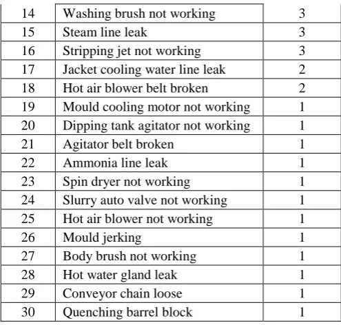
Breakdown data was collected for 8 months (from 01/12/2012 to 02/08/2012) from the shift log book of the company and is tabulated (Tab. 1). The breakdowns and frequency of occurrence are:
TABLEI
BREAKDOWNS OCCURRED AND FREQUENCY
Sl. No. Breakdown occurred Frequency
1 Edge roller not working 98
2 Vulcanization Barrel not working 68
3 Chain slipping 20
4 Mould touching the tank 12
5 Washing machine not working 9 6 Waste water pump not working 8 7 Quenching barrel choot block 7
8 Carry fan not working 6
9 Dehydrator not working 6
10 Slurry pump not working 4
11 Dehydrator chain slip 3
12 Feed valve block 3
13 Stripping line block 3
14 Washing brush not working 3
15 Steam line leak 3
16 Stripping jet not working 3
17 Jacket cooling water line leak 2
18 Hot air blower belt broken 2
19 Mould cooling motor not working 1 20 Dipping tank agitator not working 1
21 Agitator belt broken 1
22 Ammonia line leak 1
23 Spin dryer not working 1
24 Slurry auto valve not working 1
25 Hot air blower not working 1
26 Mould jerking 1
27 Body brush not working 1
28 Hot water gland leak 1
29 Conveyor chain loose 1
30 Quenching barrel block 1
Breakdown data collected consist of all breakdowns that occur in a manufacturing firm. But our area of interest is the breakdown causing production stoppages. Stoppage of one minute causes 140 pieces of products wasted. Calculating the loss in rupees, each product cause a loss of profit of Rs. 4.5/-, i.e., a loss of about Rs. 630/- per minute.
[image:2.595.307.555.132.368.2]The breakdowns causing stoppages of production process were identified from the data. The time spend to rectify the breakdowns was also noted. The Fig. 1 gives the major breakdowns causing production losses.
Fig 1: Pie chart showing breakdowns causing production stoppage
From the chart it is clear that Edge roller breakdown (40%) accounts for the most of the breakdown causing production loss to the company. Vulcanization barrel breakdown (28%), Chain slipping (8%) etc… are other major breakdowns in the company as per the data collected.
The times spend for getting back the equipment for work was also collected and analysed. Fig. 2 gives the percentages of time spend for different breakdown maintenance. The chain slipping (63%) accounts for the major time loss of production. Edge roller breakdown (13%) and slurry pump breakdown (13%) also accounts for a considerable loss of production for the industry. 40%
28% 8%
5% 4% 3%
3% 3% 2% 2% 2%
Breakdowns
Edge roller Vulcanization barrel Chain slipping Mould touching the tank Washing machine Waste water pumpQuenching barrel choot block Slurry pump
[image:2.595.39.289.323.514.2] [image:2.595.131.459.544.639.2]International Journal of Emerging Technology and Advanced Engineering
Website: www.ijetae.com (ISSN 2250-2459,ISO 9001:2008 Certified Journal, Volume 3, Issue 1, January 2013)
[image:3.595.69.266.147.250.2]213
Fig 2: Pie chart showing time spent to rectify breakdowns
For slurry pump breakdown, company have an alternate pump which is used while breakdown of the main pump. In case of vulcanization barrel they go for manual vulcanization while the breakdown. And in the case mould touching the tank they have a readjustment screw for the adjustment. So the other types only accounts for small stoppage rather than a larger time consuming breakdowns.
Considering the frequency of occurrence and the time wasted due to breakdown maintenances, it was identified that chain slipping and edge roller breakdown was the major causes of production loss in the company.
So root cause analysis was conducted identification of root causes of chain slipping and edge roller breakdown.
B. Cause Charting and Root Cause Identification
Cause-and-effect diagrams or Ishikawa diagrams (Fish bone diagram) is one of the seven basic tools of quality, which is used to identify potential factors causing an overall effect [4]. It was used in the study to identify the root cause of the major breakdowns identified in the previous section. A Pareto chart, where individual values are represented in descending order by bars, and the cumulative total is represented by the line. The left vertical axis is the frequency of occurrence, and right vertical axis is the cumulative percentage of the total number of occurrences. The purpose of the Pareto chart is to highlight the most important among a (typically large) set of factors [4, 11]. In quality control, it often represents the most common sources of defects, the highest occurring type of defect.
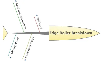
1. Root Cause Identification of Edge Roller Breakdown:
[image:3.595.344.539.227.347.2]Edge roller is unit used to roll up the edges of the product produced in the company. It mainly consists of a pulley belt arrangement, motor, bevel gear, and a long brush mounted on a shaft. The edge roller unit is a major contributor to the time loss to production due to its frequent breakdowns.
Fig 3: Initial cause and effect diagram of edge roller breakdowns
Fig. 3 shows the initial cause and effect diagram of edge roller. The causes of breakdown may be belt loose or lower belt tension, bevel gear dislocation, motor breakdown of the roller and brush damages.
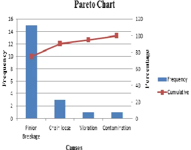
[image:3.595.329.536.491.641.2]A Pareto chart (Fig. 4) was constructed as per the frequency of occurrences of each causes of edge roller breakdown. From the chart it is clear that lower belt tension or belt loose and bevel gear dislocation are the major causes of the breakdown of the edge roller equipment.
Fig 4: Pareto chart of edge roller breakdowns
63% 13%
13% 8%
3%
Time Spend
Chain slipping
Edge roller
Slurry pump
International Journal of Emerging Technology and Advanced Engineering
Website: www.ijetae.com (ISSN 2250-2459,ISO 9001:2008 Certified Journal, Volume 3, Issue 1, January 2013)
[image:4.595.98.496.142.309.2]214
Fig 5: Final cause and effect diagram of edge roller breakdowns
A detailed study was conducted on causes for the edge roller breakdown and final cause and effect diagram is prepared as given in Fig. 5. Reasons for lower belt tension was identified as deterioration, thermal expansion of belt and the regular readjustment made on the machine part. Regular readjustment cannot be rectified since as the mould length varies the edge rolling unit has to be readjusted to obtain the correct rolling thickness. Deterioration and thermal expansion of belt can be overcome by using a higher grade belt than the present one, having a higher temperature range and longer life.
Motor breakdown was caused due to vibration machine, contaminations and the over/under lubrication of bearings of the motor. Brush damages were caused due to deterioration of brush teeth and misalignment of brush with the mould. But this only need a small time to rectify and does not affect the production so much.
The major reason for edge roller was the breakdown caused due to bevel gear dislocation of the machine. Dislocation happens due to overload, tooth breakage of bevel gear, and bearing damages. Bearing damage was due to overheating, contamination of bearings and improper load acting on it. Overload in bevel gear and improper load in bearing was mainly due to the misalignment of shaft. As mentioned earlier there is a need of regular readjustment of the machine as the size of mould varies. If proper alignment checking is done during the adjustment of edge roller the breakdowns can be avoided.
2. Root Cause Identification of Chain Slipping:
[image:4.595.336.531.338.442.2]Conveyor Chain is a major part of moulding machine in the manufacturing plant. This endless chain carries the vertically positioned moulds in the moulding section. Any breakdown to this unit causes the entire stoppage of production.
Fig 6: Initial cause and effect diagram of Chain slipping
[image:4.595.335.528.552.703.2]Fig. 6 show initial cause and effect diagram of chain slipping. The causes of breakdown may be Pinion breakage, vibration of machine, chain loose, and contamination. A Pareto chart (Fig. 7) was constructed as per the frequency of occurrences of each causes of chain slipping. From the chart it is clear that pinion breakage is the major cause of the breakdown due to chain slipping.
International Journal of Emerging Technology and Advanced Engineering
Website: www.ijetae.com (ISSN 2250-2459,ISO 9001:2008 Certified Journal, Volume 3, Issue 1, January 2013)
[image:5.595.84.519.145.334.2]215
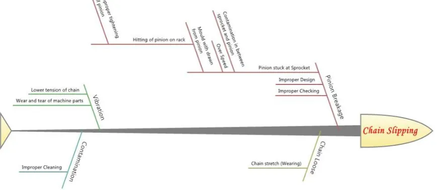
Fig 8: Final cause and effect diagram of chain slipping
A detailed study was conducted on causes for breakdown due to chain slipping and final cause and effect diagram is prepared as given in Fig. 6. Reasons for vibration of the chain were the lower tension of the chain due to its stretching or wearing and wearing of other parts of the moulding machine. Chain becomes loose due to stretching or wearing due to its longer and continuous use. Contamination due to improper cleaning on the equipment was also identified as a reason for chain slipping. These causes can be eliminated by performing proper maintenance techniques like preventive maintenance, planned maintenance etc…
The major reason for chain slipping was the breakdown caused due to pinion breakage in the moulding machine. The different causes of pinion breakage was improper design of pinion, improper checking methods employed for incoming pinion from suppliers, and pinion getting stuck at the sprocket of the machines. By adopting a inspection method for incoming material, the first two causes can be avoided. Pinion get stuck at the sprocket due to contaminations (like lubricant and dust mixture), over speed, and the movement of pinion without mould. Mould gets withdrawn from the pinion due to improper tightening, while entering the rack section. A proper implementation of tightening mechanism can avoid the occurrence of this breakdown.
C. Recommendations
From cause and effect diagram, the root causes of breakdowns caused due to chain slipping and edge roller was identified.
In the case of edge roller, belt deterioration and Improper alignment checking of the unit after readjustment were identified as the root cause for edge roller breakdown. A higher grade belt like EPDM belt, which can withstand higher temperature and longer life, can be used for the purpose. Other cause is improper alignment checking of edge roller, for this, workers should be given proper training for checking the alignment of the edge roller unit.
Root cause for chain slippage was identified as the improper tightening of pinion and the mould. Presently pinion is tightened manually to the mould. So there will be variations in the tightness due to the force applied by human hand. A proper means for tightening should be adopted to avoid this cause for the breakdown due to chain slipping. Using a torque wrench is suggested as a counter measure for avoiding the chain slippage.
IV. PARALLEL IMPROVEMENT OPPORTUNITIES
In the case of edge roller, belt deterioration and Improper alignment checking of the unit after readjustment were identified as the root cause for edge roller breakdown. To avoid this breakdown an improvement in the present setup can be made. By using a direct drive for each edge roller unit, parts like belt, pulley and bevel gear can be avoided from the present setup. Thus avoiding the breakdown caused by belt and bevel gear, which accounts for the most of edge roller breakdowns of the machine.
A.Technical Feasibility
International Journal of Emerging Technology and Advanced Engineering
Website: www.ijetae.com (ISSN 2250-2459,ISO 9001:2008 Certified Journal, Volume 3, Issue 1, January 2013)
216
Speed of motor = 1400rpmGear ratio = 1:10
Torque required = 170Nm Maximum weight permissible = 14kg
Direct drive specification available in the market [12]:
Model =
Unicase helical bevel gear unit (BIM 1040) Make = NordIndia, Pune
Gear ratio = 5.4 – 200 Power range = 0.12 – 9.2kW Torque range = 48 – 670Nm
Fig 10: Direct drive, NordIndia make.
B.Economic Feasibility
Cost of a single direct drive = Rs. 8000/-
Installation cost (for 14 machines) = 14*4000
= 56000/-
Total investment for implementation = 14 * 8000+56000
= Rs. 1, 68,000/-
No. of products produced in 1 minute = 140 in one line
Average no. of breakdowns/month = 15 nos.
Average time taken for rectification = 20 minutes
Loss in profit/product = Rs. 4.50/-
Loss due to breakdown of edge roller (Considering 2 lines of production)
= 280*15*20*4.50 = Rs. 3, 78,000/-
Implementation of direct drive will reduce the breakdown due to edge roller to zero and company can increase their profit.
Increase in profit/month = 378000 – 168000
= Rs. 2, 10,000/-
V. CONCLUSION
The main objective of study was to identify the major breakdowns causing the production loss to the company. Root cause analysis was conducted for the major breakdowns causing production loss to the company. Root causes of breakdowns were identified using cause and effect diagram. Counter measures and parallel improvement opportunities for major breakdowns causing production stoppage was also suggested.
REFERENCES
[1 ] Hicham Jabrouni, Bernard Kamsu-Foguem, Laurent Geneste, Christophe Vaysse “Continuous improvement through knowledge-guided analysis in experience feedback” Engineering Applications of Artificial Intelligence 24 (2011) 1419–1431. [2 ] F.T.S. Chan, H.C.W. Lau, R.W.L. Ip, H.K. Chan, S. Kong
“Implementation of total productive maintenance: A case study” Int. J. Production Economics 95 (2005) 71–94
[3 ] A. Mark Doggett, Humboldt State University, “Root Cause Analysis: A Framework for Tool Selection” Quality Management Journal VOL. 12, NO. 4/ 2005, ASQ
[4 ] Abhishek Jayswal, Xiang Li, Anand Zanwar, Helen H. Lou, Yinlun Huang, “Sustainability root cause analysis methodology and its application” Computers and Chemical Engineering 35 (2011) 2786– 2798
[5 ] Swanson L., “Linking maintenance strategies to performance”. International Journal of Production Economics 70(3), (2001), 237–244.
[6 ] F. Ireland and B.G. Dale “A study of total productive maintenance implementation”, Journal of Quality in Maintenance Engineering, Vol. 7 No. 3, (2001), pp. 183-191.
[7 ] Ki-Young Jeong, Don T. Phillips “Operational efficiency and effectiveness measurement”International Journal of Operations & Production Management, Vol. 21 No. 11,( 2001), pp. 1404-1416.
[8 ] Dr. Anthony Mark Doggett, “A Statistical Comparison of Three Root Cause Analysis Tools” Journal of Industrial Technology, Volume 20, Number 2 - February 2004
[9 ] James J. Rooney and Lee N. Vanden Heuvel, “Root Cause Analysis for Beginners”, Quality Progress Discussion Board, ASQ.
[10 ]Dale H. Besterfield, Carol Besterfield, Glen H. Besterfield & Mary Besterfield, “Total Quality Management”, Person Education (2008 ).
[11 ]Surhone, L., Timpledon, M., & Marseken, S. (2010). “Pareto analysis: Statistics, decision making, Pareto principle, fault tree analysis, failure mode and effects analysis. Pareto distribution”, Wikipedia Betascript Publishing.