Ternary and quadriphase sequence
diffusers
Angus, JAS, Cox, TJ and D'Antonio, P
http://dx.doi.org/10.1121/1.2139632
Title
Ternary and quadriphase sequence diffusers
Authors
Angus, JAS, Cox, TJ and D'Antonio, P
Type
Article
URL
This version is available at: http://usir.salford.ac.uk/421/
Published Date
2006
USIR is a digital collection of the research output of the University of Salford. Where copyright
permits, full text material held in the repository is made freely available online and can be read,
downloaded and copied for noncommercial private study or research purposes. Please check the
manuscript for any further copyright restrictions.
Ternary and quadriphase sequence diffusers
Trevor J. Coxa兲and James A. S. Angusb兲
Acoustics Research Centre, University of Salford, Salford M5 4WT, United Kingdom
Peter D’Antonioc兲
RPG Diffusor System Inc., 651-c Commerce Drive, Upper Marlboro, Maryland 20774
共Received 16 June 2005; revised 25 October 2005; accepted 26 October 2005兲
A room acoustic diffuser breaks up reflected wavefronts, and this can be achieved by presenting a spatially varying surface impedance. In hybrid surfaces, varying impedance is achieved by patches of absorption and reflection, giving reflection coefficients nominally of 0 and 1. These surfaces are hybrids, absorbing some of the incident sound while diffusing any reflected energy. A problem with planar hybrid surfaces is that specular energy is only removed by absorption. By exploiting interference, by reflecting waves out-of-phase with the specular energy, it is possible to diminish the specular energy further. This can be achieved by using a diffuser based on a ternary sequence that nominally has reflection coefficients of 0, −1, and +1. Ternary sequences are therefore a way of forming hybrid absorber-diffusers that achieve better scattering performance without additional absorption. This paper discusses methods for making ternary sequence diffusers, including giving sequence generation methods. It presents prediction results based on Fourier and boundary element method models to examine the performance. While ternary diffusers have better performance than unipolar binary diffusers at most frequencies, there are frequencies at which the performances are the same. This can be overcome by forming diffusers from four-level, quadriphase sequences. ©2006 Acoustical Society of America. 关DOI: 10.1121/1.2139632兴
PACS number共s兲: 43.55.⫺n, 43.20.El 关NX兴 Pages: 310–319
I. INTRODUCTION
Diffusers can be used to improve the acoustics of en-closed spaces to make music more beautiful and speech more intelligible.1Early research in diffusers began by considering nonabsorbing surfaces, such as Schroeder diffusers.2 Recent developments have concerned the development of “diffsorb-ers” of hybrid absorber-diffusers; these are surfaces where partial absorption is inherent in the design, and any reflected sound is dispersed. In hybrid surfaces, wavefront dispersal is achieved via a spatial distribution of impedances, which is achieved by patches of absorbing and reflecting material. These surfaces are hybrids somewhere between pure absorb-ers and nonabsorbing diffusabsorb-ers, usually providing sound dif-fusion at high frequencies, and crossing over to absorption below some cutoff frequency.
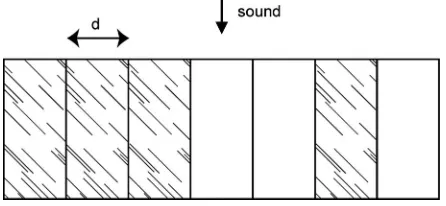
The use of absorptive patches to generate dispersion is not particularly new. In studio spaces, people have been ar-ranging absorption in patches rather than solid blocks for many years. In recent times, however, a new breed of surface has been produced, where the absorbent patches are much smaller, and the arrangement of these patches is determined by a pseudorandom sequence to maximize the dispersion generated. For instance, the binary amplitude diffsorber 共BAD兲panel3–5is a flat hybrid surface with the location of the absorbent patches determined by a maximum length se-quence 共MLS兲. Figure 1 shows a typical construction for a device designed to scatter in a single plane.
A problem with planar hybrid absorber-diffusers is that energy can only be removed from the specular reflection by absorption. While there is diffraction caused by the imped-ance discontinuities between the hard and soft patches, this is not a dominant mechanism except at low frequencies. At high frequencies, when the patch becomes smaller than half the wavelength, the specular reflection is only attenuated by about 6 dB for a surface with 50% absorptive area. To im-prove performance, it is necessary to exploit interference and reflect waves out-of-phase with the specular energy. This can be achieved by using a diffuser based on a ternary sequence. In the next section, a brief outline of a simple theory for sound scattering is given; this is needed to understand the diffuser design. Section III then outlines the principles be-hind the construction of a ternary sequence diffuser. Section IV then details various construction methods that can be used to make the diffusers and also includes some results for the scattering performance based on a simple prediction model. Repeating diffuser units concentrates energy in diffraction lobes, which can degrade scattering performance, conse-quently Sec. V examines how repetition can be avoided in ternary diffusers using modulation techniques. Up to this point, rather narrow and short sequences have been used to outline the general principles. In Sec. VI, longer sequences that are more useful for application are considered and more accurate prediction models are used. For many frequencies, ternary sequence diffusers have improved performance over diffusers based on unipolar binary sequences. However, at even multiples of the design frequency, the performances of the two diffuser types are the same. Consequently, Sec. VII examines how this is solved using quadriphase 共four-level兲 sequences. Up until this point, the paper will only have dealt
a兲Electronic mail: [email protected] b兲Electronic mail: [email protected]
c兲Electronic mail: [email protected]
with diffusers that scatter in a single plane, and so in Sec. VIII appropriate methods for constructing ternary sequence diffusers that scatter hemispherically are given.
II. THEORY
Consider a flat diffuser surface with a distribution of reflection coefficientsRn. The diffuser is illuminated with a
plane wave normal to the surface. When the observer is in the far field, this results in a far-field pressure,p共兲of
p共兲=
兺
n=0 N−1
Rne−jn⍀, 共1兲
where ⍀=kdsin共兲, d is the spacing of the patches 共see Fig. 1兲,kis the wave number, andis the angle of reflec-tion with respect to the normal to the surface of the dif-fuser. This equation is a discrete Fourier transform, which means that the far-field polar pattern is related to the re-flection coefficients by a Fourier transform relationship. What is needed is to find structures with reflection coef-ficients that have uniform magnitude Fourier transforms, such as Schroeder diffusers.2 The Wiener-Khinchin theo-rem states that the squared Fourier transform magnitude of a sequence is equal to the Fourier transform of its autoco-variance共or autocorrelation function兲. Thus a sequence of reflection coefficients whose autocovariance is a Kronecker delta function will form a good diffuser, be-cause the autospectrum will be uniform.
III. A SIMPLE TERNARY DIFFUSER
Figure 1 shows a typical hybrid absorber-diffuser. The hard and soft patches produce reflection coefficients that are nominally either 1 共hard兲or 0 共absorbing兲. By changing the relative proportion of hard and soft patches on the surface, it is possible to control the absorption coefficient. By changing the ordering of the patches, it is possible to control how the reflected sound is distributed. If a periodic arrangement of patches is used, then the autocovariance will contain a series of peaks, and so the autospectrum will be uneven. From Eq. 共1兲, this means that at each frequency the reflected sound will be concentrated in particular directions due to spatial alias-ing; these are grating lobes. If a good pseudorandom sequence is used to choose the patch order, one with a delta-function like autocovariance—say a Barker sequence6—then the scattering will be more even.
However, whatever the arrangement of the patches, at high frequency, the best that can be achieved is an attenua-tion of 7 dB of the specular reflecattenua-tion lobe, because 3 / 7 of the surface forms a flat plane surface that reflects mostly unaltered by the presence of the absorbing material. For the specular reflection direction, = 0, the scattered pressure is simply a sum of the reflection coefficients Rn. So unless
some of these coefficients are negative, the suppression of the specular lobe is limited. Figure 1 is an example of a “unipolar” binary diffuser because the sequence of reflection coefficients is only in one direction with respect to zero; i.e., it is composed of 0’s and 1’s. 共Schroeder’s original maxi-mum length sequence diffuser2 was bipolar, because the bi-nary sequence was composed of −1’s and +1’s兲.
Ternary diffusers offer a chance to introduce some nega-tive reflection coefficients. An example of a ternary diffuser is shown in Fig. 2. The final well has a depth of a quarter of a wavelength at the design frequency, f0, and so at odd
mul-tiples of this frequency the well has a reflection coefficient,
R= −1. Therefore, the surface reflection coefficient distribu-tion is a sequence of −1’s, 0’s, and +1’s. The well produces waves out-of-phase with the sections of the diffuser produc-ing the specular energy 共the patches with R= + 1兲, thus
en-abling better reduction of the specular energy. In this case, the suppression of the specular lobe will be up to ⬇20 log10共7 / 2兲⬇11 dB.
IV. SEQUENCES
[image:3.612.318.555.39.156.2]To compare the performance of unipolar binary and ter-nary sequences, it is necessary to construct some diffusers, and for this sequences with the best patch order are needed. For diffusers with a small number of patches, it is possible to find the sequences with the best autocovariance by an ex-haustive search of all possible combinations using a com-puter. The computer judges the quality of each sequence’s autocovariance using a merit factor.6 For the unipolar case, there can be no cancellation within the autocovariance cal-culation becauseR= 0 or 1; in this case, the merit factor used for optical sequences is appropriate; this is the maximum value of the out-of-phase autocovariance function. For the ternary sequence, there can be cancellation when calculating the out-of-phase autocovariance values, and so the merit fac-tor is the total out-of-phase energy.
FIG. 1. A binary amplitude diffuser where the white patches are made of hard material and are reflecting, and the shaded patches are made of absor-bent material and so are absorbing. Based on anN= 7 MLS兵1 1 1 0 0 1 0其.
[image:3.612.62.285.42.145.2]There are many combinations of patches that are not useful because they would form diffusers that are too absorb-ing or too reflectabsorb-ing, and so these sequences are excluded from the search.共It is assumed that theR= −1 wells are non-absorbing, however, as shall be seen later, they can generate absorption by putting significant energy into the reactive field in conjunction with the R= 1 patches.兲 In the results presented below, there were four reflecting and three absorb-ing elements. The sequences shown in Figs. 1 and 2 are the result of this search; however, there are many more length 7 sequences of equally good merit.
With a larger number of patches, it is not possible to construct the ternary diffuser by searching all combinations. Consequently, methods from number theory must be drawn upon. However, many of the ternary sequences that have been generated for other applications are inappropriate be-cause they do not have the right balance of −1, 0, and +1 elements. Many sequences have very few zero elements in them and consequently the diffusers made from these se-quences would not be very absorbing. This arises because most applications of number theory try to maximize the ef-ficiency of the sequence—efef-ficiency in this context meaning the power carried by a signal based on the sequence. In the case of hybrid diffusers, more zero terms are required in a sequence; fortunately, there is a method that can achieve this.
A. Correlation identity derived ternary sequences
Correlation identity derived ternary sequences7 have a nominal absorption coefficient of⬇0.5 provided that the de-sign parameters are chosen correctly. They are formed from two MLSs of length N= 2m− 1, with the constraint that the
order of the sequencesm⫽0 mod 4.
First it is necessary to find a pair of MLSs with suitable cross-covariance properties. The process is to form an MLS, and then sample this sequence at a different rate to form a complementary sequence. For example, if the sample rate⌬n
is 2, then every second value from the original signal is taken. The sample rate is chosen using either ⌬n= 2k+ 1 or
⌬n= 22k− 2k− 1. A parameter e is defined as e= gcd共m,k兲
where gcd共 兲 is the greatest common divisor. This must be chosen so thatm/eis odd as this gives the correct distribu-tion of cross-covariance values.
Under these conditions, the two MLSs have a cross-covarianceSab共兲, which has three values,
Sab共兲=
冦
− 1 + 2共m+e兲/2 occurs 2m−e−1+ 2共m−e−2兲/2 times − 1 occurs 2m− 2共m−e兲− 1 times
− 1 − 2共m+e兲/2 occurs 2m−e−1− 2共m−e−2兲/2 times.
冧
共2兲 The total number of 1’s and −1’s in the sequence will be given by⬇N共1 − 2−e兲. This is therefore the amount ofreflect-ing surface on the diffuser, and so at high frequency, when the wavelength⬍d, it would be anticipated that the absorp-tion coefficient of the diffuser, ␣, would be⬇1 − 2−e. If the
aim is to achieve a diffuser with␣⬇0.5, this means choos-ing e= 1, which means the order of the MLS, m, must be odd.
Consider an example of N= 31= 25− 1.e is required to be a divisor ofmso thatm/eis odd and this can be achieved withk= 1 as this makese= gcd共k,m兲= 1. A possible sample rate is ⌬n= 3.
The first part of the first MLS used was兵1 0 0 0 0 1 0 0 1 0 1 1 0 0 1 1 1 1 1¯其. Taking every third value then gives
the second MLS:兵1 0 0 0 0 1 1 0 0 1 0 0 1 1 1 1 1 0 1¯其.
This then gives a cross-covariance where Sab= 7, −1, or −9
共7 occurs 10 times, −1 occurs 15 times, and −9 occurs 6 times兲.
The ternary sequence cn is formed from this
cross-covariance, a rather surprising and remarkable construction method—the sequence is 2−共m+e兲/2共S
ab共兲+ 1兲. This sequence
has an ideal autocovariance with a peak value of 2m−e and
out-of-phase values that are zero. Applying this to the above pair of MLSs yields the ternary sequence 兵0 0 1 1 − 1 1 − 1 0 0 0 1 1 0 1 − 1 − 1 0 1 0¯其.
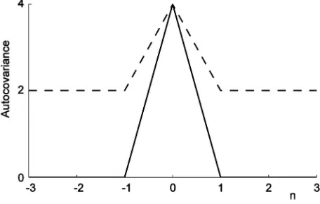
The autocovariance indicates the advantages that might be expected from ternary sequence diffusers in comparison to unipolar binary sequence diffusers. The autocovariance functions for the ternary and unipolar binary sequences are shown in Fig. 3. The binary sequence has constant out-of-phase values, but they are not zero. This leads to diffusers with a significant specular component in their polar pattern. Perfection can be achieved using a ternary sequence as the out-of-phase values are all zero.
In terms of scattering, the ternary sequence has the bet-ter reflection coefficient autospectrum because it is constant; this is shown in Fig. 4. It would be anticipated that the scat-tering from the ternary sequence would be more even with reflection angle if one repeat of the device was tested. For a periodic structure, that is, one in which many repeats of the diffuser are placed side by side but not an infinite number, this will result in all the grating lobes having the same en-ergy for the ternary sequence. For the binary sequence, on the other hand, the specular lobe will have a higher level when compared to the other lobes.1 共Note: The autospectra for MLS usually seen in the literature have a reduced Nf= 0
value, however this is for bipolar sequences.兲
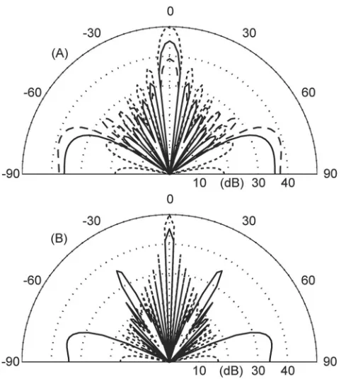
Figure 5 shows the scattering from the ternary and uni-polar binary diffusers alongside the scattering from a plane surface. A simple Fourier prediction model is used.1 d
[image:4.612.323.551.36.181.2]= 10 cm. Figure 5共a兲is at the design frequency. As expected,
FIG. 3. Autocovariance for two sequences:– – –, unipolar binary and —, ternary.
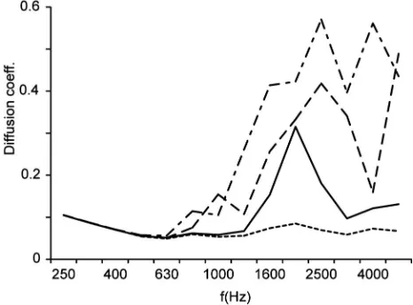
the ternary diffuser has three lobes all of the same energy, whereas the specular lobe is not so well suppressed for the unipolar binary diffuser. Figure 5共b兲shows the case one oc-tave higher. At this frequency, the last well in the ternary sequence no longer has a reflection coefficient of −1. Now the well is half a wavelength deep, and the reflection coeffi-cient is +1. In fact, the sequence of reflection coefficoeffi-cients is now the same as for the unipolar binary sequence, and hence the two diffusers have the same polar responses. Hence, the ternary diffuser provides better scattering than the unipolar binary diffuser at odd multiples of the design frequency and the same scattering at even multiples of the design frequency. This trend continues at higher frequencies as illustrated by the plot of diffusion coefficient versus frequency in Fig. 6.
The diffusion coefficient is evaluated using AES-4id-2001,8 and a higher value indicates better dispersion.
So far the performance has only been discussed at har-monics of the design frequency. Between these frequencies, the phase of the reflection coefficient offered by the well of fixed depth is neither 180° nor 0°. The waves reflected from this well will be partly out-of-phase with the waves from the parts of the diffuser with R= + 1. Consequently, the perfor-mance is improved over the unipolar binary diffuser for these in-between frequencies, a finding confirmed by Fig. 6.
V. MODULATION AND PERIODICITY
The overall performance could be improved at many frequencies by removing the repetition of the diffusers as this would remove the defined grating lobes. This could be achieved either by using much longer sequences or by modu-lating two sequences.9,10 Using one long sequence is nor-mally avoided because of manufacturing cost, and so the use of modulation is considered here.
For Schroeder diffusers, one method is to modulate a diffuser with its inverse.1Two sequences are chosen that pro-duce the same magnitude of scattering, but with opposite phase. So if the first ternary sequence is 兵1 1 0 1 0 0 − 1其, then the complementary sequence used in modulation is the inverse of this兵−1 − 1 0 − 1 0 0 1其. Given these two base dif-fusers, a pseudorandom sequence is used to determine the order these diffusers are used; this reduces repetition.
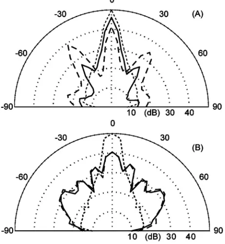
[image:5.612.322.553.33.203.2]Figure 7 shows the scattering at the design frequency for a periodic and modulated arrangement of the ternary se-quences illustrating the removal of the three lobes via modu-lation. Figure 6 shows the diffusion coefficient versus fre-quency. This shows that great improvement can be achieved but only over certain bandwidths. At even multiples of the design frequency, the two base shape reflection coefficients are identical, and so at these frequencies the structure is pe-riodic and grating lobes reduce performance. Consequently, while inverting a sequence is good for modulating Schroeder diffusers, they are not optimal here.
[image:5.612.58.287.40.184.2]FIG. 4. Autospectrum for two sequences:– – –, unipolar binary and —, ternary.
FIG. 5. The predicted scattered polar response from three surfaces: —, unipolar binary diffuser; – – –, ternary diffuser; and………, plane surface.
共a兲At the design frequency and共b兲twice the design frequency. In共b兲, the two diffuser responses are identical and overlay each other.
[image:5.612.53.294.425.693.2]Single base shape asymmetric modulation11 is where a single sequence is used, but the order of the sequence is reversed between different diffusers. For example, if the first ternary sequence is 兵1 1 0 1 0 0 − 1其, then the second se-quence used is兵−1 0 0 1 0 1 1其. An added advantage of this method is that only one base shape needs to be made. At even multiples of the design frequency, the reflection coeffi-cients all revert to 0 and 1, but the structure will not be completely periodic. However, it is found that periodicity is only partly removed, and that the grating lobes are still present because the two sets of reflection coefficient are very similar. Consequently, when choosing a sequence for asym-metrical modulation, it is necessary to find ones that are as asymmetric as possible at even multiples of the design fre-quency.
VI. BOUNDARY ELEMENT MODELING
Having established the general principles, more exacting predictions will be presented using boundary element meth-ods共BEMs兲. BEMs have been shown to give accurate results for hybrid surfaces before when compared with measurements12 and also to give accurate results for Schroeder diffusers.13Consequently, it would be anticipated that the BEM will be accurate for ternary diffusers. The model used here is a 2D BEM based on the standard Helmholtz-Kirchhoff integral equation. The open well in the ternary diffuser is modeled assuming plane-wave propaga-tion in the well, and using an element at the well entrance with the appropriate surface impedance. Previous experience13 indicates this is a reasonable model, but be-comes less accurate for oblique incidence and reflection. For the absorptive patches, the impedance was modeled using an empirical formulation14 for mineral wool with a flow resis-tivity of 50000 N m−4 and a porosity of 0.98. The scattering was predicted in the far field at discrete frequencies. The results were converted into 1 / 3 octave bands by integrating the scattered energy from nine discrete frequencies within each 1 / 3 octave band using Simpson’s rule. The source was normal to the surface.
Two diffusers were used. The first was anN= 31 unipo-lar binary diffuser based on a MLS. A little over ten periods of the device were used, the patch width was 2 cm, and the total width was 6.3 m. The second diffuser was an N= 31
ternary diffuser, with the same overall dimensions and patch size. The wells were set to be 8.5 cm deep and so the design frequency was 1 kHz.
A. Results
Figure 8共a兲shows the scattering for the 1 / 3 octave band centered on the design frequency, Fig. 8共b兲shows the scat-tering at an octave higher. The results confirm the simple analysis provided earlier. At even multiples of the design frequency, the scattering from the unipolar binary and ter-nary diffusers is similar. At odd multiples of the design fre-quency, the ternary diffuser offers more even scattering and a reduced specular lobe. It is also found that at frequencies that are not multiples of the design frequency, the ternary diffuser is better than the unipolar binary diffuser.
[image:6.612.57.287.38.158.2]FIG. 9. Predicted absorption coefficient for three surfaces: —, binary dif-fuser; – – –, ternary difdif-fuser; and………, quadriphase diffuser estimating using a BEM model.
[image:6.612.321.552.39.289.2]FIG. 7. The predicted scattered polar response from two ternary diffuser arrangements at their design frequency: —, periodic and – – –, modulated.
FIG. 8. Scattering from three diffusers predicted using a BEM model. —, binary diffuser; – – –, ternary diffuser; and………, plane surface, for the 1 / 3 octave whose center frequency is共a兲the design frequency and共b兲twice the design frequency.
[image:6.612.321.552.563.703.2]Using the BEM results, it is possible to estimate the normal incidence absorption coefficients. The results in Fig. 9 are typical for hybrid absorber-diffusers. The low-frequency response is dominated by the onset of the absorp-tion provided by the mineral wool. At high frequency the absorption coefficient is determined by the open area and is about 0.5. As the system is essentially a perforated resonant absorber, there is a peak of absorption at midfrequency. The absorption coefficient response is less smooth for the ternary diffuser. It is assumed that this is due to reflections from wells providing out-of-phase reflections when compared to other parts of the diffuser, and therefore the waves can com-bine to put energy into the reactive field. Overall, however, the absorption is similar for all diffuser types.
VII. QUADFFUSERS
A. Design
It is impossible to greatly improve the performance of the ternary diffusers at even multiples of the design fre-quency when the diffuser only has reflection coefficients of 0 and 1. To overcome this, more well depths need to be used. For only a few absorbent wells and many different depth wells, it would be possible to use index sequences.15 How-ever, this would complicate the construction of the surface, and the absorption coefficient would be relatively small. An-other solution would be to use active elements. It has been shown16 that with active impedance technologies it is pos-sible to create R= −1 across a 3–4 octave bandwidth. How-ever, this can only be achieved at low- to midfrequencies due to limitations of the active technologies, and, furthermore, active diffusers are very expensive. Another solution would be to bend and shape the diffuser so the front face was no longer flat, and therefore use corrugation to break up the specular reflection; this works well for binary amplitude diffusers.17
Another simple approach is to use one more well depth. Consequently, diffusers with four different reflection coeffi-cients will be considered. At the design frequency, these co-efficients should be R= −1, 0, +1, and. It is assumed that the last coefficient,, is generated by a rigid walled well of a certain depth, and consequently 兩兩= 1, and the well purely causes a change in the phase of the reflection. In choosing an appropriate value for, it is necessary to consider not just the design frequency f0, but also the effects at multiples of the
design frequency, because the idea behind introducing this additional wave depth is to improve performance at even multiples of the design frequency. For instance, if⬔=/ 2 at f0, then at 2f0, the reflection coefficient would be −1.
However, at 4f0, the reflection coefficient would be +1 and
so a poor performance at this frequency would be expected. Using a depth related by relatively prime fractions, e.g., 1 / 2, 1 / 3, 1 / 5, 1 / 7, etc. to the / 4 well depth, or maybe prime rationals, e.g., 1 / 2, 3 / 5, 7 / 11, etc., ensures that there are no frequencies in the audible frequency range for which all the nonabsorbing parts of the diffuser reflect in phase. Conse-quently, at the design frequency theR= −1 wells are set to a
depth of/ 4, and theR=wells are set to/ 6. This puts the frequency at which these two well types radiate in phase at 24f0.
Choosing an appropriate number sequence for this de-sign is no longer simple. While there are quadriphase se-quences in number theory, these do not normally have zero terms in them. For a 31-element diffuser, there are too many combinations to exhaustively search all combinations. Con-sequently, the approach used is to adapt the current ternary sequence. It is assumed that the same open area is required, and consequently the zeros in the sequence will be main-tained in their current locations. Then all that remains is to determine which −1’s and 1’s in the sequence need to be changed to/ 6 wells. In the original ternary sequence, there are 16 −1’s and 1’s, and consequently it is possible to search all possible combinations to find the best arrangement. The search is for the best average merit factor for the first five harmonics of the design frequency, as these are in the fre-quency range 共1 – 5 kHz兲of interest here.
B. Results
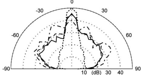
[image:7.612.320.553.35.207.2]Figure 10 shows the diffusion coefficient versus fre-quency response predicted using the BEM. The use of mul-tiple well depths in the quadriphase diffuser produces better scattering than the other diffusers except at 1 kHz, where the ternary diffuser performs better. However, this diffusion re-sponse needs to be reviewed alongside the absorption coef-ficients shown in Fig. 9. Only above⬇2 kHz is the diffusion performance of these devices important, because in the fre-quency range 1 – 2 kHz the devices are essentially just ab-sorbers, and below 1 kHz the surface has a decreasing effect on the sound wave because of insufficient absorption. At frequencies, such as 4 kHz, where the unipolar and ternary diffusers produce identical scattering, the quadriphase dif-fuser is performing better. The scattering at 4 kHz is shown in Fig. 11; the design is working as expected. The absorption coefficient共Fig. 9兲is similar to that for ternary diffusers.
VIII. HIGHER DIMENSION ARRAYS
So far this paper has been concerned with diffusers that scatter in one plane. However, there are many applications where diffusers with hemispherical reflection patterns are re-quired. To form hemispherical diffusers, two-dimensional ternary sequences 共in number theory these would be called sequence arrays兲are needed. There are a variety of methods for making multidimensional binary18 and ternary arrays.19
Consider constructing a ternary diffuser of dimensions 共in terms of number of patches兲 of N⫻M. There should be ⬇NM/ 2 zeros in the sequence for a nominal 50% absorp-tion. Whether a sequence can be constructed depends on the values of N and M. There are three standard construction methods: folding, modulation共Kronecker product in number theory兲, and periodic multiplication. Even so, there will be many array sizes that cannot be made with ideal two-dimensional autocovariance properties.
A. Folding
Schroeder20 showed that a folding technique called the Chinese Remainder Theorem could be applied to phase grat-ing diffusers based on polyphase sequences. D’Antonio4 used the same technique for a binary hybrid diffuser. Refer-ences 1 and 5 give comprehensive descriptions of the pro-cess. The folding process wraps a 1D sequence into a 2D array while preserving the autocovariance properties. This can also be applied to ternary sequences. To use this method,
N and M must be co-prime. The requirement for 50% ab-sorptive patches means a correlation identity derived ternary sequence must be used with lengthNM= 2m− 1, withmbeing odd.
The folding technique can be viewed as an indexing process. The 1D sequence, ak, will be indexed using k
= 1 , 2 , 3 , 4 , . . . ,NM. The elements of the 2D array, bp,q, are
given by bp,q=akwithp=kmodN andq=kmodM, where
共p,q兲are the coordinates of the elements in the folded array. Consider a real ternary sequence with N= 9 and M= 7:
ak=兵0 , 0 , 0 , 0 , 1 , 0 , 0 , 0 , 0 , 1 , 0 , −1 , 0 , 0 , 0 , 0 , 0 , −1 , 0 , 0 , 0 , 0 ,
1 , 0 , 0 , 0 , 0 , 0 , 0 , 0 , 0 , 1 , 0 , 0 , 0 , 0 , 0 , 0 , 0 , 0 , 1 , 1 , 1 , 0 , 1 , − 1 , 0 , 0 , 1 , 0 , −1 , 0 , 0 , 0 , 0 , 0 , 1 , −1 , 0 , 0 , −1 , 0 , 0 , −1 , 0 , 0其.
The folded 2D array is then
兵0其 0 0 1 − 1 0 0
0 0 0 1 − 1 0 0
0 0 0 0 0 0 0
0 1 0 0 0 − 1 0
1 0 − 1 0 0 0 0
0 0 1 0 1 1 1
1 0 − 1 0 0 0 0
0 1 0 0 0 − 1 0
0 0 0 0 0 0 兵0其
.
The autocovariance of this array is ideal; it is a Kronecker delta-function.
The number of sequences that can be constructed using this method with 50% absorbent patches is rather limited 共only 7⫻73, 23⫻89, 7⫻31⫻151, 217⫻151, 31⫻1057, or 7⫻4681 forNM艋216兲, and consequently other construction
methods are needed. However, the folding process will be useful again later because it will allow the resizing of other arrays.
B. Modulation
Modulation was a process that was used to allowed dif-fusers to be arranged in a nonperiodic fashion by modulating one or more base shapes with a binary sequence. Another way of viewing the outcome of this process is that it forms a single longer length sequence. A very similar process can be used to form arrays using ternary and binary sequences and arrays.
1. Ternary and binary modulation
By modulating a ternary sequence with a perfect aperi-odic binary array, a ternary array with ideal autocovariance properties can be obtained.共Note, it is important to modulate the array by the sequence and not vice versa.兲 Consider a length 7 correlation identity derived ternary sequence a
=兵1 , 1 , 0 , 1 , 0 , 0 , −1其. This is used to modulate the perfect aperiodic binary array, b:b=兵−1 −1−1 1其 to form a 2⫻14 length array,c, given by
c
=
再
− 1 − 1 − 1 − 1 0 0 − 1 − 1 0 0 0 0 1 1 − 1 1 − 1 1 0 0 − 1 1 0 0 0 0 1 − 1冎
.This array has ideal periodic autocovariance properties. As the binary array has no zeros, the modulated array has the same proportion of absorbent patches as the original ternary sequence, 40% in this case. For long sequences, the propor-tion tends toward 50%.
[image:8.612.55.289.36.159.2]An issue that is not often discussed in the number theory literature is the imbalance between the distribution of −1 and 1’s in a sequence. This is important to the diffusers because the proportion of −1 and 1’s changes the amount of attenua-tion of the specular reflecattenua-tion. In this case, the modulaattenua-tion has produced an array with a more even balance of −1 and 1’s than the original ternary sequence, and consequently it would be expected to perform better at attenuating the specu-lar reflection.
FIG. 11. Predicted scattering for three diffusers and a plane surface at four times the design frequency: —, unipolar binary diffuser; – – – , ternary diffuser; –·–·, quadriphase diffuser; and………, plane surface.
There is only one known perfect aperiodic binary se-quence, the one shown above. Consequently, 2⫻14, 2⫻62, 2⫻254, 14⫻146, 46⫻178, and 2⫻16382 are the array sizes that can be constructed by this method with ⬇50% efficiency forNM艋216; again the allowable array sizes are rather few. Furthermore, as the resulting array sizes haveN
and M, which are not co-prime, it is not possible to refold these arrays to get other sizes.
2. Ternary and ternary modulation
The efficiency共proportion of zeros兲of the derived array by modulation is a product of the efficiency of the original array and sequence. Consequently, it is possible to modulate a ternary array by a ternary sequence, provided the product of their efficiencies is about 50%. Two aperiodic perfect ter-nary arrays with 67% zeros are
d1=
再
1 0 1
1 0 − 1
冎
, d2=冦
1 1
0 0
1 − 1
冧
. 共3兲
Consequently, if either of these is combined with a perfect periodic ternary sequence with 75% zeros, the overall design goal of an array with 50% zeros is achieved.
In this case, the correlation identity derived ternary se-quences are not useful because they have too low an effi-ciency. On the other hand, some Ipatov ternary sequences and those based on the Singer difference sets are appropriate.21,22 If the efficiency goal is set to be between 45% and 55%, then there are four Ipatov ternary sequences that can be used of length 13, 121, 31, and 781. While these achieve an efficiency of about 50%, respectively, there is an imbalance between the number of +1 and −1 in the se-quence, leading to somewhat less than optimal specular re-flection absorption, so these are not considered further.
By combining two binary sequences based on Singer difference sets, it is possible to form a ternary sequence with the desired efficiency and a better balance of −1’s and 1’s. Difference sets are used to form sequences with the best possible autocovariance. The Singer difference set is a par-ticular class of difference sets, and has the following param-eters:
共N,k,␥兲=
冉
q2r+1− 1
q− 1 ,
q2r− 1
q− 1 ,
q2r−1− 1
q− 1
冊
, 共4兲whereNis the length of the sequence,kthe number of 1’s in the two binary sequences formed, and␥ the maximum out-of-phase autocovariance of the two binary sequences.qandr
are constants and are specified below. The efficiency of the ternary sequence formed by combining the binary sequences is approximately given by共q− 1兲/q. Since the requirement is to find a sequence with 75% efficiency, q= 4 is used. This meets a necessary requirement thatq= 2s, wheresis an inte-ger.
The possible sequences areN= 21, 341, 5461, . . ., which are the cases forr= 1, 2, and 3. Consider the case ofN= 21, for example. The two Singer difference sets for this case are
D1 =兵3 , 6 , 7 , 12, 14其 and D2 =兵7 , 9 , 14, 15, 18其, where the numbers in the brackets indicate the locations of the 1’s in
the sequence. The unipolar binary sequence for D1 is a
=兵0 , 0 , 1 , 0 , 0 , 1 , 1 , 0 , 0 , 0 , 0 , 1 , 0 , 1 , 0 , 0 , 0 , 0 , 0 , 0 , 0其and for
D2 isb=兵0 , 0 , 0 , 0 , 0 , 0 , 1 , 0 , 1 , 0 , 0 , 0 , 0 , 1 , 1 , 0 , 0 , 1 , 0 , 0 , 0其. To form the ternary sequence, the cross-correlation
be-tween these two sequences is found: sab
=兵2 , 0 , 0 , 1 , 0 , 2 , 1 , 1 , 0 , 2 , 2 , 0 , 1 , 2 , 1 , 2 , 0 , 2 , 2 , 2 , 2其. The fi-nal sequence,c, is then given by
c=q1−r
冉
sab−q2r−1− 1
q− 1
冊
, 共5兲which in this case yields c=兵1 , −1 , −1 , 0 , −1 , 1 , 0 , 0 , −1 , 1 , 1 , −1 , 0 , 1 , 0 , 1 , −1 , 1 , 1 , 1 , 1其. This sequence has ideal autocovariance properties.
Having obtained the necessary ternary sequence, it is now possible to form the array. The sequencecis modulated with the first perfect aperiodic ternary arrayd1shown in Eq.
共3兲to form an array that has size 63⫻2 and has ideal auto-covariance properties with a maximum value of 64. Hence, the absorption coefficient at high frequency in this case is nominally 0.51. The array has 28 values at −1 and 36 values at +1, and so there is good attenuation of the specular reflec-tion at odd multiples of the design frequency.
Array sizes that are square will be more useful, because if the 63⫻2 diffuser is used periodically, the small repeat distance in one direction will reduce performance. By apply-ing the Chinese Remainder Theorem in reverse, it is possible to unfold this array into a 126⫻1 sequence, and then refold it into two other array sizes 18⫻7 and 14⫻9, which are squarer.
3. Periodic multiplication
The final design process is to use periodic multiplica-tion. Two arrays can be multiplied together to form a larger array. Consider array 1 to bebp,qof sizeNb⫻Mb, which has
an efficiency of Eb, and array 2 to be cp,q of size Nc⫻Mc,
which has an efficiency ofEc. Then the new array is a
prod-uct of the periodically arranged arrays, bp,q·cp,q of size NbNc⫻MbMc, and the efficiency will beEbEc. A necessary
condition is thatNbandNcare co-prime, and so areMband Mc, otherwise the repeat distance for the final arrays will be
the least common multiples ofNbandNcin one direction and MbandMcin the other.
For example, the ternary sequence derived previously from Singer difference sets, c, can be folded into an array that is 7⫻3,
兵1, 0, 1
0, 1, 0
−1, 1, −1
−1, 1, −1
1, 0, 1
−1, 1, −1
1, 0, 1其,
which has an efficiency of 76%. This can then be multiplied by the ternary array d2, which has an efficiency of 67% to
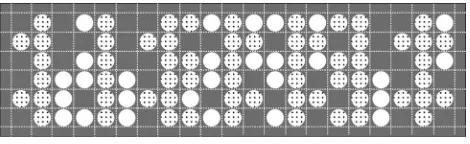
the number of −1 and 1’s with 28 and 36, respectively, of each. Figure 12 shows a visualization of a mask for this sequence.
This multiplication process can involve a binary array multiplied by a ternary array, or two ternary arrays multiplied together. Except for the perfect 2⫻2 binary array, perfect binary arrays will have an imbalance between the number of +1 and −1 terms, which could lead to an imbalance in the final array design and insufficient attenuation of the specular reflection lobe. In general, perfect binary arrays of size N
⫻M have NM mod 4 = 0 andNM=共2k兲2, wherek is an
in-teger, and they have an imbalance of冑NM.
C. Array discussions
Once the array is formed, any periodic section can be chosen and many other manipulations can be done and still preserve the good autocovariance. Procedures that can be done on their own or in combination include the following.
共i兲Using a cyclic shift to move the pattern around.cp,q
=bp+u,q+v, whereuandvare integers and the indexesp+uan q+vare taken modulo NandM, respectively.
共ii兲Mirror image the array cp,q=b±p,±q.
共iii兲Invert the sequencecp,q= −bp,q.
共iv兲Rotation by 90°cp,q=bq,p.
共v兲 Under sample the array, cp,q=bup,vq, provided both u,Nandv,M are co-prime.
These will not change the acoustic performance, but may change the visual aesthetic. It can also help to make the array more asymmetric, which can be useful in modulation. The main problem in forming these arrays is that there is only a limited set of arrays, which provide ideal autocovari-ance properties, the required efficiency to give the desired absorption coefficient, and a reasonable balance between the number of −1’s and 1’s in the sequence leading to good suppression of the specular lobe. In work on binary sequences,23it has been shown that relaxing the requirement for ideal autocovariance enables more different length se-quences to be formed. This should also be possible for the ternary sequence case. For example, where there are a large number of elements in a sequence, it may be possible to truncate the sequence, losing one or two elements, and still gain good 共but not ideal兲 autocovariance properties. This type of truncation might then give the right sequence length for folding into an array with the desired size.
IX. CONCLUSIONS
The performance of a new sort of room acoustic diffuser that is based on ternary sequences has been discussed. The
rationale and performance of these have been analyzed using simple prediction models and concepts, as well as more ac-curate boundary element models. By adding wells to hybrid diffuser surfaces, thus forming ternary diffusers, a useful im-provement in performance is achieved for a modest depth penalty. While this produces an improved performance for odd multiples of the design frequency, at even multiples the performance of the ternary structures is the same as for the hybrid diffuser surfaces made from unipolar binary se-quences. Using two different well depths reduces this prob-lem and allows more broadband improvements in scattering. A method for obtaining the design sequence for these four-level 共quadriphase兲 diffusers is discussed. Design methods for transforming the sequences into arrays and thus produc-ing hemispherical diffusers have been outlined. While there are a number of methods available for construction, the num-ber of different arrays available with ideal autocovariance properties is rather small. Future work will undertake mea-surements to confirm the performance of the surfaces, and examining methods of construction so the surfaces can be easily and cheaply made.
1T. J. Cox and P. D’Antonio,Acoustic Absorbers and Diffusers: Theory,
Design and Application共Spon Press, 2004兲.
2M. R. Schroeder, “Diffuse sound reflection by maximum-length
se-quences,” J. Acoust. Soc. Am. 57, 149–150共1975兲.
3J. A. S. Angus, “Sound diffusers using reactive absorption grating,”
Pro-ceedings of the 98th Convention of the Audio Engineering Society, paper no. 3953共1995兲.
4P. D’Antonio, “Planar binary amplitude diffusor,” U.S. Pat. No. 5,817,992
共1998兲.
5J. A. S. Angus and P. D’Antonio, “Two dimensional binary amplitude
diffusers,” Proceedings of the Audio Engineering Society, paper no. 5061
共D-5兲 共1999兲.
6P. Fan and M. Darnell,Sequence Design for Communication Applications
共John Wiley and Sons, Inc., 1996兲.
7P. Fan and M. Darnell,Sequence Design for Communication Applications
共John Wiley and Sons, Inc., 1996兲, pp. 180–183.
8AES-4id-2001, “AES Information document for room acoustics and sound
reinforcement systems—Characterisation and measurement of surface scattering uniformity,” J. Audio Eng. Soc. 49, 149–165共2001兲.
9J. A. S. Angus, “Using grating modulation to achieve wideband large area
diffusers,” Appl. Acoust. 60, 143–165共2000兲.
10J. A. S. Angus and C. I. McManmon, “Orthogonal sequence modulated
phase reflection gratings for wide-band diffusion,” J. Audio Eng. Soc. 46, 1109–1118共1998兲.
11P. D’Antonio and T. J. Cox, “Aperiodic tiling of diffusers using a single
asymmetric base shape,” Proceedings of the 18th ICA, paper Mo2.B2.3
共2004兲.
12L. Xiao, T. J. Cox, and M. R. Avis, “Active diffusers: Some prototypes
and 2D measurements,” J. Sound Vib. 285, 321–339共2005兲.
13T. J. Cox and Y. W. Lam, “Prediction and evaluation of the scattering from
quadratic residue diffusers,” J. Acoust. Soc. Am. 95, 297–305共1994兲.
14M. E. Delaney and E. N. Bazley, “Acoustical properties of fibrous
absor-bent materials,” Appl. Acoust. 3, 105–116共1970兲.
15M. R. Schroeder, “Phase gratings with suppressed specular reflections,”
Acustica 81, 364–369共1995兲.
16L. Xiao, T. J. Cox, and M. R. Avis, “Maximum length sequence and
Bessel diffusers using active technologies,” J. Sound Vib. 289, 807–829
共2006兲.
17T. J. Cox and P. D’Antonio, “Optimized planar and curved diffsorbors,”
Proceedings of the 107th Convention of the Audio Engineering Society, paper no. 5062, New York共1999兲.
18T. J. Cox and P. D’Antonio, “Optimized planar and curved diffsorbors,”
Proceedings of the 107th Convention of the Audio Engineering Society, paper no. 5062, New York共1999兲, pp. 297–310.
19M. F. M. Antweiler, L. Bomer, and H. D. Luke, “Perfect ternary arrays,”
IEEE Trans. Inf. Theory 36, 696–705共1990兲.
[image:10.612.57.292.32.104.2]20M. R. Schroeder,Number theory in science and communication: With
FIG. 12. A visualization of a 21⫻6 ternary array mask. The white holes open up to nonabsorbing wells共R= −1兲, the shaded holes open up to mineral wool共R= 0兲, and the rest of the mask is reflecting共R= 1兲.
applications in cryptography, physics, digital information, computing, and self-similarity共Springer, 1997兲.
21M. R. Schroeder,Number theory in science and communication: With
applications in cryptography, physics, digital information, computing, and self-similarity共Springer, 1997兲, pp. 178–183.
22V. P. Ipatov, “Ternary sequences with ideal autocorrelation properties,”
Radio Eng. Electron. Phys. 24, 75–79共1979兲.
23H. D. Luke, H. D. Schotten, and H. Hadinejad-Mahram, “Binary and