Effects of Cutting Conditions on the Work Damaged
Layer Formed during Cutting Heat-resistant Alloy
(12%Cr Steel)
Masu Yamada
1, Keiji Sonoya
2,*, Yuki Watanabe
21Department of Technical Development, TBM Corporation, Japan 2Department of Mechanical Engineering, University of Yamanashi, Japan
Copyright © 2015 by authors, all rights reserved. Authors agree that this article remains permanently open access under the terms of the Creative Commons Attribution License 4.0 International License
Abstract
The effect of cutting conditions such as numbers of tool teeth, depth of cut and cutting speed on the cutting resistance about 12%Cr steel hasn’t been studied before. So the effect of cutting conditions on the cutting resistance will be investigated in this paper. The relationship between cutting resistance and work damaged layer will be taken into consideration. The results are as follows. (1)The cutting resistance becomes larger with the increase of the depth of cut and the numbers of tool teeth. It has no relation with cutting speed. (2)The depth of work damaged layer increase with the increase of the depth of cut and numbers of tool teeth. It does not change with the increase of cutting speed. (3)The deformation of cutting surface becomes larger with the increasing depth and numbers of tool teeth. It changes a little with the increase of cutting speed. (4)It was found that the depth of work damaged layer increased with the increase of the cutting resistance. The depth of work damaged layer is thought to have an intimate relation with the cutting resistance. (5)The experimental value for work damaged layer by hardness measuring is thought to be reasonable value, because the experimental value is nearly equal to the evaluated one obtained from Sokolovskii’s stress equation.Keywords
12%Cr Steel, Numbers of Tool Teeth, Dept of Cut, Cutting Speed, Cutting Resistance, Work Damaged Layer1. Introduction
Recently, turbines have been frequently used in the engines of aircrafts and thermal power plants, in particular, high gas temperature at the outlet is required to improve the efficiency of gas turbines, and difficult-to-cut heat-resistant alloy steels with a high melting point have been frequently used for turbine blades. In addition, high efficiency has also
been demanded for steam turbines, promoting the use of large turbine blades and thin blades. High precision is required in the processing of any type of blade.
The methods for processing blades have been changed. The blade material has changed from shaped steel to forged steel. In the 1980s, forged steel was intensively applied to blades in Japan in conjunction with the improvement in the performance of forging systems. In addition, the method of forging is gradually changed first from free forging to die forging and then to precision forging[1]. Under these circumstances, the deformation of forged materials during machining has been a significant problem to be solved in terms of processing accuracy.
Upon cutting, a work-damaged layer with altered material qualities is formed at the surface of the cut material[2][3] [4]. The causes are considered to be the mechanical energy generated by cutting force, thermal energy due to temperature increase, and a combination of these two.
Because residual strain is induced in these work-damaged layers, residual stress is generated and stored in the form of potential energy, causing the deformation of the layers[5]. The energy level of the work-damaged layers is higher than that of the base metal. The properties of work-damaged layers are expected to depend on the materials to be cut and the cutting conditions. There are reports[6][7] [8] on the relationship between cutting conditions and the properties of work-damaged layers of nonferrous materials and soft iron; however, the number of reports on this relationship for heat-resistant materials such as 12%Cr steel are limited.
2. Experiment
2.1. Materials
12%Cr ferrite steel, a rolled steel actually used for turbine blades, was used in the experiment. Nb, V, Mo, and W were added to the 12%Cr steel to improve the creep rupture strength. Table 1 summarizes the chemical composition. The dimensions of the plate specimen are 200 (length) × 50 (width) × 10 (thickness) mm. The length of the plate specimen is in the direction of rolling. The finished surface roughness of the cut surface is Ra = 1.2 μm. X-, Y-, and Z-directions refer to the directions of length, width, and thickness, respectively. The plate specimen was annealed for 1 h at 675℃ before cutting
2.2. Cutting and Measurement Methods
A machining center (VU50A, Mitsui Seiki Kogyo Co., Ltd.) was used for cutting. Cutting conditions summarized in Table 2 were used for all plate specimens. During cutting, a cutting fluid was used to suppress the increase in temperature of plate specimens as much as possible. A shoulder cutter with 8 cutting edges (Seco Tools) was used as the cutting tool.
Table 1. Chemical compositions of 12Cr steel Chemical Compositions (wt %)
C Si Mn P S Ni Cr Mo
0.17 0.35 0.70 0.017 0.001 0.53 10.46 0.87
V W Al Co Sn N Ti Nb
[image:2.595.315.547.442.631.2]0.22 0.01 0.01 0.01 0.01 0.06 0.01 0.40
Table 2. Cutting conditions
Cutting speed 60,120,180,240 m/min
Depth of cut 0.25,0.5,0,75,1.0mm
Cutting feed rate 480 mm/min
Feed/tooth 0.1 mm
Numbers of cutting teeth 1, 4, 8
Rake angle 16 deg.
Note: The cutting lubricant was used
Cutting conditions, such as the depth of cut, the number of cutting teeth, and cutting speed, were changed in the cutting experiments. The depths of cut were 0.25, 0.5, 0.75, and 1.0 mm. The numbers of cutting teeth were 1, 4, and 8. The cutting speeds were 60, 120, 180, and 240 m/min.
The cutting resistances in the three directions (X-, Y-, and Z-directions) were measured using a fixed dynamometer (9257B, Kistler Group) under various combinations of the above conditions. The mean of 2,000 cutting resistances measured using the dynamometer in 1 s was used as the cutting resistance. The plate specimen was fixed using jigs placed on the top plate of the dynamometer.
The amount of deformation was measured by using a
coordinate-measuring machine (XYZAX G800D, Tokyo Seimitsu Co., Ltd.). The amount of deformations at a total of 50 points [10 points (in the X-direction with an interval of 20 mm and 10 mm margins on both sides) × 5 points (in the Y-direction with an interval of 10 mm and 5 mm margins on both sides)] was measured.
The cross section in the vicinity of the cut surface was observed microscopically at the center of the plate specimen, and Vickers hardness (load, 0.1 N) of the plate specimen was measured in the Z-direction at intervals of 10 μm from the cut surface to determine the depth of the work damaged layer.
Japanese Industrial Standards (JIS)-14 plate specimens were prepared from 12%Cr-steel based metal and annealed. Thus-treated specimens were used in the tensile test with a hydraulic universal testing machine (Autograph AG-IS, 100 kN, Shimadzu Corporation) to obtain the modulus of strain hardening of 12%Cr steel from stress–strain curves.
3. Results
3.1. Microstructure in the Vicinity of Cut Surface
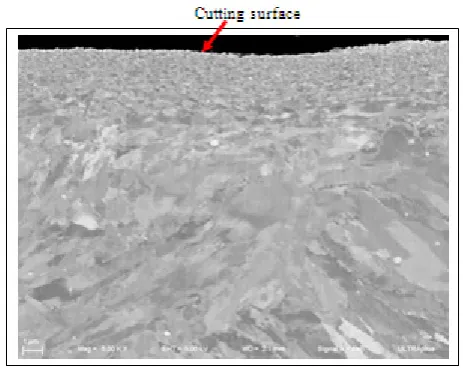
Figure 1 shows an example of the SIM microstructure in the vicinity of the cut surface of a plate specimen obtained after cutting. There are refined crystals of 2μm level thickness, and some plastic flow follows these.
3.2. Effects of Cutting Conditions on Cutting Resistance
Etching: Picric acid
Cutting speed:120m/min, Depth of cut:0.25mm, Numbers of cutting teeth:8
Figure 2. Micro structure of cross-section on the vicinity of cutting surface of 12Cr steel
half those in the X- and Z-directions. This is because the effect of cutting on the cutting resistance in the Y-direction is considered to be small owing to the diameter of the cutter (63 mm) being larger than the width of the plate specimen (50 mm).
Figure 3. Relation between cutting resistance and number of teeth
Figure 3 shows the relationship between cutting resistance and number of cutting teeth (1–8) at a constant cutting speed of 120 m/min and a constant depth of cut of 1.0 mm. The cutting resistance differs greatly depending on the number of cutting teeth; the cutting resistance in all directions significantly increases with increasing number of cutting teeth. The effect of the number of cutting teeth on cutting resistance was found to be significant.
Figure 4. Relation between cutting resistance and cutting speed
Figure 4 shows the relationship between cutting resistance and cutting speed (60–240 mm/min) at a constant depth of cut of 1.0 mm and a constant number of cutting teeth of 8. With increasing cutting speed, the cutting resistance in the X-direction slightly decreases; however, those in the Y- and Z-directions tend to slightly increase.
3.3. Effect of Cutting Conditions on Depth of Work Damaged Layer
As shown in Fig. 1, no plastic flow, which generally occurs during cutting, was observed in the microstructure of 12%Cr steel[5]. Figure 5 shows an example of the relationship between Vickers hardness in the Z-direction and the distance from the cut surface at the cutting speed of 120 m/min, the number of cutting teeth of 8, and the depth
of cut of 0.75 mm. A large variation in Vickers hardness is observed at the surface layer, which is considered to correspond to the work damaged layer. Therefore, the depth at which a large variation in Vickers hardness is no longer observed (the first depth at which the same Vickers hardness is consecutively obtained five times) in the Z-direction is defined as the depth of the work damaged layer.
[image:3.595.316.550.377.520.2]Cutting speed: 120m/min, Dept of cut: 0.75mm, Number of teeth: 8
[image:3.595.64.295.413.538.2]Figure 5. Relation between Vickers hardness and distance from cutting surface
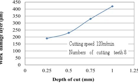
Figure 6. Relation between work damage layer and depth of cut
Figure 6 shows the relationship between the depth of the work damaged layer and the depth of cut (0.25, 0.5, 0.75, and 1.0 mm) at a constant cutting speed of 120 m/min and a constant number of cutting teeth of 8. The depths of the work damaged layer for the depths of cut of 0.25 and 0.5 mm are similar, 190 and 230 μm, respectively; however, with further increasing depth of cut, the depth of the work damaged layer markedly increases to reach 420 μm at a depth of cut of 1 mm.
Figure 7 shows the relationship between the depth of the work damaged layer and the number of cutting teeth (1–8) at a constant cutting speed of 120 m/min and a constant depth of cut of 1 mm. The depth of the work damaged layer for one cutting tooth is 230 μm; with increasing number of cutting teeth, the depth of the work damaged layer linearly increases and reaches 430 μm when the number of cutting teeth is 8.
0
100
200
300
400
500
600
700
0 2 4 6 8 10
C
utti
ng r
es
istanc
e
[N
]
Numbers of teeth
x axis y axis z axis0 100 200 300 400 500 600 700 800 900
0 60 120 180 240 300
C
uttin
g r
es
is
ta
nc
e[N
]
Cutting speed[mm/min] x axis y axis z axis
Depth of cut: 1mm Numbers of teeth: 8
Base metal
Work damage layer
0 50 100 150 200 250 300 350 400 450
0 0.25 0.5 0.75 1 1.25
W
or
k
d
am
age
laye
r (
μm
)
Figure 7. Relation between work damage layer and number of cutting teeth
Figure 8. Relation between work damage layer and cutting speed
Figure 8 shows the relationship between the depth of the work-damaged layer and cutting speed (60–240 m/min) at a constant depth of cut of 1 mm and a constant number of cutting teeth of 8. The depth of the work damaged layer slightly increases from 360 to 430 μm with increasing cutting speed from 60 to 120 m/min; however, a negligible increase in the depth of the work damaged layer is observed with a further increase in cutting speed.
3.4. Effect of Cutting Conditions on Amount of Deformation
[image:4.595.82.544.82.249.2]Figure 9. The deformation amount of test plate after cutting
Figure 9 shows the amount of deformation for different depths of cut (0.25, 0.5, 0.75, and 1.0 mm) at a constant cutting speed of 120 m/min and a constant number of cutting teeth of 8. The amount of deformation is ~0.14 mm at a depth of cut of 0.25 mm. The amount of deformation tends to increase with increasing depth of cut.
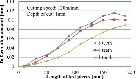
Figure 10. The deformation amount of test plate after cutting
Figure 10 shows the amount of deformation for different numbers of cutting teeth (1–8) at a constant cutting speed of 120 m/min and a constant depth of cut of 1 mm. The amount of deformation is 0.09 mm when the number of cutting teeth is one. The amount of deformation increases with increasing number of cutting teeth. The amount of deformation is 0.125 mm when the number of cutting teeth is 8.
0 50 100 150 200 250 300 350 400 450 500
0 1 2 3 4 5 6 7 8 9
W
ork
d
ama
ge
la
yer[
μm]
Numbers of cutting teeth
Cutting speed: 120m/min Depth of cut: 1mm
0 50 100 150 200 250 300 350 400 450 500
0 60 120 180 240 300 360
W
ork
d
ama
ge
la
yer[
μm]
Cutting speed[m/min] Depth of cut: 1mm Numbers of teeth: 8
0 0.05 0.1 0.15 0.2 0.25 0.3
0 50 100 150 200 250
D
ef
orma
tio
n
amo
un
t [
mm]
Length of test pieces [mm]
1mm 0.75m m Cutting speed: 120m/min
Numbers of cutting teeth: 8
0 0.02 0.04 0.06 0.08 0.1 0.12 0.14
0 50 100 150 200
D
ef
orma
tio
n
amo
un
t [
mm]
Length of test pieces (mm) 8 teeth 4 teeth 1 tooth Cutting speed: 120m/min
[image:4.595.60.296.270.426.2] [image:4.595.316.551.350.486.2]Figure 11. The deformation amount of test plate after cutting
Figure 11 shows the amount of deformation for different cutting speeds (60–240 m/min) at a constant depth of cut of 1 mm and a constant number of cutting teeth of 8. The amount of deformation is ~0.03 mm at maximum even when the cutting speed increases from 60 to 120 m/min; the amount of deformation changes negligibly with cutting speed.
4. Discussion
4.1. Relationship between Cutting Resistance and Depth of Work Damaged Layer
[image:5.595.62.294.80.224.2]The work damaged layer formed during cutting is considered to affect the deformation[10]. The depth of the work damaged layer can be determined by measuring the Vickers hardness in the experiment. Although the Vickers hardness changes in the work damaged layer, the depth at which the Vickers hardness remains unchanged is defined as the depth of the work-damaged layer.
Figure 12. Relation between cutting resistance and work damage layer of test plate after cutting
It is considered that the work damaged layer formed during cutting is affected by cutting resistance. The relationship between the depth of the work damaged layer and the cutting resistance when the depth of cut is changed in four steps from 0.25 to 1.0 mm is summarized in Fig. 12 on the basis of the results in Figs. 2 and 6. The depth of the
work damaged layer tends to increase with increasing cutting resistance in the X-, Y-, and Z-directions. The relationship between the depth of the work damaged layer and cutting resistance in the X-direction is similar to that in the Z-direction. Moreover, this relationship under different cutting conditions is considered unambiguous.
4.2. Comparative Evaluation of Calculated and Experimental Depths of Work Damaged Layer
Figure 13. Stress-strain curve of 12Cr steel base metal
As described above, the Vickers hardness varies in the work damaged layer, and the depth at which the Vickers hardness remains unchanged is defined as the depth of the work damaged layer. The depth of the work damaged layer is obtained experimentally by measuring the Vickers hardness. To verify the result, the depth of the work-damaged layer is also calculated using Sokolovskii’s stress equation[11].
Figure 14. Stress-strain logarithmic line of 12Cr steel base metal
Tensile tests were carried out twice because the modulus of strain hardening (μ) of the 12%Cr steel based metal is required to calculate the depth of the work damaged layer. Figure 13 shows stress–strain curves of the 12%Cr steel based metal. The stress (σ)–strain (ε) double logarithmic lines (σ = Kεμ, where K is a constant) of the 12%Cr steel based metal are linear in the plastic region, as shown in Fig. 14. From the slope of the lines, mean μ is obtained as 0.61. -0.03
-0.01 0.01 0.03 0.05 0.07 0.09 0.11 0.13 0.15
0 50 100 150 200
D
ef
orma
tio
n
amo
un
t [
mm]
Length of test pieces [mm] v60m/min v120m/min v180m/min v240m/min Depth of cut: 1mm
Numbers of cutting teeth: 8
0 50 100 150 200 250 300 350 400 450
0 200 400 600 800
W
or
k
dam
age
laye
r
[μ
m
]
Cutting resistance [N] x axis y axis z axis Cutting speed: 120m/min
Numbers of cutting teeth: 8
TP No.1
TP No.2
TP No.1: Tensile stress 984MPa TP No.2: Tensile stress 985MPa
St
ress
(M
Pa
)
Strain
y = 0.6312x + 3.6402
2.7 2.75 2.8 2.85 2.9 2.95 3 3.05
-1.5 -1 -0.5 0
logσ
logε
[image:5.595.316.548.170.371.2] [image:5.595.312.549.503.640.2] [image:5.595.58.300.512.653.2]Assuming that the force of a tooth tip is concentrated at the surface of a semi-infinite body, Sokolovskii’s stress equation is expressed as
𝜎𝜎𝑟𝑟= 𝜅𝜅2𝛼𝛼𝛼𝛼𝜁𝜁(𝜃𝜃)𝑟𝑟 , 𝜅𝜅 = ±1 (1) where σr is the radial stress and R is the concentrated stress. Because μ > 1/2, ζ(θ) is given by
𝜁𝜁(𝜃𝜃)= �cos (𝑚𝑚𝜃𝜃+𝛿𝛿)𝑐𝑐𝑐𝑐𝑐𝑐𝛿𝛿 � 𝜇𝜇
, 𝑚𝑚2=2𝜇𝜇−1
𝜇𝜇2 (2)
Here, α is a constant determined to satisfy the following conditional equation of balance:
Vertical component of RV, RV= − ∫ 𝜎𝜎𝑟𝑟𝑐𝑐𝑐𝑐𝑐𝑐𝑐𝑐𝑐𝑐𝑐𝑐
𝜋𝜋 2
−𝜋𝜋2 (3) δ is a constant determined by the angle between the teeth and the cut surface. Assuming that only force vertical to the surface is applied, R is equal to the cutting resistance in the Z-direction. From eqs. (1)–(3), r that satisfies σr ≥ σ0 (0.2% proof stress) is given by
r ≤12𝜎𝜎𝑅𝑅
0 (4)
The stress–strain curves in Fig. 13 indicate the 0.2% proof stress to be 500 MPa.
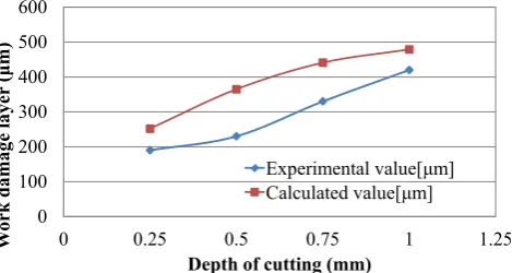
[image:6.595.62.297.570.695.2]The maximum value calculated using eq. (4) is the depth of the work damaged layer. The depths of the work-damaged layer are calculated to be 0.25, 0.37, 0.44, and 0.48 mm for the depths of cut of 0.25, 0.5, 0.75, and 1.0 mm, respectively. Figure 15 shows the calculated and experimental depths of the work damaged layer. The calculated depth of the work damaged layer is slightly higher than the experimental value for all depths of cut; however, they are similar. The depths of the work damaged layer obtained by measuring the Vickers hardness are considered to be reasonable values. The reason for the slightly larger calculated depths of the work damaged layer than the experimental values is that the force of the tooth tip is assumed to be concentrated at a slightly higher position than the cut surface, and this height is included in the calculation[12].
Figure 15. Calculated value and experimental value about work damage layer of 12 Cr steel
5. Conclusions
The effects of cutting conditions, such as the number of cutting teeth, depth of cut, and cutting speed, on cutting resistance were examined by focusing on the cutting resistance of 12%Cr steel. The relationship between the cutting resistance and the depth of the work damaged layer was examined and the following conclusions were obtained. (1) Effect of cutting conditions on cutting resistance
With the increasing depth of cut, cutting resistance tends to increase. The cutting resistance greatly differs from different numbers of cutting teeth; it significantly increases with the increasing number of cutting teeth. However, the cutting resistance changes negligibly with the increasing cutting speed.
(2) Effect of cutting conditions on depth of work damaged layer
The depth at which the Vickers hardness remains essentially unchanged in the Z-direction is defined as the depth of the work damaged layer. With the increasing depth of cut, the depth of the work damaged layer tends to increase. With the increasing number of teeth, the depth of the work damaged layer increases linearly. However, the depth of the work damaged layer changes negligibly with the increasing cutting speed.
(3) Effect of cutting conditions on amount of deformation With the increasing depth of cut or number of teeth, the amount of deformation of the cut surface tends to increase. However, the amount of deformation changes negligibly with the increasing cutting speed.
(4) Relationship between cutting resistance and depth of work damaged layer
With the increasing cutting resistance in the X-, Y-, and Z-directions, the depth of the work damaged layer tends to increase. The relationship between the depth of the work damaged layer and the cutting resistance in the X-direction is very similar to that in the Z-direction. Moreover, this relationship under different cutting conditions is considered unambiguous.
(5) Comparative evaluation of calculated and experimental depths of work damaged layer
The depths of the work damaged layer calculated using Sokolovskii’s stress equation and obtained experimentally are similar. Therefore, the depths of the work damaged layer obtained by measuring the Vickers hardness are considered to be reasonable values. The reason for the slightly larger calculated depths of the work damaged layer than the experimental values is that the force of the tooth tip is assumed to be concentrated at a slightly higher position than the cut surface, and this height is included in the calculation.
0 100 200 300 400 500 600
0 0.25 0.5 0.75 1 1.25
W
or
k
dam
age
laye
r
(μ
m
)
Depth of cutting (mm)
REFERENCES
[1] Kosakata, H., Ishikawa, K., Ono, S., Morishita, H. and Ando, H., Precision Forging, Nikkan Kogyo Shinbun,(2010,October),p.6 (in Japanese).
[2] Taniguchi, M., Study on damaged surface layer in hot machining (2nd Report), The research report of engineering department of Yamaguchi University, Vol.27,No.2 (1977),pp263-267 (in Japanese).
[3] Hikiji, R., Aburada, K., Harada, M., Ueno, T.and Yoshimitsu, S., Effect of material characteristics on work hardened surface layer in metal cutting, the research report of Kagoshima National College of Technology, Vol.34 (1999),pp.5-9 (in Japanese).
[4] Yuhta ,T., Tagashita, K., Obsevation on the Cold worked region produced by the orthogonal cutting, Journal of the Society for Precision Engineering, Vol.39,No.3 (1973),pp.312-217 (in Japanese).
[5] Sasahara, H., Obikawa, T. and Shirakashi, T., Change of mechanical characteristics in machined layer with machining sequence, Journal of the Society for Precision Engineering, Vol.61,No.10 (1995),pp.1453-1457 (in Japanese).
[6] Shirakashi, T., Obikawa, T., Sasahara, H. and Wada, T., The analytical prediction of the characteristics within machined surface layer (1st Report), Journal of the Society of
Mechanical Engineerings, Vol.59,No.10 (1993),pp.1695-1700 (in Japanese).
[7] Shirakashi, T., Obikawa, T., Sasahara, H. and Wada, T., Effect of tool condition on residual stress distribution within machined sublayer (2nd Report), Journal of the Society of Mechanical Engineerings, Vol.59,No.12 (1993),pp.2003-2008 (in Japanese).
[8] Shirakashi, T., Obikawa, T., Sasahara, H. and Wada, T., Effect of tool condition on residual stress distribution within machined sublayer (3rd Report), Journal of the Society of Mechanical Engineerings, Vol.60,No.12 (1994),pp.1801-1805 (in Japanese).
[9] Okushima, K. and Kakino.Y., Study on the formation of cutting surface, Journal of the Society of Mechanical Engineerings, Vol.34,No.261 (1968),pp.971-978 (in Japanese).
[10]Hikiji, R., Aburada, K., Harada, M., Ueno, T. and Yoshimitsu, S., Effect of cutting resistance on work hardened surface layer in metal cutting, the research report of Kagoshima National College of Technology, Vol.35 (2000),pp.9-15 (in Japanese).
[11]Sokolovskii, B.B.,( Oiso translations), Theory of plasticity, Asakura Shoten, (1959),p.264 (in Japanese).