International Journal of Emerging Technology and Advanced Engineering
Website: www.ijetae.com (ISSN 2250-2459,ISO 9001:2008 Certified Journal, Volume 3, Issue 5, May 2013)603
A Study on the Effect of External Heating of the Friction Welded
Joint
Ruma
1, Mohd Abdul Wahed
2, Mohammed farhan
3 1,2,3Asst Prof, MED, NSAKCET, 500024Abstract- Friction welding is a metal joining process in which heat required is obtained by the action between the ends to be joined .in the present work an attempt has been made to study the behavior of the friction –welding joined with and without using eternal sources of heating. In the first stage of project specimen where prepared by friction welding at different speeds and tested for tensile and shear stress the result was that the specimen prepared at higher speed showed greater strength compare to specimen at lower speed .hardness at the joint is also tested at different speed and there was no appreciable change in hardness with change in welding parameters. In the second stage of project, an eternal sources of heating was used during friction welding and the specimen were prepared at low speed in order to reduce the power at higher speeds and time consumed for welding .
When this specimen were tested there was an appreciable increase in tensile and shear strength by using an external sources of heating at the same time hardness is also improved to some extent As a result the high strength of the joint that can be obtained only at high speeds have been achieved at a lower rpm with the external heating of the joint during friction welding with a considerable reduction in the power consumption of the friction welding machine.
Keywords - Friction Welding, Tensile Strength, Hardness, Microstructure, External Heating.
I. INTRODUCTION
Friction welding is a solid –state process that is achieved through frictional heat this heat is generated by a controlled rubbing of two components until material reaches its plastic state at which time plasticized material begins to form layers that intertwine with one another .the friction – welding machine controls this rubbing though a series of unique parameters for rotational speed (rpm), axial force at time. Once these parameters are established, they are recorded, stored and then repeated with each cycle of the machine.
The process can be described best in the four stages as follows:
I. parts are loaded into welder, one in a routine spindle and the other in a stationary clamp. (Special tooling may be required if parts do not have a natural axis of symmetry).
II.Component in spindle is brought up to pre-determined rotational speed and then a pre-determined axial force is applied.
III. This conditions are maintained for a pre-determined amount of time until described temperatures and material conditions exist
IV. rotational speed is then stopped an increased axial force is applied until desired upset is obtained components are then unloaded and cycle is repeated.
A stage-by-stage explanation o fiction welding process
1. Pre-weld
Fig1 Wok is held in machine jaws
Two components are clamped securely one stationary and the other in a chuck or other suitable fixture which can be rotated. They are brought into contact under pressure and measured accurately. Then the components are separated and the chuck is brought upto rotational speed.
2. First friction
Fig2.work pieces are held together
International Journal of Emerging Technology and Advanced Engineering
Website: www.ijetae.com (ISSN 2250-2459,ISO 9001:2008 Certified Journal, Volume 3, Issue 5, May 2013)604
It may range from a few hundred mili seconds for the smallest pats up to around 20 seconds for large components.
3. Second friction
Fig3.heat is produced
The pressure is raised to increase the friction between the components. The material then comes plastic and flows out to form the charecteristics‟flash‟.this displacement of material or „burn-off‟ ensures any contaminants are purged from the weld interface. The end of this stage is usually determined by the amount of displacement form the initial (pre-weld) butted position. A fixed displacement constant burn-off can be used or prolonged until the component length reaches a desired value or position burn-off alternatively, the second friction stage can be time controlled in the same way as the first friction. At the end of this stage, the rotation is stopped, usually as rapidly as possible. As with this first friction, the duration depends on the size a nature of the components.
4. Forge
Fig4.pressure is applied
With rotation stopped, pressure is increased again. This stage provides additional mechanical working of the joint with no heat input, pomoting refinement of the microstructure. This high pressure is maintained for a predetermined time and then related prior to further machine operations. As before, the duration depends on the size and nature of the components. At the end of this stage, the weld is complete and the part may be unloaded immediately unless flash removal is required.
5. Flash removal
Fig5 flash is removed
There are several methods of flash removal and the method used depends on the nature of the components as well as some other factors. Further information can be found in he flash removal section. This picture shows as two-axis, servo –controlled flash.
Friction pressure
Forge pressures
Speed of rotation and
Axial shortening
The rotational speed and pressure selected control the ultimate quality of the weld. The rotational speed and pressure affect both the width and shape of the heat-affected zone. Higher pressures tend to compress the HAZ, especially at the center, heavily work the interfacial material a caused a notch effect at the flash junction.
Higher speeds tend to increase the width of the HAZ and also the grain size. Subsequent use of high pressure forging after spindle stop is used to work the structure and refine the grain size.
Quality of weld
High quality friction weld between various material joints (similar or dissimilar) can be obtained with in a certain range axial pressure rotational speed.
The quality of weld depends on:
Forge pressure
Spindle speed
Heating pressure
Type of material
Cross-sectional area of work piece
6. The finished components
International Journal of Emerging Technology and Advanced Engineering
Website: www.ijetae.com (ISSN 2250-2459,ISO 9001:2008 Certified Journal, Volume 3, Issue 5, May 2013)605
II. FRICTION WELDING VARIABLES
The variables in the friction welding process can essentially be divided into two initial groups. There are machine and non-machine. Non-machine variables will include:
Type of material
Size of work piece and
Welding time
These variables like in any other process will determine the selection of parameters.
The machine variables include
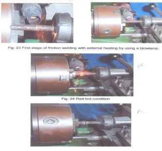
Here one of the work piece is held in a chuck and rotated, other is mounted on static device. When the rotation is started external heat is applied at the joint using a “blowlamp.” When the joints becomes red hot rotation is stopped, external heating source is removed and forging pressure is applied on the stationary work piece, this finishes the weld.
This process is carried out at a constant speed of 490rpm and a constant forge time of 30sec and variable heating time by blowlamp.
Again the specimen fabricated by this process is taken for tensile and shear testing.
This steps involved in external heating can be observed in the following figure removal system in action. The clamp is opened after welding and the spindle is rotated again while the flash is stir hot.
The programmed motion of a cutting tip removes the flash, leaving finished components with no need for further machining.
Procedure
Two mild steel rods of 12mm diameter and length 9mm and 12mm respectively were cut on sawing machine. The work piece to be rotated is clamped in the dynamic holding fixture (chuck) and the spindle is brought to a predetermined speed .the non-rotating component is clamped in a static holding fixture (a milling collect) mounted to a hydraulically actuated tail stock slide.
To heat the work piece to welding temperature the tailstock is a advanced to bring the work pieces in contact under constant axial pressure. When the work pieces are at or slightly above the welding temperature, the spindle motor is switched off and simultaneously forge pressure is order to complete the weld.
10 to 12 mild steel specimens are fabricated at different speeds available on conventional center lathe. Forging time is taken as 30secs for the entire specimen at different speed. These similar weld joints of mild steel are fabricated and taken for tensile and shear testing.
Procedure for external heating
International Journal of Emerging Technology and Advanced Engineering
Website: www.ijetae.com (ISSN 2250-2459,ISO 9001:2008 Certified Journal, Volume 3, Issue 5, May 2013) [image:4.612.119.451.135.444.2]606
Fig 6 Procedure for external heating
III. TENSILE TEST PROCEDURE
Description of machine
Universal testing machine is primarily intended for tensile tests, it can also be use to carry out with suitable accessories a wide variety of other tests such as bending, shear, compression and hardness.
It has two essential parts.
Straining mechanism or loading unit ( on left)
Recording mechanism or control console.
The straining unit consists of a post from base, supporting fair vertical rods. These are 3 cross heads rigidly connected to the columns .the lowest one function on a compression cross head. The middle one is adjustable cross head. It can move vertically up and down .the tension specimen is fixed between adjusted crosshead and the upper tension crosshead. The lower part has the working application cylinder and it is fitted with pipe for pressure application, measurements and oil leakage. These pipes are connected to the console and the rotating beam dynamometer.
These are fair ranges of 10t, 5t, 21/2t, and 1t. The machine can be set for any of these ranges by adjusting the knobs at the dial gauge and weights in the console unit. The record consists of drum on which the graph roll mounted.
Procedure
Fix the specimen in he jaws of the machine. Start applying the load (tensile load) hydraulically. Continue applying the load until the wok piece breaks in to two pieces. Note down the maximum load that the material has withstood. Tabulate the values and draw the maximum load that the relevant graphs.
IV. SHEAR TEST PROCEDURE
Apparatus: compression testing and shear tool
Description of machine
International Journal of Emerging Technology and Advanced Engineering
Website: www.ijetae.com (ISSN 2250-2459,ISO 9001:2008 Certified Journal, Volume 3, Issue 5, May 2013)607
He recording unit consists of the pressure 100 tons, 80tons, and 25 tons. The on-of button and pressure valve vane are provided on the panel.
Shear tool consists of a hollow rectangular block i.e. with a central slit. Holes are made in the walls of block through which the testing specimen is passed. a thin block of rectangular plate of dimension slightly less than of the central slit is made to slide freely inside the central block . The hole in this plate matches with that of central block. The central block also contains provision for a circular plate, having a hole in the center .one or two similar plats can be placed in either sides of central block which has concentrically made grove around the whole central block
The test specimen is passed through these holes and the load is applied on the application of load. It breaks at one or two sections depending on the single or double shear by placing one circular plate for single shear and on either side for double shear.
Procedure
When the test piece into the shear tool such that it passes through the concentric holes of the walls of block and solid block in this case for complete failure the specimen has to break at one section (for single shear) therefore specimen will be in singe shear, place the tool between plates of compression testing machine and then apply the load by pumping oil manually or electrically till the specimen breaks completed record the minimum load at failure.
Hardness test procedure
Apparatus: Rockwell hardness testing machine, microscope and specimen.
Description of machine
It is based on the indentation of hard tip or indenter into the test piece under the action of two consecutively applied loads that are minor (initial)and major (final) in order to eliminate zero error and produces an initial indentation.
A conical shape diamond cone with a 120 apex angle and 0.2 radius is used as an indenter in the Rockwell hardness test for hard materials , for softer materials a hardness steel ball 15mm diameter is used.
V. THEORY
Hardness of a material is defined as the resistance it offers to indentation by another body. The purpose of determining the hardness number is to grade the material, have quality control over the materials to have a rough idea of the tensile strength of the material, which has some relationship with hardness number.
Preparation of specimen
Firstly three mild steel rods of 12mm diameter are welded by friction welding technique at three different speeds. Now a 10mm specimen for testing the hardness is made by cutting 10mm from the weld line. Hardness is measured at exactly 1mm distance farm the weak line so this gives the specimen made by friction welding with external heating.
Procedure
First, a minor load of 10kg is applied by turning by hand wheel till the pointer comes to rests to set position. Then a major load as required is applied is by pulling the lever towards the operator for 15secs. Then Rockwell hardness number is the deference in degree of indentation made by applying the major and minor loads. It is directly read on B and C scale after removing the major load.
Machine specifications
1)Material of the test piece = mild steel 2)Load applied=100kgs
3)Time of application=15secs 4)Thickness of specimen=10mm 5)Indenter used=1/16”
6)Dial gauge used=red
TABLE 1 Materials that can be tested
scale indenter load Materials that can be tested
B 1/16” 100KG Al,brass, copper, mild steel
C Diamond cone
indenter 150KG
International Journal of Emerging Technology and Advanced Engineering
Website: www.ijetae.com (ISSN 2250-2459,ISO 9001:2008 Certified Journal, Volume 3, Issue 5, May 2013)608
VI. ANALYSIS OF MICROSTRUCTURE
Microstructure of the materials was studied to know the changes in the materials caused due to the friction heat produced during the welding process.
Procedure for study of microstructure
After completion o the friction welding the rod was cut using a hacksaw blade at some distance of the joint. These small lengths of the rod cut from the parent material were now prepared for the microstructure of the materials. Following steps were followed for preparation of the specimen.
The pieces were first polished on fine grinding machine till the surface became flat.
Then polished on the emery papers
Lastly they were polished on the polishing machine to get mirror like finish
They were etched in the etch ant for few seconds until there color changed to dull black
The prepared specimen was viewed under microscope aided with a T.V screen.
Structure of parent material none effected zone
Fig7 Structure of parent material none effected zone
Microstructure at 3mm from the joint
Fig9 Microstructure at 3mm from the joint
Clearly it is seen that ferrite (white spots) in the diagram Occupies much space than partite (black spots).
This is a common case in the low carbon steel (0.2%c), which was the material of specimen.
Microstructure at the joint
Fig8 Microstructure at the joint
Microstructure at 3mm from the joint
Fig9 Microstructure at 3mm from the joint
When the metal is heated to red-hot condition pearlier is converted to austenite. When again cool to room temperature the austenite vanishes since it cannot stay at room temperature. This austenite gets converted to peartite again but of larger volume which is seen in the fig 28. Comparing with the Parent metal the pearlite in this case more than in the earlier case.
International Journal of Emerging Technology and Advanced Engineering
Website: www.ijetae.com (ISSN 2250-2459,ISO 9001:2008 Certified Journal, Volume 3, Issue 5, May 2013) [image:7.612.96.237.154.269.2]609
Microstructure after external heatingFig 10 Microstructure after external heating
This region is heated from both the sources one due to friction and from the eternal source from the above structure we can see hat pearlite content has increased to a great
extent when compared with the microstructure of friction of welded joint. Increases in pesrlite ensure increases in both tensile and shear strength.
VII. RESULTS AND DISSCUSSION
Tensile strength results
Case 1 Tensile strength without external source of heating Constant
During friction welding forging time was he constant for 30 sec
friction pressure was maintained constant forging pressure is assumed to be constanTABLE 2
tensile load for friction welded specimens.
Speed (rpm) Forging time (sec) Tensile load (kg)
380 30 1350
490 30 3780
625 30 2150
790 30 3950
980 30 3080
1250 30 4155
1580 30 4210
[image:7.612.116.498.357.554.2]International Journal of Emerging Technology and Advanced Engineering
Website: www.ijetae.com (ISSN 2250-2459,ISO 9001:2008 Certified Journal, Volume 3, Issue 5, May 2013)610
1350 2150
3950 4155 4210
3600
0 500 1000 1500 2000 2500 3000 3500 4000 4500
0 1000 2000 3000
Te n si le lo ad ( K g)
Speed (rpm)
[image:8.612.49.285.130.354.2]Tensile load without External Heating
Fig 11 Tensile load without external heating Vs speed in rpm
The effect of speed can be analyzed from figure.11 which shows that shear strength increases with spindle speed but after the optimum level of speed strength decreases and the reason are same as for tensile strength. Vibration affects the shear strength after the optimum level of spindle speed .the maximum shear load at failure is 5700kg this is obtained at a speed of 1580rpm while the heating time is maintained constant for 30seconds.
Case2: Shear strength with external source of heating Constants
During friction welding forging time was held constant for 30seconds
[image:8.612.317.571.154.532.2]
friction pressure was maintained constant forging pressure is assumed to be constantFig 12 Tensile load without external heating Vs speed in rpm
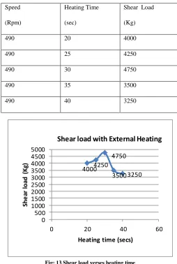
TABLE 3
Shear load with external source of heating
Speed
(Rpm)
Heating Time
(sec)
Shear Load
(Kg)
490 20 4000
490 25 4250
490 30 4750
490 35 3500
490 40 3250
4000 4250 4750
3500 3250
0 500 1000 1500 2000 2500 3000 3500 4000 4500 5000
0 20 40 60
Sh
e
ar
loa
d
(
K
g)
Heating time (secs)
Shear load with External Heating
Fig; 13 Shear load verses heating time
[image:8.612.43.301.550.709.2]International Journal of Emerging Technology and Advanced Engineering
Website: www.ijetae.com (ISSN 2250-2459,ISO 9001:2008 Certified Journal, Volume 3, Issue 5, May 2013)611
Fig14 Shear load without external heatingVIII. HARDNESS TEST RESULTS
Case1: Hardness test of specimens without external heating
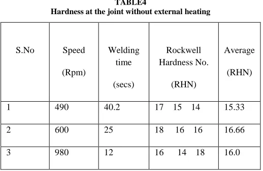
TABLE4
Hardness at the joint without external heating
S.No Speed
(Rpm)
Welding time
(secs)
Rockwell Hardness No.
(RHN)
Average
(RHN)
1 490 40.2 17 15 14 15.33
2 600 25 18 16 16 16.66
3 980 12 16 14 18 16.0
From the above observation we can conclude spindle speed does not show any appreciable change in the hardness of metal at the joint. there is a slight increase in the hardness with the spindle speed up to 600rpm after this optimum level hardness starts decreasing with the speed .600rpm is the optimum Spindle speed at which maximum hardness is obtained .finally we can conclude that there is not much change in hardness with the change in spindle speed.
[image:9.612.37.296.339.508.2]Case2: Hardness test of specimens with external heating
TABLE 5
Hardness at the joint with external heating
S.No Speed
(Rpm)
Welding time
secs
Rockwell Hardness No. (RHN)
Average
(RHN)
1 490 23 18 18 21 19
2 600 14.3 18 19 20 19
3 980 8 16 13 14 14.33
Even in the case of external heating there is not much change in hardness with change in spindle speed. Hardness of the metal at the joint is constant up to 600 rpm after this optimum level hardness value decreases the change in speed. Hardness of the parent metal is 20.33 RHN and the maximum hardness obtained with external heating is 19 RHN, so friction welding by external heating helps the joint in attaining the hardness close to that of the parent metal.
IX. COMPARISON
International Journal of Emerging Technology and Advanced Engineering
Website: www.ijetae.com (ISSN 2250-2459,ISO 9001:2008 Certified Journal, Volume 3, Issue 5, May 2013)612
Now when hardness is considered external heating helps the joint in attaining the hardness of the parent metal. Welding parameters does not show any appreciable effect on the hardness but still external heating does affect the hardness at the joint. So by this we canconclude that friction welding by using an external source is very much useful in imparting good shear strength to the joint.
Now when hardness is considered external heating helps the joint in attaining the hardness of the parent metal. Welding parameter does not show any appreciable effect on the hardness but still external heating does effect the hardness is the joint. So by this we can conclude that friction welding by using an external source is very much beneficial in improving the hardness of the mild steel joint.
So finally we can conclude that friction welding by using an external source increase the tensile and shear strength of the joint by maintaining the hardness
[image:10.612.318.576.157.307.2]Comparing friction welding with other welding techniques: Mild steel rods are welded by Arc welding and MIG welding and their joint strength is compared with friction welding.
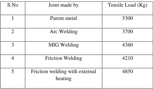
TABLE 6
Comparison of friction welding technique with others
So from above observation it can be concluded that friction welding with external heating produces a strong joint compared to other welding process. The tensile strength of friction welded joint by external heating is almost near to tensile strength of parent metal.
[image:10.612.52.560.430.576.2]Power calculations table
TABLE 7 Power calculation table
Welding
condition
Speed
(Rpm)
Welding time
(sec)
Power
(KW)
Total power
consumed
(Kwhr)
Power per
With external heating
490 15 144 0.00583 58.3
Without external heating
1580 15 4.2 0.0175 175
This study investigate the effects of spindle rotational speed and external heating on tensile breaking strength and shear strength of mild steel joint. Following inferences can be made as a result of this experimental study.
At constant forge load, the tensile breaking strength of mild steel joints is maximum at a speed of 1580rpm.
By external heating tensile strength is obtained at 490rpm is higher than tensile strength obtained at 1580rpm without external heating .
At constant forge load, the maximum shear strength is obtained at speed of 1580rpm.
By external heating at constant speed of 490rpm maximum shear strength is obtained for heating time of 30secs
Spindle speed does not show any appreciable change in hardness of mild steel joint.
By external heating maximum hardness obtained is 19RHN, which is close to the hardness of parent metal.
S.No Joint made by Tensile Load (Kg)
1 Parent metal 5300
2 Arc Welding 3700
3 MIG Welding 4360
4 Friction Welding 4210
5 Friction welding with external heating
International Journal of Emerging Technology and Advanced Engineering
Website: www.ijetae.com (ISSN 2250-2459,ISO 9001:2008 Certified Journal, Volume 3, Issue 5, May 2013)613
Joints welded by friction welding with externalheating have higher strength compare to other welding process.
By external heating power of 116.7Kwhr can be saved for manufacturing of 10000peices.
Annual saving of Rs:2,12,977.5 is possible by using external heating
REFERENCES
[1 ] “Experimental study on effects of spindle speed and forge load on tensile strength of similar tubular weld joints of aluminum and GI pipes” By J.singh(Indian institute of engineers journal).
[2 ] “Mechanical properties and microstructures of inertia friction welded 416 stainless steel”. By K.S.Mortensen,C.G.Jensen ,L.C.Conrad,and Losee.
[3 ] “Effect of friction welding on carecteristics of titanium /A5083 aluminium alloy joint “.Report1:joint mechanical properties .By Akiyoshi FUJI,Thomas H.NORTH,Massaki KIMURA and kei AMEYAMA.
[4 ] “Fatigue strength of friction stir welded joints in aluminium”.By Mats Ericsson,department of material science and engineering, royal institute of technology.
[5 ] “Fundamentals of welding”. By OP.Khanna. [6 ] “Metallurgy and material science” By Dieter. [7 ] “Hand book of metallurgy “By Avnar. [8 ] “Strength of materials “By Ramamurtham.
Links:
American friction welding(AFW)
Thompson friction welding(TFW)
The welding institute(TWI)
NCT friction welding