Evanescent Fields Inside a Cut-off Waveguide as Near
Fields
Zhi-Yong Wang, Jun Gou, Shuangjin Shi, Qi Qiu
School of Optoelectronic Information, University of Electronic Science and Technology of China, Chengdu, China Email: [email protected]
Received 2013
ABSTRACT
Usually, electromagnetic evanescent waves are some kinds of near fields. However, it looks as if the evanescent waves inside a cut-off waveguide had nothing to do with any near field. In this paper, we will show that the evanescent waves inside a cut-off waveguide can also be regarded as the near fields of an aerial array.
Keywords: Evanescent Fields; Cut-off Waveguide; Near Fields
1. Introduction
From the point of view of classical field theory, an eva-nescent wave is a standing wave with an intensity that exhibits exponential decay with distance from the boundary at which the wave was formed. As far as elec-tromagnetic evanescent waves are concerned, for exam-ple, they are formed when waves travelling in a medium undergo total internal reflection at its boundary; they also are found in the near field region of an antenna, where the antenna emits electromagnetic fields into the sur-rounding near field region, and a portion of the field en-ergy is re-absorbed provided that there is no receiver, while the remainder is radiated as electromagnetic waves. In quantum mechanics, the evanescent-wave solutions of the Schrödinger equation give rise to the phenomenon of quantum tunneling. In optics, evanescent wave coupling is a process by which electromagnetic waves are trans-mitted from one medium to another by means of the evanescent, exponentially decaying electromagnetic field. Mathematically, the process is the same as that of quan-tum tunneling, except with electromagnetic waves in-stead of quantum-mechanical wavefunctions. As a result, people call the process photonic quantum tunneling.
Usually, electromagnetic evanescent waves are some kinds of near fields (e.g., the ones in total internal reflec-tion). However, it looks as if the evanescent waves inside a cut-off waveguide had nothing to do with any near field. In this paper, by means of another way of looking at the guided waves, we will show that the evanescent fields inside a cut-off waveguide can be regarded as the near fields of an aerial array.
2. Another Way of Looking at the Guided
Waves
Let us assume that a hollow rectangular waveguide is placed along the direction of z-axis, and the waveguide is a straight perfect metal pipe with the transversal dimen-sions a and b (a>b, the cross-section of the waveguide lies in 0≤x≤a and 0≤y≤b).
For convenience let us just consider the TE10 mode, in which the transverse electric field is perpendicular to z-axis and with only a y-component Ey that will vary with x and z. In terms of the frequency ω and wave-number vector k( , , )k k kx y z (with ), the transverse electric field Ey can be written as
0 y k
0sin exp[i( )],
y x z
E E k x t k z (1) where E0 is a constant factor. For the TE10 mode,
π
x
k a and 2 2 π2 2
z
k c a are the wavenum-bers along the x- and z-axis directions, respectively, where c is the velocity of light in vacuum. The cutoff frequency of the TE10 mode is c k cx πc a. There are no charges in the free space inside the waveguide, such that Ey must satisfy the wave equation
2 2 2 2
2 2 2 2 2 0.
y y y y
E E E E
x y z c t
(2)
According to the traditional waveguide theory one has: 1) for c, the electromagnetic field inside the wave- guide is the propagation mode (i.e., the travelling wave), and its phase and group velocities are
2
p z 1 ( c )
v k c
and 2
g z 1 ( c )
respectively. For the moment, one has kz2π g ,
where 2
0 1 ( 0 2 )
g a
is the wavelength of the oscillation along the z-direction (i.e., the guide wave-length), and it is different from the free-space wavelength
0 2πc
of electromagnetic waves of the same fre-quency. 2) for c, i.e., 02a, the wave number
z
k (and also g) becomes imaginary, it follows from Eq. (1) that EyE0sink xx exp(z)exp(it), where
2 2 c c,
then the electromagnetic field inside the waveguide oscil-lates with time as exp(i )t and varies with z as exp(z), and is called the evanescent field.
For our purpose, let us discuss another way of looking at the guided waves [1]. For the TE10 mode described above, the vertical dimension (in y) had no effect, so we can ignore the top and bottom of the waveguide and imagine that the waveguide is extended indefinitely in the vertical direction. Then the waveguide can be imag-ined as just consisting of two vertical plates with the separation a. Let’s say that the source of the fields is a vertical wires placed in the middle of the waveguide, with the wire carrying a current that oscillates at the fre-quency ω. In the absence of the waveguide walls such a wire would radiate cylindrical waves. Consider that the waveguide walls are perfect conductors, the conditions at the surface will be correct if we add to the field of the wire the field of one or more suitable image wires. The image idea works just as well for electrodynamics as it does for electrostatics, provided that we also include the retardations. Now let’s take a horizontal cross section, as shown in Figure 1, where W1 and W2 are the two guide
a S Line source
S S S
S
S
S
Image sources Image sources
W1
W2
[image:2.595.311.534.419.708.2]Waveguide
Figure 1. The line source S0 between the conducting plane walls W1 and W2.
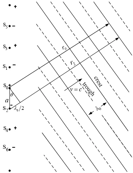
walls and S0 is the source wire. Assume that the direction of the current in the wire is positive. Now if there were only one wall, say W1, one could remove it if an image source (with opposite polarity) were placed at the posi-tion marked S1. But with both walls in place there will also be an image of S0 in the wall W2, which is shown as the image S2. This source, too, will have an image in W1, which is called S3. Now both S1 and S3 will have images in W2 at the positions marked S4 and S6, and so on. For our two plane conductors with the source halfway be-tween, the fields are the same as those produced by an infinite line of sources, all separated by the distance a. For the fields to be zero at the walls, the polarity of the current in the images must alternate from one image to the next. In other words, they oscillate 180 out of phase. The waveguide field is, then, just the superposition of the fields of such an infinite set of line sources.
The walls can be replaced by the infinite sequence of image sources.
Let us look at the fields which arrive at a large dis-tance from the array of image sources. The fields will be strong only in certain directions which depend on the frequency—only in those directions for which the fields from all the sources add in phase. At a reasonable dis-tance from the source the field propagates in these spe-cial directions as plane waves. Such a wave is sketched in Figure 2, where the solid lines represent the wave
0
5
s
3
s
1
s
0
s
2
s
4
s
6
s
a
0 2
v c
0
r
2
[image:2.595.60.288.496.708.2]r
crests and dashed lines represent the troughs. The wave direction will be the one for which the difference in the retardation for two neighboring sources to the crest of a wave corresponds to one-half a period of oscillation. In other words, the difference between r2 and r0 in the fig-ure is one-half of the free-space wavelength: r2 r0
0 2
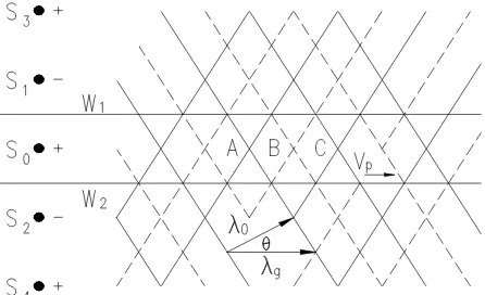
. The angle θ in then given by sin 0 2a. There is, of course, another set of waves traveling downward at the symmetric angle with respect to the array of sources. The complete waveguide field (not too close to the source) in the superposition of these two sets of waves, as shown in Figure 3. The actual fields are really like this, of course, only between the two walls of the waveguide.
At points like A and C, the crests of the two wave pat-terns coincide, and the field will have maximum, and points like B, both waves have their peak negative value, and the field has its minimum (largest negative) value. As time goes on the field in the guide appears to be trav-eling along the waveguide with wavelength g, which is the distance from A to C. That distance is related to θ by
0
cos g , using sin 0 2a, one has 2 0 cos 0 1 ( 0 2 ) ,
g a
(3) which is just what we found before.
Now we see why there is only wave propagation above the cutoff frequency c. If the free-space wavelength is longer than 2a, there is no angle where the waves shown in Figure 2 can appear. The necessary constructive in-terference appears suddenly when λ0 drops below 2a, or when ω goes above c πc a. If the frequency is high enough, there can be two or more possible directions in which the waves will appear. In general, it could happen when 0a
sin
. These additional waves correspond to the higher guide modes. It has also been made evident by our analysis why the phase velocity of the guided waves is greater than c and why this velocity depends on ω. As ω is changed, the angle of the free waves of Figure 2 changes, and therefore so does the velocity along the waveguide. Although we have described the guided wave as the superposition of the fields of an infinite array of line sources, one can see that we could arrive at the same result if we imagined two sets of free-space waves being continually reflected back and forth between perfect mirrors—remembering that a reflection means reversal of phase. These sets of reflecting waves would all cancel each other unless they were going at just the angle θ given in 0/ 2a.
3. Evanescent Fields Inside A Cut-Off
Waveguide as Near Fields
As shown in Figures 1-3, if we are close to the sources, the field is very much like the static fields. Here the av-erage source strength is zero, because the sign alternates
Figure 3. The waveguide field can be viewed as the super-position of two trains of plane waves.
from one source to the next. In other words, close to the source, we see the field mainly of the nearest source; at large distances, many sources contribute and their aver-age effect is zero. So now we see why the waveguide below cutoff frequency gives an exponentially decreas-ing field. At low frequency, in particular, the static ap-proximation is good, and it predicts a rapid attenuation of the fields with distance (on the other hand, at high fre-quencies the retardation of the fields can introduce addi-tional changes in phase which can cause the fields of the out-of-phase sources to add instead of canceling, such that the waves can propagate, just as discussed in Section 2). This implies that evanescent fields inside the cutoff waveguide have a close relationship with near fields.
In fact, in frustrated total internal reflection, evanes-cent fields are directly identical with near fields consist-ing of virtual photons [2,3], these virtual photons corre-spond to the elementary excitations of electromagnetic interactions. Now we will show that evanescent fields inside an undersized waveguide are also identical with near fields and then consist of virtual photons. As we know, the near fields of a dipole antenna fall off with the distance r from the antenna like 1rn ( ). However,
if we assume that an aerial array formed by an infinite set of infinite-length line sources arranging in a periodic manner, then the near fields of the aerial array falls off like
2
n
exp(r), from which one can show another way of understanding why a waveguide attenuates the fields exponentially for frequencies below the cutoff frequency.
[image:3.595.314.537.85.221.2]guided wave in the limit of 0, the grid is taken as an array of parallel wires lying in a plane, where the wires are infinitely long and with a uniform spacing of a between them, and carry uniform charge with the sign alternates from one source to the next, such that the grid’s period is 2a. At a large distance above the plane of the wires, the electric field vanishes because of the grid being neutral in total. While, as we approach the grid of wires, the field begins to deviate from which one found at large distances from the grid. The closer one gets to the grid, the larger the variations. Traveling parallel to the grid, one observes that the field fluctuates in a peri-odic manner. Any periperi-odic quantity can be expressed a sum of sine waves (Fourier’s theorem). If the wires lie in the xy-plane and run parallel to the y-axis, one has
( , ) ( )sinπ ,
yn n
E x z F z nx a (4) where n is the harmonic number (we have assumed long wires, so there should be no variation with y). A com-plete solution would be made up of a sum of such terms for . Eq. (4) must satisfy Laplace’s equation in the region above the wires (there are no charges), i.e.,
1, 2,3... n
2 2 2 2 0
yn yn
E x E z
, using Eq. (4) one has
2 2 2
2 2 d π , d n n F n F
z a (5)
it follows that F zn( )Enexp(nz), where nn aπ , , and are the constant coefficients, then Eq. (4) becomes
1
n En
( , ) sin(π )exp( ).
yn n n
E x z E nx a z (6) That is, each Fourier component of the field will de-crease exponentially with a characteristic distance 1 n
π
a n
. In other words, the near fields of the aerial array falls off like exp(nz). Comparing Eq. (1) with Eq. (6), one can find that the static field with n=1 is equivalent to the guided wave of the TE10 mode in the limit of 0, such that the evanescent field inside the cut-off waveguide is equivalent to the near field of the aerial array. To show that the TE10 mode with the frequency
c
0 is equivalent to the near field of the aerial array, that is, to obtain Eq. (1) with 0 c from Eq. (6) with n=1, one ought to make the replacement of
c 0 0
, such that one has the following replacements:
c
0 0 ,
(7) 1 exp(i 0 ) t exp(i ),t (8)
2 2 2 2
c c
π 1 0 1 i ,
z k
a c c
(9)
( , ) ( , , )
y y y y
E E x z E E x z t (10)
2 2 2 2 2
2 2 2 2 2 2
( )Ey 0 ( )
x z x z c t
Ey 0, (11)
0
0 π
( , ) sin( )exp( )
π
( , , ) sin( )exp(i ), y
y
x
E x z E z
a x
E x z t E t z
a (12)
where 1, Ey Ey1, kz 2 c2π2 a2 . As
shown in Fi presence of the decay factor )
z
gures 2-3, the
exp( impli field y
ex-ists in the neighborhood of the aerial array, and then is the nea ield of the aerial array. , evanescent fields inside an undersized waveguide can also be de-scribed as near fields, such that the field quanta of eva-nescent fields inside the undersized waveguide are also virtual photons.
It is important to note that, from the point of view of quantum mechanics, as a wavepacket falls off with a di
es that the E x z ty( , , ) mainl
r f Therefore
stance L, it is the probability of photons propagating the distance of L that decays with L. Therefore, though a wavepacket inside a barrier contains an exponentially decay factor such as exp(r), it is not implies that inside the barrier the wavepacket exponentially decays with the propagation d That is, the particle or wave packet which has entered the barrier is not attenu-ated, because the reflection takes place at the barrier front, where the barrier length only determines exponen-tially how many photons are reflected at the front already. All discussions here are similar for any evanescent field inside a cut-off waveguide.
4. Conclusions and Discusses
istancer.fields inside a cut- near fields, owing
the Fundamental Research ersities (Grant No: ZYGX
REFERENCES
[1] R. P. Feynman, R. B. Leighton and M. Sands, “Feynman Lectures on P y, New York, Vol. 2, 1964.
In this paper, we show that evanescent off waveguide are also identical with
to which, in fact, many theoretical and experimental in-vestigations have presented a conclusion that the eva-nescent fields of the electromagnetic field can superlu-minally propagate [4-9], which are also due to the super-luminal behaviors of near fields and does not violate causality.
5. Acknowledgements
This work was supported by Funds for the Central Univ 2010X013).hysics,” Addison-Wesle
[2] S. T. Ali, “Evanescent Waves in Quantum Electrody-namics with Unquantized Sources,” Physical Review D,
Vol. 7, 1973, pp. 1668-1675.
Klu-35-5
wer Academic/plenum Publishers, New York, 1999. doi:10.1007/978-1-4615-48
[4] Z. Y. Wang, C.D. Xiong and B. He, “Alternative Per-spective on Photonic Tunneling,” Physical Review A, Vol. 75, 2007, pp. 013813-013820.
doi:10.1103/PhysRevA.75.013813
[5] Z. Y. Wang, C. D. Xiong and B. He, “Superluminal Propagation of Evanescent Mod
Annalen der Physik (Berlin) Vol.17, 200es as A Quantum Effect,” 8, pp. 319-325. [6] Z. Y. Wang, W. C. Wang and Q. Qiu, et al., “Average and Instantaneous Velocities of Energy of Evanescent
Modes,” Physical Review A, Vol. 83, No. 5, 2011, pp. 053827-053831.
doi:10.1103/PhysRevA.83.053827
[7] G. Nimtz, “On Superluminal Tunneling,” Progress in Quantum Electronics, Vol. 27, 2003, pp. 417-450. [8] A. M. Steinberg, P. G. Kwiat and R. Y. Chiao,
“Meas-urement of the Single-Photon Tunneling Time,” Physical Review Letters, Vol.71, 1993, pp. 708-711.