ISSN Online: 2152-2308 ISSN Print: 2152-2294
Selection of Optimal Beam Forming Algorithm
for Mobile Ad Hoc Networks
Mohammed Tarique
Department of Electrical Engineering Ajman University of Science and Technology, Fujairah, United Arab Emirates
Abstract
Ad hoc networks have drawn considerable attentions of researchers for the last few years. Various applications of ad hoc networks have been reported in the literatures including disaster management, battle field, environmental management, healthcare, and smart grid. Ad hoc networks have some limita-tions namely short operating life, unreliability, scalability, delay, high interfe-rence, and scarce resources. In order to overcome these limitations, numerous researches have been carried out. Smart antenna integration is one of them. It has been shown in the literatures that smart antenna can improve network’s capacity, increase network lifetime, reduce delay, and improve scalability by directing antenna radiation pattern in a desired direction. But, producing a desired antenna radiation pattern is not a simple task for resource constraint ad hoc networks. A careful selection of beam forming algorithm is required. In this paper we show that smart antenna system, consisting of circular mi-crostrip antennas and arranged in a linear arrangement, is the most suitable choice for ad hoc network. We compare a number of smart antenna algo-rithms in this paper under different noisy conditions. We show that the Least Square Constant Modulus (LSCM) and Least Constant Modulus (LCM) algo-rithms outperform other algoalgo-rithms in terms of directivity and minimized side lobes.
Keywords
Ad Hoc Networks, Microstrip, Antenna Array, Smart Antenna, Beam Forming, DSP
1. Introduction
Recent developments in electronic devices like laptop computers, personal digi-tal assistant (PDA), pagers, and cellular phones have become portable and “smart” now. It is very common that users roam with these devices at any place
How to cite this paper: Tarique, M. (2017) Selection of Optimal Beam Forming Algo-rithm for Mobile Ad Hoc Networks. Wire-less Engineering and Technology, 8, 20-36.
http://dx.doi.org/10.4236/wet.2017.81002
Received: December 19, 2016 Accepted: January 21, 2017 Published: January 24, 2017
Copyright © 2017 by author and Scientific Research Publishing Inc. This work is licensed under the Creative Commons Attribution International License (CC BY 4.0).
and at any time. Hence, there is need for a network that users can connect with on a temporary basis. Ad hoc network is considered a suitable solution for this kind of temporary network. Ad hoc network consists of a number of mobile nodes. It is self-organizing and self-configuring. No network infrastructure is required to set up this type of network. Based on these attractive features many applications of ad hoc network have already been introduced. Some of these ap-plications include crisis management, search and recuse, telemedicine, tele- geoprocessing, process control, personal communication, virtual navigation, education, and security [1].
Ad hoc network has limitations too. It has dynamic topology. Mobile nodes join and leave the network at any time. Hence, route “breakage” is a very fre-quent phenomenon in ad hoc network. Other limitations include high packet loss, unreliability, high interference and noise, and limited range. Like other wireless systems wireless medium is shared by a group of mobile nodes. Moreo-ver, mobile nodes communicate with each other in a multi-hop fashion. Hence, ad hoc network can support only a limited bandwidth to an individual user. In order to improve bandwidth many researches have been carried out for the last decade. Smart antenna integration is one of them.
Smart antenna enables mobile node to radiate power in a specified direction. It also helps mobile nodes to reduce interference level in a network by steering radiation’s nulls toward the sources of interference. Hence, a number of simul-taneous transmissions can occur at the same time as shown in Figure 1. Smart antenna also allows a mobile node to adjust its transmission power to a required minimum level and hence improves the network life-time. There are other ad-vantages of using smart antenna in ad hoc networks. These adad-vantages have been comprehensively studied in the literatures [2]-[12].
[image:2.595.211.537.559.712.2]In this paper we investigate effective and efficient smart antenna design strat-egy for mobile ad hoc networks. We consider two different antenna elements in this investigation namely circular microstrip antenna and rectangular microstrip antenna. We compare the performances of these two antennas in order to select a suitable antenna element for smart antenna design. We also consider three different antenna arrangements namely linear, planar, and circular. In addition,
we investigate a number of smart antenna algorithms in order to select an opti-mum algorithm for mobile ad hoc networks. The rest of the paper is organized as follows. Some related works have been presented in Section 2. A brief intro-duction to microstrip antenna has been presented in Section 3. The perfor-mances of rectangular and circular microstrip antennas have been investigated and compared in the same section. The smart antenna design algorithms for Ad hoc network have been presented in Section 4. This paper has been concluded with Section 5.
2. Related Works
Numerous research activities have been done so far in order to improve the bandwidth of ad hoc networks. Most of the researches have been investigated based on the assumption that mobile nodes are equipped with omnidirectional antenna. With omnidirectional antenna mobile nodes radiate signal equally in all surrounding area and all mobile nodes within the transmission range receive that signal. Due to the omnidirectional radiation and imposed medium access control (MAC) algorithm the neighboring nodes remain standby during their transmission to avoid packet collision. Hence, network throughput is reduced. In order to increase network throughput smart antenna integration has been suggested for ad hoc network [2]-[11].
One of the earliest works on smart antenna application in ad hoc network has been presented in [2]. The interaction and integration of critical components of smart antenna have been addressed in this paper. The authors have shown that the performance of an ad hoc network highly depends on the adaptive beam forming algorithm and signal processing algorithm. The authors focused on the antenna pattern, training sequences, direction of arrival algorithm, and the an-tenna coupling effects.
In [3] the authors suggest smart antenna for wireless ad hoc networks instead of omnidirectional antennas. The authors claim that smart antenna at each mo-bile node facilitates simultaneous transmission of packets and hence improves the network throughput. The authors show via simulations that it is preferable to use the beamforming technique over the switched beam technique in order to obtain a high throughput.
A novel MAC protocol based on directional antenna has been presented in [4]. By using this protocol, source and destination nodes determine each other’s di-rections. The source node sends data packets in the given direction. Hence, the interference level is reduced and network throughput is improved. The author compared the performances of the network for two cases-using omnidirectional antenna and using directional antenna. The simulation experiments presented in [4] show that the proposed protocol, with 4 directional antennas per node, in-creases the average throughput of the network by 2 to 3 times.
and antenna gain for the adaptation of antenna pattern. The simulation results show that DVCS protocol can improve the network capacity by a factor of 3 to 4 for a small ad hoc network consisting of 100 nodes compared to omni-direc- tional antenna based ad hoc network of the same size.
In [6] the authors suggest that directional antennas to be used for ad hoc net-works instead of omni-directional antenna. They also suggest that existing MAC protocols need to be modified in order to take the advantages of directional an-tennas. Current MAC protocols, including popularly used IEEE 802.11 standard, have been designed for omnidirectional antenna. The authors have presented a new MAC protocol that is suitable for ad hoc networks based on directional an-tennas.
A distributed receiver-oriented multiple access (ROMA) channel access sche-duling protocol has been presented in [7]. The ROMA protocol uses directional antennas to form multiple directional radiation pattern to ensure several simul-taneous communications. The ROMA protocol activates a number of links in a time slot. The results presented in [7] show that a significant improvement on the network throughput can be achieved by using the ROMA protocol.
Capacity of ad hoc networks based on directional antenna has been formu-lated in [8]. The authors argued that directional antennas can support a number of simultaneous connections. But, there is a limit on such type of concurrent communications because of the mutual interference. Hence, there is a bound on the amount of capacity improvement. The network capacity bound depends on the specific antenna type and higher layer protocols. In [8] the authors calculate interference based capacity bounds for a generic antenna model and a real-world antenna model.
In a similar work [9] the authors have used beamforming antennas to increase the transmission range and also to reduce the interference level in ad hoc net-works. The authors have considered a number of enhancements including “ag-gressive” and “conservative” channel access mechanisms based on beamforming antennas, link power control, and directional neighbor discovery. Two ap-proaches of beam forming algorithms have been used namely steered and switched beams. The results show that beamforming improves network perfor-mance by 28% - 118% depending upon the node density. The results also show that network delay can also be reduced by a factor of 28 by using appropriate beamforming algorithm.
Another energy saving MAC protocol for mobile ad hoc networks, utilizing directional antennas, has been presented in [11]. It is shown that directional an-tenna can help to achieve higher directivity and hence to achieve higher anan-tenna gain. Thus, mobile node can reduce transmission power to a minimum level and can save energy. The simulation results presented in [11] show that the proposed MAC protocol not only saves energy but also maximizes network throughput.
Most of these above mentioned works focus on the performance improvement of ad hoc network by directional antenna. In this paper a design strategy for smart antenna integration in ad hoc networks has been presented. Microstrip antenna has been used as the antenna element in smart antenna design. In this work two different microstrip antennas have been considered namely rectangu-lar microstrip and circurectangu-lar microstrip. In this investigation the performances of these two types of antennas have been compared. Three different types of an-tenna array namely linear, planar, and circular have been investigated in this work. It has also been shown that the planar and circular antenna arrays require extensive signal processing and hence they are not suitable for resource con-straint ad hoc networks. In this work we also investigate a number of smart an-tenna algorithms namely Least Mean Square (LMS), Sample Matrix Inversion (SMI), Recursive Least Square (RLS), Constant Modulus (CM), Least Square Constant Modulus (LSCM), Conjugate Gradient Method (CGM), and Spreading Sequence Array Weights (SSAW). Based on this investigation we recommend a suitable algorithm for smart antenna for mobile ad hoc networks. None of the previously mentioned related works have addressed these issues.
3. Microstrip Antennas
Microstrip antennas have been widely used in wireless communication, mobile radio, spacecraft, missiles, aircraft and satellite since 1970. These wide spread applications of microstrip antennas became possible because of its low cost, small size, and easy installation. The most attractive feature of microstrip an-tennas is that they can be easily integrated and fabricated onto anelectronic cir-cuit board. Microstrip antenna can be found in different shapes including rec-tangular, circular, square elliptical, dipole, ring, and triangular. Among these shapes rectangular and circular shapes have become popular in antenna array design.
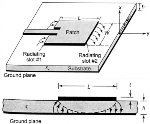
A rectangular microstrip antenna is shown in Figure 2. It consists of a very thin metallic strip placed on dielectric substrate. The thickness of the microstrip is usually less than free space wavelength (i.e., λ0 = c/f) and the substrate
thick-ness varies between 0.003λ0 and 0.05λ0. The rectangular strip is placed on the
substrate in a way so that the maximum antenna radiation occurs along the di-rection that is normal to the microstrip. The length of the microstrip, L varies between 1/3λ0 to 1/2λ0. A number of dielectric substrates, with the dielectric
constant, ϵr from 2.2 to 12, are used in microstrip antenna.
Figure 2. Rectangular microstrip antenna.
90˚, and 270˚ ≤ φ ≤ 360˚) is given by
(
)
0 0
0 sin cos cos sin
2 2
sin 2π
e
hk k L
c E hk c θ φ φ = (1)
The normalized radiation field for the H-pane
(
0 0 0)
0 , 0 180 ϕ= ≤ ≤θ is given by0 0
0
sin sin sin sin cos
2π 2π sin 2π hk Wk c c E hk c φ
θ θ θ
= (2)
where Le = effective length, and k0 = 2π/λ0. The microstrip antenna is feed by a
microstrip transmission line as shown in Figure 3. The input impedance of this transmission line can be varied by adjusting the length of y0. In order to plot the
field patterns, we use the MATLAB program provided in [13]. The plots for the fields in E-plane and H-plane are shown in Figure 4. The other design parame-ters used in producing the field pattern have been listed in Table 1. The other values produced by the program are as follows: effective length Le = 1.0685 cm,
E-plane Half Power Beam Width (HPBW) = 88˚, H-plane Half-Power Beam Width (HPBW) = 76˚, directivity, D0 = 5.3514, resonant input resistance at feed
point Rin = 228 Ω.
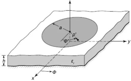
A circular microstrip antenna is shown in Figure 5. The construction of a circular microstrip antenna is similar to that of a rectangular microstrip antenna. Only the shape of the metallic strip is circular rather than rectangular.
The normalized radiation field for a circular microstrip antenna in the E-plane
(
θ =90 , 0 ≤ ≤ϕ 90 , and 270 ≤ ≤ϕ 360)
is given by( )(
)
( )(
)
0 sin 0 e 2 sin 0 e
Figure 3. The feed mechanism of microstrip antenna.
Figure 4. The field patterns of rectangular microstrip antenna.
Figure 5. Circular microstrip antenna.
The normalized radiation field for the same in the H-pane
(
ϕ=0 , 0 ≤ ≤θ 180)
is givenby
( )(
)
( )
( )(
)
( )
0 sin 0 e cos 2 sin 0 e cos
Table 1. Rectangular microstrip design parameter.
Parameter Values
Length, L 0.9 cm
Width, W 1.20 cm
Substrate height, h 0.16 cm
Feed lenegth, y0 0.313 cm
Dielectric constant, εr 2.2
Resonant Frequency, f0 10 GHz
where J0
( )
x is the zeroth order Bessel function, J2( )
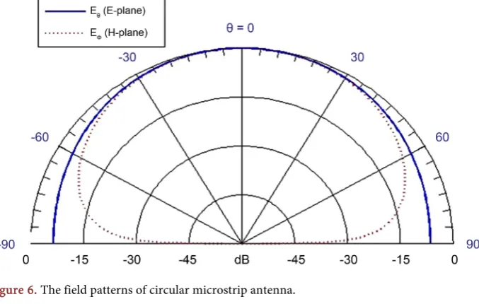
x is the second order Bessel function, ae is the effective radius. In order to compare the field patternsfor circular microstrip antenna with those of rectangular microstrip antenna we maintain the same metallic surface area. We also maintain the same substrate height. Plots of the E-plane and H-plane field patterns for the circular microstrip antenna of same area are shown in Figure 6. The other parameters used to pro-duce the field patterns are as follows: effective radius ae = 0.5985 cm, the E-plane
HPBW = 92˚ and the H-plane HPBW = 78˚, the directivity is 5.5272, the input resistance at feed point is 228 Ω.
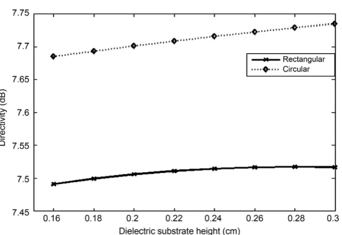
The directivity of circular microstrip and rectangular microstrip antennas are illustrated in Figure 7 and Figure 8. It is shown in Figure 7 that directivity vari-ations for both investigated antennas are not much different when different di-electric materials are used. But, the directivities vary with respect to the height of dielectric material as shown in Figure 8. This figure depicts that the circular mi-crostrip antennas achieve high directivity compared to its rectangular counter-part. Hence, we consider circular microstrip antenna for the rest of the work presented in this paper.
4. Optimal Smart Antenna Algorithms
Smart antenna system is composed of a collection of two or more antenna ele-ments called antenna array. These antenna eleele-ments work together to establish a unique radiation pattern. A functional block diagram of a smart antenna system is shown in Figure 9. Adaptive algorithm is the main functional component of a smart antenna system. Smart antenna system can locate and track desired signal called signal of interest (SOI) and also signal of no interest (SNOI) by adjusting the antenna weights. By using adaptive algorithms, the smart antenna system can dynamically adjust radiation of the antenna elements so that the resultant radiation is directed along the SOI and it can suppress the radiation patterns along the direction of SNOIs. In order to track the radiation pattern direction of arrival (DOA) algorithm is used. The DOA algorithm helps the antenna ele-ments to set the desired excitation weights in terms of magnitude and phase so that the radiation can be directed in a desired direction.
Figure 6. The field patterns of circular microstrip antenna.
Figure 7. Variation of directivity with respect to dielectric constant.
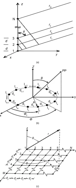
These arrangements are associated with different level of complexity in design and implementation. A number of investigations have been carried out in order to determine a suitable arrangement for ad hoc network. Among these antenna array arrangements linear array is the simplest one and we used it for this inves-tigation. In linear arrangement all antenna array elements are aligned along a straight line. We assume that antenna elements are equally spaced by a distance d. We also assume that the far-field condition is satisfied (i.e., rd).
[image:9.595.192.534.316.531.2]Figure 8. Variation of directivity with respect to dielectric substrate height.
Figure 9. Smart antenna system.
algorithms. These algorithms are suitable for static networks because of their fixed beam forming characteristic. In these networks the signal arrival angle is fixed. Once array weights are determined by the above mentioned algorithm they do not change over the time.
(a)
(b)
(c)
[image:11.595.243.505.63.707.2]this work. In this work we choose some popular algorithms namely LMS algo-rithm, Sample Matrix Inversion (SMI), Recursive Least Square (RLS), Constant Modulus Algorithm (CMA) and Least Square Constant Modulus Algorithm (LCMA).
The LMS algorithm, proposed in [15], is a gradient based algorithm. It is as-sumed in this algorithm that there exists a quadratic performance surface. The performance surface is in the shape of elliptic paraboloid having one minimum. A gradient algorithm has been used to establish the minimum condition. An iterative technique called the method of steepest descent has been used in order to determine the gradient of the cost function. By using the algorithm, the weights of the antenna elements are determined by using LMS method intro-duced in [16] [17].
In order to design smart antenna system for ad hoc network using LMS algo-rithm we use the MATLAB program provided in [14]. Since the mobile nodes in ad hoc networks have limited processing power, we would like to choose a minimum number of antenna elements to achieve a desired radiation pattern. The antenna weights are approximated by
(
)
( )
1( )
( )
1
2
w k+ =w k − µ ∇w J w k (5)
where µ is the step-size, ∇w is the gradient of the performance surface, and
( )
J w k is the cost function. Determining the step size is important for this algorithm and it affects the convergence of the LMS algorithm. If the step size is too small, the convergence of the algorithm will be slow and the adaptive array faces problem to determine the angle of signal arrival. If the step size is too large, the LMS algorithm overshoots and it becomes difficult to achieve optimum weights for the antenna array. It has been shown in [15] that the most suitable value of the step size is set by
max 1 0 2 µ λ
≤ ≤ (6)
where λmax is the largest value of the correlation matrix of signal vector. In this
work we choose µ=2λmax.
The Sample Matrix Inversion (SMI) is another popular algorithm. This is an improved version of LMS algorithm. The SMI algorithm has been introduced in order to overcome the limitation of LMS algorithm, which requires many itera-tions before convergence. On the other hand, the SMI algorithm converges quickly [15] [17]. Hence, it is considered more suitable when the signal charac-teristics are rapidly changing. This type of rapid signal change is very common in ad hoc network environment. The sample matrix used in this algorithm is a time average estimate of the array correlation matrix using K-time samples and is given by
( ) ( )
1 1
ˆ K H
xx i
R i i
K =
=
∑
x x (7)( ) ( )
1 1 ˆ K ir d i i
K ∗ =
=
∑
x (8)where d k
( )
is the desired signal and x k( )
is the arriving signals. Theweights for the array antenna elements are given by
( )
1( )
xx
w k =R−r k (9)
Although the SMI algorithm is faster than the LMS algorithm, the computa-tional burden is one of the major drawbacks of the SMI algorithm. In order to overcome this, the Recursive Least Square (RLS) algorithm has been introduced. In RLS algorithm the required correlation matrix and the correlation vectors are calculated recursively. In the LMS algorithm more emphasis is given on the re-cent data samples and less emphasis is given on the past data samples. In this algorithm the sample matrix is given by
( )
1( ) ( )
1
K
k H
xx i
R k α − i i
=
=
∑
x x
(10)
The correlation vector r can be estimated by
( ) ( )
1 1 ˆ K k ir α −d∗ i i
=
=
∑
x (11)where α is the weight factor. The advantage of the RLS algorithm over SMI is that it is no longer necessary to invert a large correlation matrix. Moreover, the RLS algorithm converges much more quickly than the LMS algorithm.
In many wireless systems the transmitted signal has constant amplitude. This signal is usually affected by multipath propagation that causes signal amplitude to change. Moreover, the constant amplitude property is also affected when the channel is frequency selective. There have been proposals to restore this ampli-tude variation by using equalization. Some of these equalization algorithms (also called blind equalization) can found [18]. A cost function called dispersion func-tion has been defined in [18] as
( )
(
( )
p)
qp
J k =E y k −R
(12)
where p is the order of the cost function, q is a positive integer, Rp is defined as
( )
( )
2p
p p
E s k R
E s k
=
Assuming p = 1, the antenna weights become
(
)
( )
( )
1( ) ( )
1 1
k k y k k
y k
µ ∗
+ = + −
w w x (13)
In this work we set p = 1. We assumed there exists one multipath signal in ad-dition to the direct path. The direct path arrives at 0˚ and the interfering signal arrives at −30˚.
ad hoc network environment. Dynamic topology and hostile channel condition of ad hoc network demand a faster algorithm that converges very quickly. The algorithm proposed in [19] is a faster version of CMA algorithm. This algorithm is called Least Square Constant Modulus (LSCM) algorithm. This algorithm is based on autoregressive estimation based on a least square minimization. In this algorithm the cost function is defined as
( )
( )
21
1
K
i
J w i y k
=
= =
∑
− (14)where y k
( )
is the array output defined by y k( )
=wHx k( )
. In this algorithmthe initial value of the weights are assumed to be zero and the algorithm iterates through n values until it converges with the array weights. It is discovered that the LSCM algorithm is much faster than simple CMA algorithm and it con-verges with few iterations.
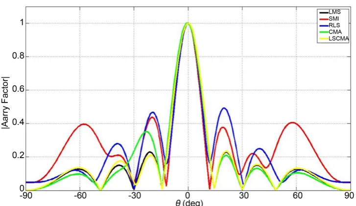
In order to investigate the performances of the above mentioned smart an-tenna algorithms namely LMS, SMI, RLS, CMA and LSCMA we design a linear antenna array consisting of 8-elements. The antenna elements are separated by a distance of λ/2. The desired signal is arrived at θ = 0˚ and the interfering signal is arrived at θ = −30˚. We assume the desired signal is purely sinusoidal with pe-riod 1 mS. The radiation patterns for these algorithms are illustrated in Figure 11. The antenna array is operated in a noisy environment. We assume the noise is Gaussian with mean 0 and standard deviation 1. It is depicted in the figure that all the investigated algorithms generate a maximum radiation patter in the de-sired direction (i.e., θ = 0˚). It is also depicted that all the algorithms generate null at the interfering signal (i.e., θ = −30˚) except CMA algorithm. The CMA algorithm only attenuates the signal, but it fails to nullify the signal. In terms of side lobe amplitude, the LMS and LSCMA algorithm performs better compared to other three algorithms. The RLS algorithm produces maximum side lobe. The side lobes attenuate very quickly except SMI algorithm. The side lobe reduces to 0.1 for the SMI algorithm, but the same increases to 0.4 again. Although the LMS and LSCMA show similar performance in terms of side lobe minimization, the LSCMA should be used in the ad hoc networks because of its rapid convergence property compared to its LMS counterpart.
In order to investigate the performances of investigated algorithms under va-rying noise condition we conduct the similar experiment as mentioned above. But, we set the noise mean to 2 and standard deviation 1. The generated radia-tion patterns by the algorithms are shown in Figure 12. It is depicted in the fig-ure that all smart antenna algorithms except RLS produce maximum radiation along the desired direction (i.e., θ = 0˚). In terms of side lobe attenuation CMA algorithm outperforms other algorithms. The performance of LSCMA is also very much similar to CMA algorithms. But, CMA outperforms LSCMA.
5. Conclusion
Figure 11. Comparison with noise mean 0 and standard deviation 1.
Figure 12. Comparison with noise mean 2 and standard deviation 1.
noise condition. But, CMA algorithm outperforms LSCMA algorithm under noisier conditions.
References
[1] Goldsmith, A.J. and Wicker, S.B. (2002) Design Challenges for Energy-Constrained Ad Hoc Wireless Network. IEEE Wireless Communication, 9, 8-27.
https://doi.org/10.1109/MWC.2002.1028874
[2] Bellofiore, S., Foutz, J., Govinfarajula, R., Bachceci, I., Balanis, C.A., Spanais, A.S., Capone, J.M. and Duman, T.M. (2002) Smart Antenna System Analysis, Integra-tion, and Performance for Mobile Ad Hoc Networks (MANETs). IEEE Transaction
on Antennas and Propagation, 50, 571-581.
https://doi.org/10.1109/TAP.2002.1011222
[3] Radhakrishnan, R., Lai, D., Caffery, J. and Agrawal, D.P. (2002) Performance Com-parison of Smart Antenna Techniques for Spatial Multiplexing in Ad Hoc Net-works. Proceedings of the 5th International Symposium on Wireless Personal
Mul-timedia Communications, 1, 168-171.
[4] Nasipuri, A., Ye, S., You, J. and Hiromoto, R.E. (2000) A MAC Protocol for Mobile Ad Hoc Networks Using Directional Antennas. Proceedings of IEEE Wireless
Communication and Networking Conference, Chicago, IL, Vol. 3, 1214-1219.
[5] Takai, M., Martin, J., Bagrodia, R. and Ren, A. (2002) Directional Virtual Carrier Sensing for Directional Antennas in Mobile Ad Hoc Networks. Proceedings of the
3rd ACM International Symposium on Mobile Ad Hoc Networking & Computing,
Lausanne, June 2002, 183-193. https://doi.org/10.1145/513800.513823
[6] Roychoudhury, R., Yang, X., Ramanathan, R. and Vaidya, N. (2002) Medium Access Controlin Ad Hoc Networks Using Directional Antenna. Proceedings of the
8th Annual International Conference on Mobile Computing and Networking,
At-lanta, Georgia, 23-28 September 2002, 59-70.
[7] Bao, L. and Garcia-Luna-Aceves, J.J. (2002) Transmission Scheduling in Ad Hoc Networks with Directional Antenna. Proceedings of the 8th Annual International
Conference on Mobile Computing and Networking, Atlanta, Georgia, 23-26
Sep-tember 2002, 11 p.
[8] Spyropoulos, A. and Raghabendra, C.S. (2003) Capacity Bounds for Ad hoc Net-work using Directional Antennas. Proceedings of the IEEE International
Confe-rence on Communication, Anchorage, Alaska, May 2003, 348-352.
[9] Ramanthan, R. (2001) On the Performance of Beamforming Antennas in Ad Hoc Networks. Proceedings of the ACM Symposium on Mobile Ad Hoc Networking &
Computing, Long Beach, CA, 4-5 October 2001, 95-105.
https://doi.org/10.1145/501416.501430
[10] Spyropoulos, A. and Raghavendra, C.S. (2003) Energy Efficient Communications in Ad Hoc Networks Using Directional Antennas. Proceedings of the 22nd Annual
Joint Conference of the IEEE Computer and Communications Societies, San
Fran-cisco, CA, March-April, 2003, Vol. 1, 220-228.
[11] Nasipuri, A., Li, K. and Sappidi, U.R. (2002) Power Consumption and Throughput in Mobile Ad Hoc Networks Using Directional Antennas. Proceedings of the 11th
Conference on Computer Communication and Networks, Miami, FL, October
2002, 620-626.
[12] Winters, J.H. (2006) Smart Antenna Techniques and Their Applications to Wireless Ad Hoc Networks. IEEE Wireless Communication, 13, 77-83.
[13] Belanis, C.A. (2005) Antenna Theory: Design and Analysis. 3rd Edition, John Wiley and Sons, NJ, 826-837.
[14] Gross, F. (2005) Smart Antennas for Wireless Communications with Matlab. 2nd Edition, McGraw Hill, New York, 227-251.
[15] Monzingo, R. and Miller, T. (1980) Introduction to Adaptive Arrays. Wiley Inters-cience, John Wiley and Sons, New York.
[16] Widrow, B., Mantey, P., Griffith, L., et al. (1967) Adaptive Antenna System.
Pro-ceedings of IEEE, 55, 2143-2159.
[17] Godara, L. (2004) Smart Antennas. CRC Press, Boca Raton, FL.
https://doi.org/10.1201/9780203496770
[18] Godara, D.N. (1980) Self-Recovering Equalization and Carrier Tracking in Two Dimensional Data Communication Systems. IEEE Transactions on
Communica-tions, 28, 1867-1875.
[19] Rong, Z. (1996) Simulation of Adaptive Algorithm for CDMA Systems. Master’s Thesis, Mobile and Portable Radio Research Group, Virginia Tech, Blacksburg, VA.
Submit or recommend next manuscript to SCIRP and we will provide best service for you:
Accepting pre-submission inquiries through Email, Facebook, LinkedIn, Twitter, etc. A wide selection of journals (inclusive of 9 subjects, more than 200 journals)
Providing 24-hour high-quality service User-friendly online submission system Fair and swift peer-review system
Efficient typesetting and proofreading procedure
Display of the result of downloads and visits, as well as the number of cited articles Maximum dissemination of your research work
Submit your manuscript at: http://papersubmission.scirp.org/
![Figure 1. Capacity improvement of ad hoc network with smart antenna [2].](https://thumb-us.123doks.com/thumbv2/123dok_us/7785505.723385/2.595.211.537.559.712/figure-capacity-improvement-ad-hoc-network-smart-antenna.webp)