HONEYWELL CONFIDENTIAL
AND PROPRIETARY
This document and the information contained herein are confidential to and the property of Honeywell Information Systems Inc. and are made available only to Honeywell employees for the sole purpose of con-ducting Honeywell's business. This document, any copy thereof and the information contained herein shall be maintained in strictest confi-dence; shall not be copied in whole orin part except as authorized by the em ployee' s manager; and shall not be disclosed or distributed (a) to persons who are not Honeywell employees, or (b) to Honeywell em ployees for whom such information is not necessary in connec-tion with their assigned responsibilities. Upon request, orwhen the em ployee in possession of this document no longer has need for the document for the authorized Honeywell purpose, this documentand any copies thereof shall be returned t the employe's manager.
There shall be no exceptions to the terms and conditions set forth herein except as authorized in writing by the responsible Honeywell Vice President.
DPS
8/C
CP-6
DPS
SIC
CONFIGURATION GUIDE
HGNEYWELL CONFIDENTIAL & PROPRIETARY
:£: f • •
This document and the information contained herein are confidential to and the property of Honeywell Information Systems Inc. and are made available only to Honeywell employees for the sole purpose of conducting Honeywell's business. This document, any copy thereof and the information contained herein shall be maintained in strictest confidence; shall not be copied in whole or in part except as authorized by the employee's manager; and shall not be disclosed or distributed (a) to persons who are not Honeywell employees, or (b) to Honeywell employees for whom such information is not necessary in connection with their assigned responsibilities. Upon request, or when the employee in possession of this docu-ment no longer has need for the docudocu-ment for the authorized Honeywell purpose, this document and any copies thereof shall be returned to the employee's manager. There shall be no exceptions to the terms and conditions set forth herein except as authorized in writing by the responsible Honeywell Vice President.
ORDER NUMBER
DP37-02 May 1983
CP-6
DPS 8/C Configuration Guide
PREFACE
This guide at·tempts to provide nearly complete freestanding information for configuring any portion of a CP-6 DPS 8/C system. Included in this outline are only the DPS 8/C systems announced in March 1981 and updated by subsequent
announcements. In addition, this material covers all peripherals which are the most current for DPS 8/C and the Level 66/DPS Band C systems. To configure CP-6 central systems and front end processors for other than DPS 8/C systems
use the CP-6 Configuration Guide, Revision 6, February 23, 1981, available from the CP-6 Program Office.
The guide is constructed to be as self-teaching as possible and to provide for configuring both initial system orders and subsequent add-ons.
Material in this outline dealing with DPS 8/C central systems consists
mainly of a set of charts and brief summaries which are designed to be largely self-explanatory. By following the appropriate flowcharts and tables you will be able to configure any initial system order or add-on order accurately.
This material is divided into gross functional sections. Be sure to read the Table of Contents in full before using the configuration material. The table will show you the pattern of approach used in configuring.
Section 1 summarizes key general rules and policies which govern configura-tion of DPS 8/C systems. Before doing any configuring you should always review
Section 1.
Section 2 provides master flowcharts which identify the sequence and compo-nents to be considered in configuring. Detach the pertinent flowchart(s) and keep it in view while you use it to access other portions of this material in order to configure easily, completely, and accurately. The flowchart has chapter references to other sections for detailed information on configuration of the components at each level of the flowchart.
Section 3 contains overview configurators to give you the perspectives for complete systems.
Section 4 covers the configuring of central systems and memory sizes.
Included in this section are all marketing identifiers for all central systems.
CP-6
DPS 8/C Configuration Guide
Section 5 covers the configuring of the components needed within each IOM. Th~se components relate to physical and logical IOM channels for peripheral subsystems and IOM aggregate load considerations.
Sections 6 through 9 cover the configuring of unit record, magnetic tape, mass store, and console subsystems.
Section 10 introduces you to some generic terms and concepts related to data communications and front end processors (FEPs).
Section 11 covers the configuration of the DN8/C FEP.
Section 12 deals with manually controlled peripheral switches.
Section 13 includes the motor-generator sets and circumstances dealing with their use.
Section 14 covers CP-6 software products.
Site preparation information for DPS 8/C may be found in the Site Preparation Manual for DPS 8/20, 8/44 (Order Number DL64) and in the DPS 8 (Freestanding) Site Preparation Manual for DPS 8/52/62/70 (Order Number DN01). Site preparation information for configurable DPS 6 peripheral equipment may be found in the DPS 6 Systems Site Preparation Manual (Order Number CP77-00).
ill
CONTENTS
Section 1.
Section 2.
Section 3.
Section 4.
Section 5.
Peripheral and Communications Subsystems per CP-6 System
Lower Speed Subsystems Higher Speed Peripherals
Master Flowcharts for DPS 8/C Configuring
DPS 8/47C/49C Systems
DPS 8/52C/62C/70C Systems
Configura tor Overview DPS 8/47C/49C/20C/44C
DPS 8/52C/62C/70C
Central System Configuring
Ordering the Central System (CPS) DPS 8/47C/49C CPS Identifiers
DPS 8/52C/62C/70CCPS Identifiers
Ordering Extra CPUs, SCUs, IOMs for DPS 8/47C/49C
Ordering Extra CPUs, SCUs, IOMs for DPS 8/52C/62C/70C
DPS 8/C Memory Configura tors
Computing Memory Requirements for DPS 8/C
Memory Interleaving Aspects
Configuration Examples for Initial Orders and Additions
Configuring Within Any IOM Base IOM and Extra IOMs
Physical Channels and Logic Boards
Assigning Logical Channels to Physical IOM Channels Subsystems Allowing Multiple Logical Channels Per Physical Channel
Unit Record Processor Subsystems Magnetic Tape Processor Subsystems Disk Subsystems
Subsystems Allowing Only a Single Logical Channel Per Physical Channel
FEPs Consoles
IOM Aggregate Load Considerations IOM Configuring - An Example
CONTENTS (Cont.)
Section 6.
Section 7.
Section 8.
Section 9.
Section 10.
Section 11.
Unit Record Subsystems
Configuring the DPS 8 Unit Record Processor (URP) Subsystems
Example of DPS 8 URP Configuring
Configuring Supported DPS 6 Unit Record Equipment Example of DPS 6 Unit Record Configuring
Magnetic Tape Subsystems
Configuring Magnetic Tape Subsystems
Magnetic Tape Subsystem Configuring Example
Mass Storage Subsystems
Configuring Mass Storage Subsystems
Configurator for MSP8000 Subsystems (Single-Channel 1x1b) for DPS 8/47C/49C Only
Configurator for MSP8002 Subsystem (Dual-Channel 2x16) for DPS 8/47C/49C Only
Configurator for MSP0611 Freestanding Subsystem (Single-Channel 1x16) for any DPS 8/C Subsystem Configurator for MSP0612 Freestanding Subsystem
(2x16, 2x30, 2x32) for any DPS 8/C Subsystem Configuring Example for Mass Storage
Configuring Consoles
Configuration Rules for IO~Connected Console Subsystem for DPS 8/C Systems
Console Subsystem (CSU6601)
Auxiliary Console Adapter (CSF6602) Console Switch Feature (CSF6606)
Generics of Data Communications - Front End Processors (FEPs)
Configuring DATANET 8/C Front End Processor (FEP) Required Configuration Components
Networking Considerations Configuring the DATANET 8/C
DN 8/C FEP-Related Marketing Identifiers and Their Functions
Supported Terminals Async Profiles 3270 Profiles RBT Profiles
v
HONEYWELL CONFIDENTIAL AND PROPRIETARY
CONTENTS (Cont.)
Section 11. Cont.
Section 12.
Section 13.
Section 14.
Appendix A.
FEP Throughput Calculations and CI Board Packaging Tables
CIBs
Physical Board Size Throughput Load Factor
Protocol Type
TP Forms Processing Unit Record Devices Remote FEPs
Determination of Remote FEP Link Speed DATANET 8/C Configuration Examples
Example #1 Example #2 Example 13
Example #4
Peripheral Switches
Configuring Manual Peripheral Switch Subsystems Examples of U~e of Manual Peripheral Switches
Example 1 Example 2 Example 3
Configuring Motor-Generator and Control Sets
Software
Checklist Configura tor
Page
11-16
11-16 11-16 11-18 11-18 11-28 11-33 11-34 11-35
11-36 11-38 11-40 11-43
12-1
12-3 12-4 12-5
13-1
CONTENTS (Cont.)
FIGURES
Figure 4-1. Figure 4-2. Figure 4-3. Figure 4-4.
Figure 5-1. Figure 5-2.
Figure 6-1. Figure 6-2. Figure 6-3. Figure 6-4. Figure 6-5. Figure 6-6.
Figure 7-1. Figure 7-2.
Figure B-1. Figure B-2. Figure B-3. Figure B-4.
Figure 9-1. Figure 9-2.
Figure 10-1.
Figure 11-1 • Figure 11-2. Figure 11-3. Figure 11-4. Figure 11-5. Figure 11-6. Figure 11-7. Figure 11-B. Figure 11-9. Figure 11-10. Figure 11-11. Figure 11-12. Figure 11-13.
Figure 11-14.
Figure 12-1. Figure 12-2. Figure 12-3. Figure 12-4. Figure 12-5.
DPS BIC Central System Components DPS BI20C/44C Memory Configurator
DPS B/47C/49C Sample Memory Configurator DPS B/52C/62C/70C Memory Configurator
Physical Channel Configurator
Physical Channel and Logical Channel Concepts
Configurator for URP0600lBOOO Configurator for URP in MFPBOO 1
Configurator for URAs and Associated Unit Record Devices Configurators for URPB011/B0121B013
Configurator for PRU0901/1201
Configurator for DPS 6 Unit Record Equipment
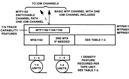
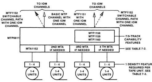
Single-Channel MTP Configurator Dual-Channel MTP Configurator
MSPBOOO Block Diagram MSPB002 Block Diagram MSP0611 Block Diagram MSP0612 Block Diagram
CSU6601 Block Diagram CSF6602 Block Diagram
Typical Front End Processor Components
DATANET BIC Block Diagram
DATANET BIC Memory Configurability CI Physical Board Sizes
ASYNC Input Performance
ASYNC Output Performance, Non-Transparent ASYNC Output Performance, Transparent
HASP, 27BO, 37BO Input & Output Performance 3270 Input Performance
3270 Output Performance
FEP TP Forms Performance, Systems Input FEP TP Forms Performance, Systems Output URP Performance
Remote FEP Performance - Input
&
Output, No Transaction ProcessingDATANET BIC Configuration Example 14
PSU0200 Configurator PSU0201 Configurator
Switching Between Two Device Processors
Switching Between Two Physical IOM PSI Channels Switching Between Two Device Processors and Between
Two IOM Physical Channels
vii
HONEYWELL CONFIDENTIAL AND PROPRIETARY
CONTENTS (Cont.)
Figure A-1 Figure A-2
Figure A-3 Figure A-4 Figure A-5 Figure A-6 Figure A-7 Figure A-8 Figure A-9 Figure A-10
TABLES
Table 5-1. Table 5-2. Table 5-3.
Table 6-1.
Table 7-1. Table 7-2. Table 7-3.
Table 8-1. Table 8-2. Table 8-3. Table 8-4.
Table 11-1. Table 11-2. Table 11-3.
DPS 8/47C/49C Central Systems and Major Subsystems DPS 8/52C/62C/70C Central Systems and Major
Subsystems
IO~Connected Console Communications Subsystem Magnetic Tape Subsystem Mass Storage Subsystem Unit Record Subsystem DPS 6 Peripherals Peripheral Switches
Motor Generators/Capacitor Ridethroughs
Configurator for Logical Channel Assignments Estimated Device Bandwidths
Solution to 10M Configuration Example
DPS 8 Unit Record Devices
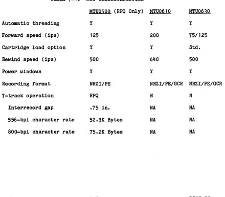
MTU Characteristics
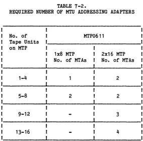
ReqUired Number of MTU Addressing Adapters MTU Density Features
MSP8000 Configuration MSP8002 Configuration MSP0611 Configuration MSP0612 Configuration
DATANET 8/C Board Slot Assignments CIB Throughput CapaCity
DATANET 8/C Channel Interface Physical Board Sizes
SECTION 1
Peripheral and Communications Subsystems Per CP-6 System
LOWER SPEED SUBSYSTEMS
Min Max
Card reader or 0 As needed (See Note 2) card reader/punch
Card punch 0 As needed (See Note 2)
Printer 0 As needed (See Note 2)
FEP 1 (See Note 1 )
(See Note 3)
Console (IOM-connected) 4 (See Note 4)
Notes;
1. MaXimum of 12 local FEP's per system. Maximum of 4 remote FEP's per local FEP. Maximum of 16 FEP's per system (including both
lo~al and remote FEPs). See Section 11.
2·. Maximum of 2 unit record devices on URP80 12/8013. Maximum of 4 unit record devices on URP8011 and on URP in MFP8001 for DPS 8/47C/49C. Maximum of 8 devices on other URPs. Maximum of 6 unit record devices on each Front End Processor.
3. One Front End Processor (FEP) included with CPS81XX. Every FEP reqUires a minimum of one CIB and one async CI, neither included in base price. One additional CIB and one sync CI (Bell 201C modem or equivalent) per CP-6 system (neither included in bas~
price) is strongly recommended for a sync line to interface to the automated system for software support and distribution of patches.
4. FEP-connected consoles may be added as needed.
1-1 DP37-02
HIGHER SPEED PERIPHERALS
Min Max
Magnetic tapes 1 (See Note 1) As needed (See Note 2)
Disk storage 157 M Bytes
(See Note 3) As needed (See Note 4)
Notes;
1. One tape unit is normally used for the initial system boot.
2. The maximum isB tape units on single-channel MTP, 16 on dual-channel MTP. "Maximum of
B
tapes on MFPB001.3. Needed for CP-6 Operating System, support and temporary files.
SECTION 2
Master Flowcharts for DPS SIC Configuring
DPS 8/47C/49C SYSTEMS
DETERMINE foIJDfL SIZE DESIRED
ORDER BASIC CPS NO. CENTRAL SYSTEM
~4
<>6
~R;R EX~
;u!
jORiR ~RP-;0
'lI SCU. 10M ~ OPS8 UR DEVICES
L
AS DESIRED_--_J
I I_-_-.J
IF DESIRED IORDER COHSOLE(S)
11
ORDER
CIB(S); CI(S); EXTRA FEP(S)
AS DESlRED
QtJ __ ,
I ORDER 'fo«lTOR-GENERATOR :
l~T~ ~DE~
J
<>
14r - -
- jI ORDER
I OPTIONAL
L _
S~~R:"J
CONFIGURATOR
ORDER MTP
AND HTUs
CHECK PERIPHERALS MIN/MAX TABLES
8
ORDER MSP AND MSUs
~~--l ~4
_ _ _I ORDER DPS 6 I ORDER ott
1
I UR DEVICES
~MEMORY
INCREMENTS,'L IF DESIRED.J
L
AS NEEDED----
--r-.J
05
<>
14CONFIGURE WITH 10M(S)
RECHECK FOR ACCURACY 2-1
<>
ORDER REQUIRED SOFTWARE LEGEND REQUIRED OPTIONAl REFERS TO SECTION CONTAINING DE-TAILED INFORMATIONHONEYWELL CONFIDENTIAL AND PROPRIETARY
DPS 8/52C/62C/7QC SYSTEMS
ORDER CONSOLE(S)
DETERMINE MODEL SIZE DESIRED
ORDER BAS I C CENTRAL SYSTEM CPS NO.
3 SEE DPS 8/52C/ 62C/70C OVERVIEW
CONF I GURATDR
0'4
IO;E;-EX;; ..,
CPu&, Sr.lIs. rOMs I
CHECk PERIPHERALS 'UN/MAX TABLES
, AS DESIRED I
_---.-~J-~
i>6J_.., <>7
J ORDER DPS H URP, AND UR DEVICES
I
_-_-.J
IF REQUI REO I11
ORDER
... -3MCIB(S); Cl (S); EXTRA FI!P(S) AS DESIRED
ORDER MOTOR GEN. SET(S)/CAPACITOR
RIDE lliROUGHS
0.,L4
r - - 1
, . ORDER
I OPTIONAL
l_
SO~n.~E_J
ORD[R
fITP AND MTUs
8
ORDER, H5P AND
MSUs
~~--T
~'---I ORDER DP5 6 UR·. I ORDER C...
l
I " DEVICES
~HEI10RY ~NCREHENTSI
L~~E~~~ L_A~EEDE~..J
5 CONFIGURE WITHIN 1(14(5 ) RECHECK FOR
ACCURACY
o
ORDER REQUIRED SOfTWARE LEGEND REQUIRED OPTIONAL
SECTION 3
Configurator Overview
prs
BI47C/4gC/20C/44C,
.•..•...
: Motor Central Shared Cabinet : Generator
: Set
•...
URP0600
1 x 8
I
MTP0611
1 x 8
MTP0611 MTF1151 2 x 16
... l ...
: Auxiliary : r---'--.L·C;;.;S~U 6602 : • CSU6601 •••••••• 1 required ... .. • : CSF6601 :
.
.
.
.
I . . . ..
Required Per System 1 MT Subsystem 1 MS Subsystem 1 CIB & 1 async line 1 CSU6601 console
1 212A modem & comm. line
OPS 8/20C, 8/44C Options
CPU
ON 8C OCU8011
Extra SCU - MXC8003 Maximum SCU Upgrade - MXK8007 }
Extra 10M _ MXU8003 1 each (3 & 4 CPU configurations available via RPQ after s stem up rade with CPK8366)
(See p. 3-2 for notes)
•....•....•..•..••
,
Upgrade Kit :(see note) :
••.•••••...••
Power Supply
To 16, 64 or 128 lines
3-1
10M
Communication Subsystem with Host Connect
•••• 1 ••••••••••• 1 •••
: URP8011 : : 1 x 4 :
.
....•••••..•...•
.
... .1 ••••••••••
: URP8012/8013 :
: 1 x 2 :
~
.•...•...•...
~OPS 8/47C, 8/49C Options
- CPS8119, OPS 8/47C, std.
12 MB memory - CPS8121,
OPS 8/49C, std.
16 MB memory
Extra CPU CPU8119 for OPS 8/47C Max 1 CPU8121 for OPS 8/49C Max 3 SCU Upgrade MXK8007 2-5 port expansion
MXK8009 5-8 port expansion Extra SCU MXC8003 (5 port) Max 1
Extra 10M MXU8003 Max 1
Tandem Systems use
1 RSF8001- Redundant System Facility 2 CPS81 XX-Central Systems
2 MXKB007 - SCU Expansions 2 CSU6601-Consoles
DP37-02
Notes: Performance upgrade Kit DPS 8/20C (CPS8114) to 8/44C (CPS8116) is CPK8113.
- CPU upgrade: Cpu8114 to CPU8116 is CPK8119.
- Performance upgrade Kit DPS 8/44C (CPS8116) to 8/49C (CPS8121) is CPK8366.
- Performance upgrade Kit DPS 8/44CD (CPS8117) to 8/49C (CPS8121 and CPU8121) is CPK8367.
- CPU upgrade: cpu8116 to CPU8121 is CPK8368.
Central System upgrade DPS 8/47C (CPS8119) to 8/49C (CPS8121) is CPK8362.
DPS 8/52C/62C/70C
,
...•...•..••...•••..•...•....•...•...
,
·
·
Capacitor Ridethrough PSS8000 Motor Generator Set(s) Battery Backup PSS8002 (1 perSCU) or UPS
I
URP06001 x 8
I
~ • • • • • • • • • • • • • • • • • • J
: Upgrade Kits - : : see note :
~
...•..•...•
_.J ••
.1~~••
l..
: URP8011 :
: 1 x 4 :
...
·
·
·
·
·
·
·
·
·
·
- DPS 8/52C, CPS 8173,
Std. 16 MB Memory - DPS 8/62C, CPS8174,
Std. 16 MB Memory - DPS 8/70C, CPS8178,
Std. 16 MB Memory
•••••••• L... ~~ ... ~ ... ~ ... ~~~~~
MTP0611 1 x 8
: URP8012 : ~ Upgrade DPS 8/50C I~
L.~.~{;.~~.~
..
l
~
!O
!!~~ ~~~
1?!
~
... 1
~~~~d~CD~~K~~~~
----~~.--.---
r-upgr;;eDPS8~cl
MTP0611 MTF1151 2 x 16
MSP0611 1 x 16
..••..• 1
... .
I
Auxiliaryi
_--"'----;...,. CSU 6602 :CSU6601 ~
... .
1 required •••••••••••••• • CSF6601 :
• • •
•..•...•.•
DN 8C DCU8011
'--______ ... To 16, 64 or 128 lines
Required per System
1 MT subsystem 1 MS subsystem 1 CSU6601
1 CIB and 1 async line
1 212A modem and comm. line 1 motor generator or PSS8000 fOr}
each CPU/10M
1 battery backup on each SCU
or UPS
Commumcatl~ns Subsystem with
I
.. to 8/70C CPK8172 _ _ _ _ _ _ 1 ~host connect
rs····s··
···12
x 30 : MSP MSP : 2 x 32.
.
: :2x16
r •••••••••••••• ~ MSP0612
DPS 8/52C, 8/62C, 8/70C Options:
Extra CPU CPU8173 for DPS 8/52C Max 1 CPU8174 for DPS 8/62C Max 1 CPU8178 for DPS 8/70C Max 5* Extra SCU MXC8002
Max 3·* each Extra 10M MXU8002
cross-barring included Tandem Systems use 1 RSF8002 and 2
CPS8173/8174/8178
* Total CPUs and IOMs
=
8 or less~ CPU Upgrades: CPU8170 to CPU8173 is CPK8177j CPU8173 to CPU8174 is CPK8174j CPU8174 to CPU8178 is CPK8178
3-3 DP37-02
SECTION
4
Central System Configuring
ORDERING THE CENTRAL SYSTEM (CPS)
This is the configuration which is the heart of each initial order. It is obtained by use of the CPS marketing identifier for the model you want to order. The base CPS identifier is the first identifier that you write on your initial order. All additions at the time of the initial order or after the system has been installed are made to the base CPS system. The base CPS system is also known as the base system, basic system, or base mainframe.
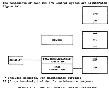
The components of each DPS SIC Central System are illustrated in Fig ure
4
-
1.
CPU
~.
I
L....J
MEMORY scu
1"""""1
I
DATA COMMUNICATIONS· L-J
CONSOLE·· MXA
SUBSYSTEM
HOST 10M
CONNECTION
• Includes diskette, for maintenance purposes
•• 30 cp~ terminal, included for maintenance purposes
Figure 4-1. DPS SIC Central System Components
Each CPS identifier gives you a complete central system as shown:
~ CPU and ~ SCU, a base quantity of memory, one lQM, plus ~
Central Processor Addressing feature or port (CPA) in the CPU and ~
10M Addressing feature or port (HIA) in the 10M, ~ Data Communica-tions Subsystem, including one Host Connection, one CommunicaCommunica-tions Subsystem connected, 30 cps Console and one diskette (the console and diskette are included for maintenance purposes). Components in the central system do not have individual identifiers.
DPS S/47C/49C central systems may be connected together via the Redundant Systems Facility (RSFS001), provided both systems have upgraded to a 5 port SCU with the SCU Expansion (HXKS007). DPS S/52C/62C/70C central systems may be connected together via the Redundant Systems Facility (RSFS002).
4-1 DP37-02
[image:19.623.143.526.222.532.2]DPS 8/47C/4qC CPS Identifiers
o CPS8119 for DPS 8/47C
o CPK8362 Upgrade Kit from CPS8119 to CPS8121
o CPS8121 for DPS 8/49C
Each CPS identifier includes:
o Central system cabinet (CSC).
o CPU, SCU, 10M - 1 each, with connecting cables and addressing features. 10M includes 20 logic board slots for physical 1/0
channels.
o Memory: 12M bytes on the DPS 8/47C (expandable to 32M bytes in 2 or 4M byte increments - requires MXC8003, additional 5 port SCU, beyond 16M bytes). 16M bytes on the DPS 8/49C (expandable to 32M bytes in 2 or 4M byte increments--requires MXC8003, additional 5 port SCU).
o Power supply for all components within the central system cabinet.
o Space for one MSP8000 or one dual channel MSP8002.
o Space for one MFP8001 or one MTP8001 or one URP8000. The peripheral processors themselves are not included in CPS8119/8121 identifiers.
o All items above contained in the central system cabinet.
o One freestanding Data Communications subsystem with one Host
Connection, one Communications Subsystem connected, 30 cps Console and one diskette (the console and diskette are included for main-tenance purposes).
DPS BI52C/62C/70C CPS Identifiers
0 CPS8173 for DPS 8/52C
0 CPK8176 Upgrade Kit from CPS8170 (DPS 8/50C) to CPS8173 (DPS 8/52C)
0 CPK8164 Upgrade Kit from CPS8173 to CPS8174
0 CPS8174 for DPS 8/62C
0 CPK8172 Upgrade Kit from CPS8174 to CPS8178
0 CPS8178 for DPS 8/70C
Each CPS identifier includes:
o One CPU and its power supply.
o 16M bytes main memory. All are expandable to 64M bytes. MXC8002 required for each 16M bytes or fraction thereof above initial 16M bytes.
o One IOM with own power supply and inclusion of 36 logical board slots for physical I/O channels. Capacity for 18 more board slots for I/O channels via MXF8005 Channel Expansion option.
o CPU, SCU, IOM and Data Communications Subsystem (which also includes one Host Connection, one Communications Subsystem connected, 30 cps Console and one diskette). Connecting cables and addressing features are included in CPS iden~~fier.
o Requires 1) MG and one PSS8002 Battery Backup on each SCU (neither included in CPS), or 2) one PSS8000 Capacitor Ride-Through for each CPU/IOM and one PSsa002 Battery Backup on each SCU, or 3)
ups.
o Requires one standard dial up line and one 1200 baud asynchronous modem (must be Bell 212A, or Vadic Triple Modem (3451P, 3451S), or Rixon T212A, or equivalent) for use with the diagnostic processing functions. Neither the line nor the modem is included in the CPS.
4-3 DP37-02
ORDERING EXTRA CPUs, SCUs, IOMs FOR DPS 8/47C/4gc
One additional SCU, 10M and/or CPU can be ordered initially, or later as additions on DPS 8/47C. One additional SCU and 10M and up to three additional CPUs can be ordered initially, or later as additions on DPS 8/49C.
o Maximum of two SCUs, two IOMs and two CPUs per DPS 8/47C System.
o Maximum of two SCUs, two IOMs and four CPUs per DPS 8/49C System.
o Marketing identifiers
- SCU: MXK8007 MXK8009 MXC8003
10M: MXU8003
- CPU: CPK8113
CPK8119
CPU8119 CPU8121
CPK8362
CPK8365
CPK8366
CPK8367
CPK8368
- Tandem System: RSF8001
SCU Port Expansion (2 - 5 Port) SCU Port Expansion (5 - 8 Port) Additional (5 Port) SCU
Additional 10M (requires MXK8007)
Performance increase DPS 8/20C (CPS8114) to DPS 8/44C (CPS8116) - requires CPK8119 if system includes CPU8114; requires SFS6130, if installed, be replaced with SFS6135. CPU8114 to CPU8116 performance increase
(requires CPK8113).
Additional DPS 8/47C CPU (requires MXK8007). Additional DPS 8/49C CPU (requires MXK8007,
requires MXK8009 and 2nd CSU6601/6602 for 3rd CPU on a system).
Central System increase DPS 8/47C (CPS8119) to DPS 8/49C (CPS8121) - requires CPK8365 if system includes CPU8119; requires SFS6135, if installed, be replaced with SFS6145.
CPU8119 to CPU8121 performance increase (requires CPK8362).
Performance increase DPS 8/44C (CPS8116) to performance of DPS 8/49C (CPS8121) - requires CPK8368 if system includes CPU8116; requires SFS6135, if installed, be replaced with SFS6145. Performance increase DPS 8/44CD (CPS8117) to
performance of DPS 8/49C (CPS8121 and CPU8121); requires SFS6135, if installed, be replaced with SFS6145.
cpu8116 to CPQ8121 performance increase (requires CPK8366).
Redundant System Facility for CPS8119/8121 -requires MXK8007 installed in each SCQ.
ORDERING EXTRA CPUs, SCUs, IOMs FOR DPS 8/52C/62C/70C
Up to 3 more SCUs and/or IOMs can be ordered initially, or later as
additions on DPS 8/52C/62C/70C. One additional CPU may be ordered for DPS 8/52C/62C. Up to 5 more CPUs can be ordered initially, or later as
additions on DPS 8/70C, provided that the combined total of CPUs and IOMs are less than or equal to 8.
o Maximum of four SCUs, IOMs per DPS 8/52C/62C/70C system. Maximum of two CPUs on DPS 8/52C/62C. Maximum of six CPUs on DPS 8/70C, so long as the combined total of CPUs plus IOMs are less than or equal to eight.
o Marketing identifiers
SCU: MXC8002
10M: MXU8002 MXF8005
CPU: CPU8173 CPU8174 CPU8178 CPK8176
CPK8164
CPK8172
CPK8177
CPK8174
CPK8178
Tandem System: RSF8002
Additional SCU
Additional 10M
10M Expansion (36 to 54 slots)
Additional DPS 8/52C CPU Additional DPS 8/62C CPU Additional DPS 8/70C CPU
Performance increase, DPS 8/50C (CPS8170) to DPS 8/52C (CPS8173) - requires CPK8177
if system includes CPU8170; requires SFS6140, if installed, be replaced with SFS6145.
Performance increase, DPS 8/52C (CPS8173) to DPS 8/62C (CPS8174) - requires CPK8174
if system includes CPU8173; requires SFS6145,
if installed, be replaced with SFS6150. Performance increase, DPS 8/62C (CPS8174)
to DPS 8/70C (CPS8178) - requires CPK8178
if system includes CPU8174; requires SFS6150,
if installed, be replaced with SFS6155. CPU8170 to CPU8173 performance increase
(requires CPK8176).
CPU8173 to CPU8174 performance increase (requires CPK8164).
CPU8174 to CPU8178 performance increase (requires CPK8172).
Redundant System Facility for CPS8173/8174/8178.
o All necessary connecting cables and addressing features are automa-tically included. Each CPU and each 10M is cross-barred to each SCU by Customer Services at the site. You must supply cable lengths.
4-5 DP37-02
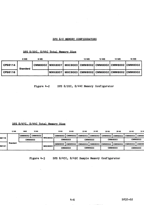
DPS BIC MEMORY CONFIGURATORS
Drs
BI20C, B/44C Total Memory Size6MB 8MB 10 MB 12 MB 14 MB 16 MB
CPS8114 CMM8002 MXK8007 MXC8003 CMM8002 CMM8002 CMM8002 CMM8002
Standard
CPS8116 MXK8007 MXC8003 CMM8002 CMM8002 CMM8002 CMM8002
Figure 4-2 DPS B/20C, B/44C Memory Configurator
Drs
B/47C, B/49C Total Memory Size12MB 14MB 16MB 18MB 20 M8 22 MB 24 MB 26 MB 28 MB 30 MB 32 MB
CPS8119
CMM80021 CMM8002
MXC8003
CMM80021 CMM8002 CMM8002lCMM8002 CMM80021 CMM8002 CMM8002 J CMM8002
CMM8003 CMM8003 CMM8003 CMM8003 CMM8003
Standard
CMM8002
I
CMM8002 CMM80021 CMM8002 CMM80021 CMM8002 CMM80021 CMM8002CPS8121 MXC8003
CMM8003 CMM8003 CMM8003 CMM8003
[image:24.617.55.553.51.758.2])
DPS 8/soC. 8/52C. 8/62C. 8/70C Total Memory Size
111.48 181.48 201.48 241.48 2111.48 211.41 301.41 32 1.48
CI'II170/1113/,11.,.,7. "'8ooZ- 8tanct.rd PS8800Z- MXC8002 CMM8oao CMM8020 CMM80Z0 CMMB020 CMM80Z0 CMM8020 CMMOOZO CMM8020 Dl'l1i1OC. IIIZC. IIIZC. 1170e
34MB J6 MB 3B.MJl 40 MB 4lMB 44 MB 411.48 411.41
eN.nOI.IU/.11.,.,7. PS88ooa- MXC800a CMMI020 CMM8oao CMMIOZO CMMDOZO CMMloao CMMloao CMMloao CMMloao ON 1l1OC. 1112C. IIUC. 1170e
10M. WM8 WM8 &11MB 61MB I!!IMD lIZ ... 14M,
eN.1701.173/.,141.,7. P888OOZ- MXC8OO2 CMMIoao CMM80Z0 CMMloao CMMIOZO CMMIOZO CMMloao CMMI020 CMMI020 Dl'l1i1OC. IIIZC. IIIZC. 1170e
• PSlBOOZ . . . for . . DP8 Bl5De. 8/5aC. 8/1aC. B/70C IV.tema without UPS.
Figure 4-4 DPS 8/50C, 8/52C, 8/62C, 8110C Memory Configurator
4-1 DP31-02
Marketing identifiers (MI) for memory are given in the following listing. (
System
DPS 8/20C/44C DPS 8/47C/49C DPS 8/47C/49C
DPS 8/S0C/52C/62C/70C
CMM8002 CMM8002 CMM8003 CMM8020
Description·
2M bytes main memory 2M bytes main memory 4M bytes main memory 2M bytes main memory
The Control Unit Battery Backup (PSS8002) provides up to 4 minutes of power to storage units. One is required for each 16M bytes, or fraction thereof, on DPS 8/50C/52C/62C/70C without
ups.
Not available on DPS8/20C/44C/47C/49C.
To upgrade memory size on an installed DPS 8/C system, using identifiers from the listing above, add the appropriate number of increment identifiers for the total size you want, less the identifiers already used for the currently installed memory size. On the DPS 8/50C/52C/62C/70C, add one MXC8002 for each 16M bytes or fraction thereof above the initial 16M bytes. If no UPS, add one PSS8002 for each 16M bytes or fraction thereof on the DPS 8/50C/S2C/62C/70C. On the DPS 8/20C/44C, add one MXK8007 and one MXC8003 if a total of more than 8MB is configured on the system. On the DPS 8/47C/49C, add one MXC8003 if a total of more than 16MB is configured on the system.
Example: To increase an installed DPS 8/S0C from its present 16 M-byte to 28 M-byte memory you order 6 CMM8020. 1 PSS8002 and 1 MXC8002.
Memory interleaving is not available on DPS 8/20C/44C/47C/49C. The memory interleaving aspects of the DPS 8/50C/S2C/62C/70C are discussed later in this section.
COMPUTING MEMORY REQUIREMENTS FOR DPS BIC
Memory requirements for DPS B/C systems are broken down into four parts.
Operating System Compilers
Programs
Other activities
Operating System - The basic minimum operating system memory requirement is approx~mately 3.240K bytes. To this minimum, add the following, as needed:
Added Item
Additional CPUs (beyond 1 CPU) Additional FEPs (beyond 2 FEPs) Mail system
Beam/Move system (SCOTTY) IDS (Data Base Control System) Transaction Processing
Fortran/Basic/APL Lib (:SHARED_COMMON) COBOL/Sort Lib (:SHARED_COBOL)
COBOL Lib without Sort (:SHARED_COB) RPG Lib (:SHARED_RPG)
Pascal Lib (:SHARED_PASCAL)
Size (K bytes)
40 x (# CPUs - 1) 24 x (I FEPs - 2) 120
152 132 48 120 144 76 80 72
Compilers - Each compiler used requires a quantity of memory. For each compiler this memory consists of two parts, data and shared procedure. The table below shows the memory sizes for each compiler. In using the table, note that:
n = the number of concurrent users of the compiler. For FORTRAN and COBOL n
=
n1 (I users with programs <200 lines) + n2 (I users with programs )200 lines), m
=
the minimum of n or 4.~gIlU2;Llfu:· S;Lze (K byt~~l
.Ilat.a Shared Prgcedure
FORTRAN ( 128 x n1) + (160 x n2) + 172 + ( 80 x m)
COBOL (160 x n1) + (200 x n2) + 82 + ( 120 x m)
FPL ( 80 x n) + 192
PASCAL ( 140 x n) + 88 + ( 112 x m) PL6* ( 160 x n) + 40 + (200 x m) RPG ( 88 x n) + 76 + ( 48 x m)
* Note that users of SPSS have memory requirements similar to those shown here for PL6.
4-9 DP37-02
Programs - The numbers given below yield the minimum memory requirements for the program types shown. In all cases, compensation must be made for large programs and data sizes.
The constants represent sharable procedure. The coefficients of n represent data (i.e., n
=
the number of users for that program).Program Type
FORTRAN PL6 RPG PASCAL
COBOL (using:SHARED_COBOL) COBOL (using:SHARED_COB) Any above under DELTA Any above using IDS
(Note this must also be Any above running in TP TP instances
Size (K bytes)
~ Shared Procedure
( 4 x n) + 4 ( 4 x n) + 4
( 8 x n) + 4
( 4 x n) + 4 (32 x n) + 4 (20 x n) + 4 Add (40 x n)
Add (52
x
n)added to APL or BASIC as required.) Add (12 x I of TP user slots)
(52
x
I of instances) + 64Other Actiyities - The numbers given here are representative of moderate sized programs. As noted, compensation must be made for large programs. Again, n
=
the number of concurrent users of an activity.Agt;Ly;l.ty S;l.z~ (K byt§~l
~ Shared Progedure
Each CP-6 User (16 x n)
IBEX (16 x n)
Editor (28 x n) + 84
APL (depends on program) (52 x n) + 352 BASIC (depends on program) (44 x n) + 324
IDP (32 x n) + 120
LINK (depends on program) (96 x n) + 152 SORT (uses as much memory (56 x n) + 56
as it is given)
MERGE (uses as much memory (52 x n) + 56 as it is given)
PCL (36 x n) + 96
STATS (32 x n) + 96
MAIL (28
x
n) + 48SEND (32
x
n) + 28TEXT (64
x
n) + 196)
Examples 1 and 2 point out the differences in memory requirements between installations exercising tight control of memory and those which do not constrain its use.EXample 1
A single CPU system to run eighty users in a pure time sharing system for students with tight controls on on-line memory use. All compila-tions will be done in a single batch stream. Other off-hour data processing will be done, but will be less demanding than the peak hour student load. Fortran, Basic, APL, Pascal, and PL6 will be the
languages used. COBOL and SORT will be required for the DP activities, but will not be used by students. The expected mix of users is: 20 in IBEX, 25 in EDIT, 2 in PCL, 10 in Basic, 5 in APL, and the remaining 18 running their own programs averaging 20K bytes data and 8K bytes
procedure.
Operating System
.It§m
Base Operating System Fortran/Basic/APL Lib Pascal Lib
Cobol/Sort Lib
Operating System Total
Compilers
Size
=
(K bytes)
3240 120 72 144
3576K bytes
Note that all compilations will be done in a single batch stream (i.e., one at a time) and that this will handle the peak load. Hence the compiler requirement is equal to the worst case situation which in this example would be a greater than 200 line FORTRAN compila tion.
Data Shared Procedure Size (K bytes)
(160 x 1) 172 + (80 x 1) = 412
Programs
The problem states that the memory requirements for programs is:
Shared Procedure Size (K bytes)
18 x «20 x 1) + 8)
=
504Note that the problem states that each of 18 users are running ~heir own progr,ams, i.e., they are ~ using shared procedures. Also note that the sizes specified (in the problem) are above the minimum program sizes allowed.
4-11 DP37-02
Other Actiyities
Shared
.llim .I2ata Procedure Size (K Bytes)
Each CP-6 User (16 x 80) = 1280
IBEX (16 x 20) = 320
Editor (28 x 25) + 84 = 784
APL (52 x 5) + 352 = 612
BASIC (44 x 10) + 324 = 768
PCL (36 x 2) + 96 = 168
Other Activities Total = 3932K Bytes
Growth and peak load allowance.
Use 15% of the sum of the memory requirements for compilers, programs and other activities.
Compilers
=
412 Programs=
504 Other Activities=
39324848K Bytes
x
0.15=
727K BytesTotal memory requirement is:
Operating System Compilers
Programs
Other Activities Allowance
System Total
Size (K Bytes)
3576 412 504 3932 J..2.1..
9151K Bytes
-->
12MB on DPS 8/47C-->
16MB on DPS 8/49C/52C/62C/70C(
Examole 2
The same single CPU system to run eighty time sharing users and off hours data processing work requiring COBOL and SORT. A smaller set of languages will be used than in Example 1. However, there is no plan to constrain compilations to batch, and heavy use of a large statistical package (SPSS) is anticipated. The expected mix of users is: 10 in IBEX, 10 in EDIT, 20 in SPSS, 10 in FORTRAN (5 small, 5 large), 10 in PASCAL, 2 in PL6, and 18 running assorted user programs averaging 20k bytes data and 8k bytes procedure.
Operating System
..Ia.m
Base Operating System Fortran/Basic/APL Lib Pascal Lib
Cobol/Sort Lib
Size (K bytes)
3240 120 72 144
Operating System Total
=
3576K bytesCompilers
Type .latA Shared Procedure
FORTRAN (128 x 5)+(160 x 5) + 172 + ( 80 x 4) PASCAL (140 x 10) + 88 + (112 x 4) PL6 (160 x 2) + 40 + (200 x 2) SPSS (160 x 20) + 40 + (200 x 4) COBOL N/A since run off hours, and with a small
Size (K Bytes)
=
1932=
1936=
760=
4040number of users. Thus, is guaranteed that size is less than sum of other compilers above.
Compilers Total
=
8668K BytesPrograms
The problem states that the memory requirements for programs is:
Shared Procedure Size (K bytes)
18 x «20 x 1) + 8) 504
Note that the problem states that each of 18 users are running their own programs, i.e., they are ~ using shared procedures. Also note that the sizes specified (in the problem) are above the minimum program sizes allowed.
4-13 DP37-02
Other Actiyities
Each CP-6 User IBEX
Editor
(16 x 80) (16 x 10) (28 x 10) +
Shared Procedure
84
Other Activities Total
Growth and peak load allowance.
= = =
=
Size (K Bytes)
1280 160 364
1804K Bytes
Use 15% of the sum of the memory for compilers, programs, and other activities.
Compilers
=
8668 Programs=
504 Other Activities = 180410976K Bytes x 0.15 = 1646K Bytes
Total memory requirement is:
Operating System Compilers
Programs
Other Activities Allowance
System Total
Size (K Bytes)
3576 8668 504 1804
~
16198K Bytes
EXamole 3
A dual CPU system is to be configured with 5 FEPs to run a mixture of timesharing, batch, and TP. Approximately 200 TP terminals are
expected to be connected to two TP instances, each of which will have 10 user slots. The TPAPS will be COBOL/IDS programs and approximately 10 distinct ones will be in use at any time. The batch load is
expected to be 5 batch streams running an assortment of programs with an average total memory requirement of 200K bytes. 100 time sharing users are expected in two groups. The first group (50 users) run one of two large engineering design programs. The second group is doing program development. Tne users break down as follows:
TP 20 user slots each with 72K bytes data and 10 shared COBOL/IDS programs each with approximately 164K bytes procedure. Batch
Timesharing
5 users, average 200K bytes.
50 users, each with an average of 84K bytes data, using 2 shared Fortran programs, each with approximately 164K bytes procedure.
10 users IBEX 20 users EDIT
3 users Fortran Compiler 3 users Cobol Compiler
7 users debugging Fortran programs, with an average size of 164K bytes procedure and 84K bytes data.
7 users debugging Cobol programs, with an average size of 164K bytes procedure and 72~ bytes data.
Memory requirements are derived as follows:
Operating System
~
Base Operating System Additional CPU
Additional FEPs IDS
TP
Fortran/Basic/APL Lib Cobol/Sort Lib
Size (K bytes)
3240 40 72 132 48 120 144
Total Operating System
=
3796K bytes4-15
HONEYWELL CONFIDENTIAL AND PROPRIETARY
Compilers
Type .D.a..t.a Shared Procedure Size (K Bytes)
FORTRAN' (160 x 3) + 172 + ( 80 x 3)
=
892 COBOL (200 x 3) + 82 + (120 x 3)=
1042Total Compilers
=
1934K BytesPrograms
Batch
Timesharing FORTRAN
(200 x 5)
(42
x
50) +(42 x 50) +
Procedure
=
164 =
164
=
FORTRAN -debug-Add DELTA
(84 x 7) +
+(40
x
7)(164 x 7)
=
TP
COBOL - debug Add DELTA
COBOL Add IDS Add TP
TP Instances
(72 x 7) + +(40 x 7)
(72
x
20) + +(52 x 20) +(12 x 20)(52 x 2) +
(164 x 7)
=
(164 x 10)
=
64
=
Total Programs
=
- Note that programs being debugged are ~ shared.
Other Actiyities
Each CP-6 User IBEX
Editor
(16 x 125) (16 x 10) (28
x
20) +Shared Procedure
84
Total Other Activities
=
=
=
=
Size (K Bytes)
1000 2264 2264 2016 1932 4360 168
14,004K bytes
Size (K Bytes)
2000 160 644
Growth and peak load allowance
Use 15% of the sum of the memory for compilers, programs and other activities.
Compilers
Programs
=
=
14004 1934 2804 Other Activities=
18742K Bytes x 0.15
=
2811K BytesTotal memory requirement is:
Operating System Compilers
Programs
Other Activities Allowance
System Total
Size (K Bytes)
"-17
3796 1934 14004 2804
2811
25,349K Bytes.
-->
26MB on DPS 8/47C/49C/ 52C/62C/70CHONEYWELL CONFIDENTIAL AND PROPRIETARY
Memory Interleaying Aspects
The DPS 8/50e, DPS 8/52e, DPS 8/62e and DPS 8/70e support 2-way interleaving on one seu with configurations of 16M bytes. Requires memory to be evenly divided on each of the two memory ports of scu. As noted above, memory interleaving is not available on DPS 8/47e/49C.
DPS 8/50e, DPS 8/52C, 8/62e and 8/70e may have more than one seu, to a total of four in one system.
o If two seus exist in one system, 4-way interleaving is
possible. Requires same amount of memory on each of the four memory ports involved (two per SeU).
o If three seus exist in one system, 4-way interleaving is possible on two of the seus, 2-way interleaving on the third seu.
o If four seus exist in one system, two sets of 4-way interleaving are possible.
Interleaving causes physical memory addresses to be distributed
sequentially across two memory ports on one seu (2-way) or across four memory ports (two ports· each for two seus for 4-way).
o Example of 2-way interleaving:
Addresses Port Port 2
Addresses 0-1 2-3
4-5 6-7
8-9 10-11
etc. etc.
0 Example of 4-way interleaving addresses
seu 1 seu 2
Port 1 Port 2 Port 1 Port 2
0-1 2-3 4-5 6-7 8-9 10-11 12-13 14-15 16-17 18-19 20-21 22-23 etc. etc. etc. etc.
CONFIGURATION EXAMPLES FOR INITIAL ORDERS AND ADDITIONS
1. Examples of initial central system order.
o Customer wants DPS 8/47C system with 14M bytes memory
1 CPS8119 1 CMM8002
DPS 8/47C central system with 12M bytes 2M byte Expansion
o Customer wants DPS 8/49C with 16M bytes memory
1 CPS8121 DPS 8/49C central system with 16M bytes
o Customer wants dual DPS 8/70C with 32M bytes total
1 CPS8178 1 CPU8178 1 MXC8002 8 CMM8020 2 PSS8002 3 PSS8000
1 DPS 8/70C central system, 16M bytes 1 Additional CPU (Specify Cable Lengths) 1 Additional SCU (Specify Cable Lengths) 16M bytes Additional Memory
2 Control Unit Battery Backups 3 Capacitor Ride-Throughs
o Customer wants DPS 8/52C with 16M bytes memory
1 CPS8173 1 PSS8002 2 PSSBOOO
DPS 8/52C central system with 16M bytes 1 Control Unit Battery Backup
2 Capacitor Ride-Throughs
2. Examples of additions to central system orders.
o Customer has DPS 8/20C installed with 6M bytes. Wants memory upgrade to 8M bytes.
1 CMM8002 6M bytes to 8M bytes
o Customer has a 1-CPU, 1-IOM DPS 8/70C installed with 16M bytes and 2 SCUs (1 optional). Wants to add a second CPU.
1 CPU8178 1 PSS8000
2nd CPU (specify cable length) Capacitor Ride-Through for 2nd CPU
o Customer has DPS 8/44C installed. Wants a second IOM.
1 MXK8007 1 MXU8003
SCU Port Expansion 2nd 10M
4-19
HONEYWELL CONFIDENTIAL AND PROPRIETARY
SECTION 5
Configuring Within Any 10M
This section shows how to determine the number of physical and logical I/O cnannels required for the peripheral subsystems you wish for your system.
You must determine the quantity of logic boards required to contain the electronic logic for the number and type .. of physical I/O channels you
desire. You must also determine whether there are sufficient channel board slots and logical channels available on a standard basis or via option to contain the needed logic boards in the DPS S/C system you wish to
configure.
In addition, you must determine IOM aggregate loads for the quantity of physical I/O channels you wish. (CP-6 does not require the manual assign-ment of Data Rate expansion (DRE) facilities as does GCOS.)
BASE 10M AND EXTRA 10M'S
The IOM included within CPSSXXX identifier has no type number. All IOMs configured for the DPS S/47C/49C are integrated and all IOMs for the DPS S/52C/62C/70C are freestanding, i.e., not integrated. The designation nfreestandingn is retained for low profile components which are not physically integrated. These components may, however, be
bolted together and may not actually be freestanding from one another.
Integrated IOMs may be obtained in three ways (DPS S/47C/49C only):
o One is included in the base DPS S/47C/49C.
o One more (MXUS003) may be ordered optionally on the initial
DPS S/47C/49C. The SCU Port Expansion, MXKS007 is a prerequisite. Maximum quantity of integrated IOMs on the DPS S/47C/4gC is two.
o One more (MXUS003) may be ordered optionally as an add-on to an installed DPS S/47C/4gC. Prerequisites and limits are the same as in the preceding paragraph.
All necessary cables and addressing features are automatically included to crossbar each IOM to each SCU. You must specify cable lengths.
5-1 DP37-02
Freestanding IOMs may be obtained in three ways (DPS 8/52C/62C/70C only):
o One is included in base CPS identifier of freestanding systems.
o One (MXU8002) or more may be ordered optionally on your
DPS 8/52C/62C/70C initial order along with the CPS components. Maximum quantity of freestanding IOMs on the DPS 8/52C/62C/70C is four.
o One (MXU8002) or more may be ordered optionally as add-on components to a DPS 8/52G/62C/70C after your system has been installed. Limits
are the same as in the preceding paragraph.
Each freestanding IOM, whether optional or included in CPS identifier, has its own power supply.
For each extra IOM ordered for DPS 8/52C/62C/70C all necessary cables and addressing features are automatically included to cross-bar each IOM to each SCU. You must specify cable lengths.
When two or more IOMs exist in a DPS 8/52C/62C/70C system it is
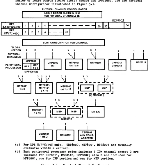
PHYSICAL CHANNELS AND LOGIC BOARDS
In order to determine the quantity of physical channels required, and the number of logic boards (board slots) needed and provided, use the Physical Channel Configurator illustrated in Figure 5-1.
.DPS
8lS2C/62C/70C
·SLOTS NEEDED 3
2
2
3
PHYSICAL CHANNEL CONFIGURATOR
LOGIC BOARD SLOTS IN 10M FOR PHYSICAL CHANNELS (~)
3 4
3 4
SLOT CONSUMPTION PER CHANNEL
3 3 3 3 3 1 1
PHYSICAL CHANNELS
MFP8001
PERIPHERAL URP MTP
PROCESSOR 1x8
URP8000 (8)
,
,
,
MTP8001 (a) 1 x 8
,
~
\
,
URP0600 URPS012 URPS013
MFP8001(a)
MTP0611
1 x 8
3 3 3 3
MTP0611, MTF1151
2 X 16
MSP8000 (8) 1 x 16
3 3 3 3
3 3 3 3
r -
.~
- - -
j,-:" ,
IGGI
L _______
:.l
(8) MSP8002
1
r.
':'..J... - -
j,':'
~
I G 8
1
B
MSP0611 1 x 16
1
I
CSU66011 REQ
L: ______
:J
MSP0612
1
I
CSU~602
I
1
I
CSF6602 AUX CONS.
ADAPTER
(a) For DPS 8/47C/4gC only. URP8000, MTP8001, MFP8001 are mutually exclusive within a cabinet.
(b) Each peripheral processor price includes 1 IOM channel except 2 are included for URP8011, MSP0612, MSP8002j also 2 are included for MFP8001, one for URP portion and one for MTP portion.
Figure 5-1. Physical Channel Configurator
5-3 DP37-02
[image:41.612.60.569.138.704.2]The top portion of the Configurator in Figure 5-1 snows how many slots are provided and can be optionally obtained to hold the logic boards for physical I/O channels in IOM.
o DPS 8/47C/49C IOM provides a fixed complement of 20 slots included in CPS identifier price. No additional slots are available.
o DPS 8/52C/62C/70C IOMs provide a fixed complement of 36 slots included in CPS identifier price. One MXF8005 Channel Expansion option is available for each IOM to provide 18 more board slots. Each additional IOM on DPS 8/52C/62C/70C provides the same base complement of 36 slots in its price and provision for one MXF8005 option in each added IOM.
The lower portion of the Configurator in Figure 5-1 snows the quantity of logic boards (thus board slots) in IOM needed to terminate each I/O cable from a peripheral processor.
o Each solid line from a peripheral processor represents the main channel(s) for the processor. MSP8002, MSP0612 peripheral pro-cessors include two simultaneous main channels in their price. MTP0611 can be configured with a second simultaneous channel. The second MTP0611 simultaneous channel is required if the MTP0611 is to service 9 to 16 tape units in its subsystem.
o The dotted lines from certain peripheral processors imply the optional switched channel feature applied to a main channel. No
switched channel path can have I/O simultaneously with its associ-ated main channel. No dual-channel peripheral processor thus can have more than two data transfers in operation simultaneously, no matter how many switched channel features are used.
NOTE: Each switched channel feature defines a data transfer path and an IOM channel in its price.
o Total the board slots required for each data path termination
If you cannot configure the desired number of peripheral subsystems and their complement of physical channels and switched paths, REGROUP and consider these alternatives:
o In case of a freestanding 10M use the Channel Expansion Option MXF8005.
o Bid a second 10M if the prospect will allow it.
o Use fewer simultaneous channels and/or switched paths.
o Use fewer subsystems of same type.
o Use fewer subsystems.
o Use different mix of sUbsystems.
o Change from DPS 8/41C/49C to DPS 8/52C/62C/10C, if possible.
o If possible, connect UR devices through DN8/C and use no unit record processor.
Determine next the logical channels or data paths which must be
assigned to each physical channel and switched path. and the quantity which may optionally be assigned.
ASSIGNING LOGICAL CHANNELS TO PHYSICAL 10M CHANNELS
Each 10M supports up to 32 logical channels (up to 24 on DPS 8/41C/49C without MXK8001). No options are available. (A logical channel
expansion, providing support for up to a total of 56 logical channels, may be requested via RPQ for DPS 8/52C/62C/10C.)
5-5 DP37-02
See Table 5-1 for a listing of Logical Channel Assignments.
TABLE 5-1. CONFIGURATION FOR LOGICAL CHANNEL ASSIGNMENTS
ADDED PHYSICAL LOGICAL USEFUL PERIPHERAL CHANNELS CHANNELS LOGICAL PROCESSOR REQUIRED (b) REQUIRED (c) CHANNELS (d)
URP (PLUS 1-4/1-B PER
DEVICES) (a) DEVICE
MSP SGL - CHANNEL 1 - 3
MSP DUAL - CHANNEL 2 2 1 - 3 PER
PHY. CH.
(a)
MTP SGL - CHANNEL 1 1 0-1
MTP DUAL - CHANNEL 2 2 0-1 PER PHY. CH.
CSU6601 1 1
DN B/C 1
(a) Including URP and MTP in MFPB001 for DPS B/47C/49C.
(b) Each peripheral processor includes one physical IOM Channel in its price, except URPB011, MSPB002/0612 which includes two.
(c) Don't forget the freestanding MTP, MSP allow for switched path features to be added to each Physical Channel. ~ termination in 10M is a Physical Channel and must be allotted separate logical channels(s), the same quantity for each termination.
The following paragraphs detail the rules for the assignment of IOM logical channels to physical channels.
o Every main and switched physical IOM channel must be assigned one logical channel or data path. URP, MTP, MSP may use more than one logical channel per physical channel, as explained below.
o Assignment is established onsite by Customer Services according to the mix of required and optional logical channels specified by you.
o A table showing the assignment of logical to physical channels and of physical channels to peripherals is given to CP-6 at system startup time. Accordingly, CP-6 always knows what logical channels to use (thus physical channels) to reach a given peripheral
processor, console, or FEP.
In effect CP-6 "sees" the peripherals it wants to reach via the logical channels.
The logical channel concept provides a link to slave program buffer areas - their size and locations. Without such a link, the transfer path to/from memory could not be established.
The following paragraphs explain the reasons for assigning more than one IOM logical channel to a physical cnannel.
1. Use of multiple logical channels per physical channel allows multiple places to which CP-6 can send or can queue I/O commands.
o As long as a logical channel is available, CP-6 can queue in it the next I/O command for a given subsystem, even though the physical channel is busy with data transfers for a prior operation initiated through anut;.her logic"al channel. Otherwise, with a single logical channel, the physical and logical channel would be tied up during the data transfer and interrupt sequence, preventing the overlapped stacking of the next I/O command by CP-6. CP-6 would have to wait for an opportunity to gain access to the single channel.
o The effect here is potentially greater subsystem throughput by using the physical channel more efficiently, stacking commands in front of the subsystem at any time as long as a logical channel is available.
o Looking at it another way, the use of more than one logical channel per physical channel (block multiplexing) allows multiple I/O oper-ations to be in some stage of execution concurrently. There can be as many concurrent stages as logical channels assigned to the sub-system involved. In the URP, e.g., there could be as many as eight card reading/card punching/line printing operations simultaneously, using one physical channel.
5-7 DP37-02
2. Assigning more than one logical channel to a physical channel can help achieve the following advantages:
o Greater subsystem throughput
o Use of fewer physical channels
o Larger number of I/O operations in some stage of execution concurrently
o Better use of physical channels
DEVICES
Figure 5-2 illustrates the concept of multiple logical channels/paths p3r physical channel.
DEVICE PRO· CESSOR
10M
PHYSICAL CHANNEL PIPELINE
LOGICAL CHANNELS
NO.1
-
--NO.2
-
--LOGICAL CHANNELS COMPLETE THE DATA PATHS TO MEMORY
(1
NO .. N)
MEMORY
~ROGRAM A
C
0
<
TOTAL DATA TRANSFER PATH>
~---~--Figure 5-2. Physical Channel and Logical Channel Concepts
5-9 DP37-02
Subsystems Allowing Multiple Logical Channels Per Physical Channel
UNIT RECORD PROCESSOR SUBSYSTEMS
In Unit Record Processor (URP) subsystems there must be one and only one logical channel aSSigned to each unit record device connected to URP. A specific logical channel is assigned to each device.
o URP can handle up to 8 unit record devices (URP0600/8000), or up to
4
unit record devices (URP in MFP8001, URP8011), or up to 2 unit record devices (URP8012/8013).o URP, in combination with its channel and 1 to 8 logical channels in 10M, performs a block (unit record) multiplexing function, allowing up to 8 devices to run simultaneously. URP buffers a full physical record from/for each device and assigns each record to the 10M physical channel as soon as the last record has transferred. Each URP unit record device must be permanently preassigned to a logical channel to be used by CP-6 in issuing commands for it. The logical channel controls the transfer into memory into/from the proper buffer area for the device concerned.
MAGNETIC TAPE PROCESSOR SUBSYSTEMS
In MagnetiC Tape Processor (MTP) subsystems a second (added) logical channel may optionally be aSSigned to each physical channel.
The value of the second logical channel for each physical channel is that it allows CP-6 to send a new command to an open logical channel, even though the physical channel may be transferring data under command of another logical channel aSSigned to the subsystem. As soon as the first operation terminates, a second could be initiated immediately from the command standing by in the second logical channel. CP-6 could then send another command to the first logical channel, which is now open again, etc. If only one logical channel is used, CP-6 cannot have any next command standing by when a command is already in operation.
nISK SUBSYSTEMS
A normal useful maximum of logical channels for each 10M physical channel termination related to a mas~ store subsystem is four.
The number of logical channels assigned for a subsystem shoud not normally exceed the number of spindles in the subsystem. There is no
gain with a greater number of logical channels.
In CP-6, using multiple logical channels gives relatively more
performance improvement than does using multiple physical channels. It is desirable to have as many logical channels as it is expected to have concurrent seeks in progress.
With dual channel MSPs, subsystems commands are more frequently (than with single channel MSPs) serviced almost as soon as they are delivered to the subsystem. As a result, there is relatively less chance to have command queues build up and thus there is less relative effect from multiple logical channels in a dual-channel subsystem than in a single channel subsystem. Dual-channel subsystems will probably give greater throughput in all cases, especially where the subsystem includes more than four or five disk spindles.
Subsystems Allowing Only A Single Logical Channel Per Physical Channel
FEPs
One and only one logical channel must be assigned per IOM-connected (local) FEP. No optional logical channels are permitted.
CONSOLES
One and only one logical channel must be assigned per IOM-connected console. No optional logical cnannels are permitted.
5-11 DP37-02