Performance Analysis of Backoff Exponent Behaviour at
MAC Layer In ZigBee Sensor Networks
Lovish Jaiswal
M-Tech Scholar, S.B.S State Technical Campus Ferozepur, Punjab
Jaswinder Kaur
Assistant Professor, S.B.S State Technical Campus
Ferozepur, Punjab
Gurjeevan Singh
HOD ECE Dep’t, Poly-Wing, S.B.S State Technical Campus
Ferozepur, Punjab
ABSTRACT
Topology is one of the major new paradigms and is the premier research topic in ZigBee based Wireless Sensor Network and has opened up new challenges for researchers throughout the World due to its wide range of applications ranging from medical research to military. IEEE 802.15.4/ZigBee is a worldwide open standard for wireless radio networks which provides network, security, and application support services operating on top of the IEEE 802.15.4 Medium Access Control (MAC) and Physical Layer (PHY) wireless standard and is considered as “technology of choice” due to low-power consumption, cost-effective communication and the reliability they provide.
In this paper, we perform extensive network evaluation by creating nine different scenarios, to observe the effect of backoff exponent parameter at MAC layer with three promising topologies in ZigBee sensor network using the OPNET 14.5 network simulation tool.
General Terms
Topology and Backoff Exponent variation in ZigBee wireless sensor networks.
Keywords
IEEE 802.15.4, ZigBee, WSN, PHY Layer, MAC Layer, OPNET Modeler, Throughput, Load, Delay.
1.
INTRODUCTION
ZigBee defines two layers of the OSI (Open Systems Interconnection) model: the Application Layer (APL) and the Network Layer (NWL), as depicted in Figure 1. Each layer performs a specific set of services for the layer above. The different layers communicate through Service Access Points (SAP’s). These SAPs enclose two types of entities: (1) a data entity (NLDE-SAP) to provide data transmission service and (2) a management entity (NLME-SAP) providing all the management services between layers.
The ZigBee Network Layer (NWK) is responsible for Network management procedures (e.g. nodes joining and leaving the network), security and routing. It also encloses the neighbour tables and the storage of related information. The NWK Layer provides one set of interfaces, the Network Layer Data Entity Service Access Point (NLDE-SAP) used to exchange data with the APS. It was developed by IEEE 802.15.4 Task Group and ZigBee Alliance. ZigBee alliance is responsible for ZigBee standard which uses the transported services of the 802.15.4 network specification just like TCP/IP uses the IEEE 802.11b network specification. The standard was developed to meet the following principal need of low cost, ultra-low power consumption, use of unlicensed radio bands, cheap and easy installation, flexible and extendable
networks. A Wireless Sensor Network can be generally described as a collection of sensor nodes organized into a cooperatively network that can sense and control the environment enabling interaction between persons or embedded computers and the surrounding environment [2]. A Wireless Sensor Network can be generally described as a collection of sensor nodes organized into a cooperatively network that can sense and control the environment enabling interaction between persons or embedded computers and the surrounding environment [2].
Figure 1
usually with a single Omni-directional antenna and a power source like batteries or solar cells. Typical sensors used for such nodes could be temperature, light, pressure, vibration, humidity, sound, radiation, etc. Each of these sensor nodes acquire data, process it and route it to the sink node by multi-hopping. In this paper, we take a closer look at WSN applications. Specifically, we study the effect of topology variation in ZigBee WSNs that assume the presence of one mobile co-ordinator as well as a large number of mobile ZigBee sensors and mobile routers. Moreover, we discuss the challenges as well as potential benefits associated with the deployment of such topologies in ZigBee WSNs in real-world application settings, i.e. application settings that are challenged by physical constraints of real-world environments and employ real-world technology.
2.
IEEE 802.15.4/ZigBee Architecture
802.15.4 is a packet-based radio protocol. It addresses the communication needs of wireless applications that have low data rates and low power consumption requirements. It is the foundation on which ZigBee is built. The following sections will provide a brief overview of each of the four layers, and the ZigBee Device ObjectZigBee is a specification for a suite of high level communication protocols based on an IEEE 802 standard for personal area networks.t
2.1
Physical Layer
The physical layer is provided by the IEEE 802.15.4 standard. The physical layer is ultimately responsible for providing the data transmission service. This layer manages the physical RF transceiver; it performs channel selection as well as energy and signal management routines. As well, this layer exchanges data with the MAC layer above it. The following table shows frequency band, bit rate, chip rate and modulation scheme used in various physical layer standard.
Table 2.1 ZigBee Physical Layer Parameters
PHY Band Freq Data Parameters Parameters Spreading
Bit Rate Symb-ol Rate Modul -ation Rate Chip Rate Modulat-ion 868/915 MHz 868.0-868.6 MHz
20 20 BPSK 0.3 BPSK
MHz-Phy
902.0-928.0 MHz
40 40 BPSK 0.6 BPSK
2.4 GHz Phy
2.4-2.48 GHz
250 62.5 16-ary
Orthog onal
2.0 O-QPSK
2.2
MAC Layer
MAC Layer is responsible for providing reliable communications between a node and its immediate neighbors, helping to avoid collisions and improve efficiency. The MAC Layer is also responsible for assembling and decomposing data packets and frames. The MAC layer defines two types of nodes: Reduced Function Devices (RFDs) and Full Function Devices (FFDs). FFDs are equipped with a full set of MAC layer functions, which enables them to act as a network
coordinator or a network end-device. The MAC layer determines source and destination addressing of frames and is extracted from the IEEE 802.15.4 standard. To provide reliable data transfer, this layer provides multiple access control in the form of Carrier Sense Multiple Access and Collision Avoidance (CSMA/CA).
2.3
Application Layer
The application layer is the highest-level layer defined by the specification, and is the effective interface of the ZigBee system to its end users. It comprises the majority of components added by the ZigBee specification: both ZDO and its management procedures, together with application objects defined by the manufacturer, are considered part of this layer. The application layer is the highest-level layer defined by the ZigBee specification. This layer contains applications running on the ZigBee network and thus provides the effective interface to the user [5][7][12]. A ZigBee application consists of a set of Application Objects (APOs) spread over several nodes in the network..An APO is a piece of software (from an application developer) that controls a hardware unit (transducer, switch, and lamp) existing on the device. Each APO is assigned a locally unique endpoint number that further APOs can utilize as an extension to the network device address to act together with it. The ZigBee Device Object (ZDO) is a special object which offers services to the APOs as it allows them to discover devices within the network and the service they implement. It also provides communication, network and security management services. The Application Sub layer (APS) provides data transfer services for the APOs and the ZDO A single node can support 240 applications, where application number 0 is reserved for the ZigBee Device Object. Applications on this layer can provide services such as building automation, temperature control, industrial control and wireless sensor monitoring
2.4
ZigBee Device Object
It defines the role of a device within the network (coordinator, router or end device), initiates and/or responds to binding and discovery requests, and establishes a secure relationship between network devices. It also provides a rich set of management commands defined in the ZigBee Device Profile ZigBee defines three types of devices, i.e. ZigBee Coordinator (ZC), ZigBee Router (ZR), and ZigBee End Devices (ZED)
Figure 2 ZigBee Device Object
ZigBee Router (ZR): These devices extend network area coverage, dynamically route around obstacles, and provide backup routes in case of network congestion or device failure. They can connect to the coordinator and other routers, and also support child devices. It participates in multi-hop routing of messages in mesh and Cluster-Tree networks; Associates with ZC or with previously associated ZR in Cluster-Tree topologies; Acts as an IEEE 802.15.4 PAN Coordinator; Is a Full Functional Device (FFD) – implements the full protocol stack.
ZigBee End Device (ZED): These devices can transmit or receive a message, but cannot perform any routing operations. They must be connected to either the coordinator or a router, and do not support child devices. They also do not allow other devices to associate with it, does not participate in routing and act as a sensor/actuator node. ZED’s also known as Reduced Function Device (RFD) – implementing a reduced subset of the protocol stack.
3.
Related work
Several papers have addressed the issue of performance analysis in IEEE 802.15.4. These papers mainly focus on the slotted version of IEEE 802.15.4 in a multihop environment or with multiple senders and receivers. The performance evaluation of [7] studies the throughput-energy-delay tradeoffs based on NS-2 simulations. It was found that in low duty networks a significant energy saving can be achieved by using the super frame structure, but these savings come at the cost of significantly higher latency and lower bandwidth. A more complete simulation based performance study was done in [8]. An interesting result is that in a no beaconed mode and for low rate applications the packet delivery ratio of IEEE 802.15.4 is similar to IEEE 802.11. In [9] it was shown that the optimal network performance for slotted CSMA/CA is reached with an offered load in the range of 35% to 60%
A more theoretical approach was used in [10] where the network is modelled using discrete Markov chains. The throughput and energy consumption were analyzed in saturation conditions for a varying number of nodes in a star topology. In [11] a similar model is defined that considers more parameters. The results show that the average access delays may be quite high if the throughput exceeds 50%. This paper will focus on the un-slotted version of 802.15.4. The approach is similar as the one used in [12] and [13] for IEEE 802.11. A general formula is drawn up and analyzed. The frequency band with the most number of channels and highest data rates in IEEE 802.15.4 is the 2.4 GHz band. This is the same band used by IEEE 802.11 (Wi-Fi) [14] and IEEE
802.15.1 (Bluetooth) [15]. These technologies will cause interference when used simultaneously. The interference between Wi-Fi and 802.15.4 was investigated in [16] and [17]. It was concluded that Wi-Fi interference is detrimental to a WPAN using 802.15.4. However, if the distance between the IEEE 802.15.4 and IEEE 802.11b radio exceeds 8 meter, the interference of IEEE 802.11b is almost negligible.
4.
Simulation Model and Scenarios
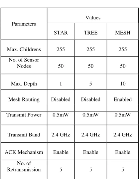
In order to accomplish this evaluation, an OPNET simulation model for the IEEE 802.15.4 supporting the slotted CSMA/CA mechanism was used as a means to compare experimental and simulation results, for the same scenarios. The simulation shows the expected behaviour of the system based on its simulation model under different conditions. Hence, the purpose of this simulation model is to determine the exact model and predict the behaviour of the real system. For the purpose of simulation, we will use OPNET Modeler 14.5, which provides a leading environment for modelling and simulations. This simulation tool provides a comprehensive development environment to support modelling of communication networks and distributed systems. This version of simulation supports three types of topologies: star, mesh and cluster-tree topology, where communication takes place between a central controller – PAN coordinator, routers and devices. We are using only one ZigBee Coordinator (ZC) in each topology, seven ZigBee routers (ZR) and fifty ZigBee End devices (ZED). All ZR’s and ZED’s are mobile. The comparison includes the following statistics: end-to-end delay, number of hops and global throughput.
Table 4.1
Parameters
Values
STAR TREE MESH
Max. Childrens 255 255 255
No. of Sensor
Nodes 50 50 50
Max. Depth 1 5 10
Mesh Routing Disabled Disabled Enabled
Transmit Power 0.5mW 0.5mW 0.5mW
Transmit Band 2.4 GHz 2.4 GHz 2.4 GHz
ACK Mechanism Enable Enable Enable
No. of
Packet Size (1024) (1024) (1024)
Packet Threshold -95 -95 -95
Max. No of Back offs
5 5 5
Beacon Order 6 6 6
Max. Router 10 10 10
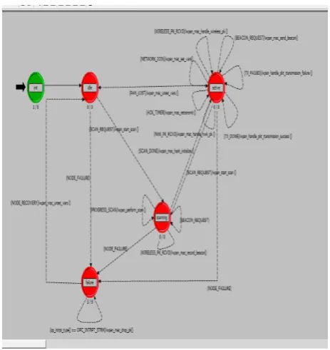
[image:4.595.49.276.70.212.2]The node model and process model of ZigBee Sensor network architecture are also shown in figure 2 and figure 3 respectively. Process models are used to specify the behavior of processor and queue modules which exist in the Node Domain. Process models are used to implement a wide variety of hardware and software subsystems, including communication protocols, algorithms, shared resources such as disks or memory, operating systems, queuing disciplines, specialized traffic generators, custom statistic collectors, and so on where as node models are defined as a collection of modules representing distinct functional areas of the node. Certain modules are limited in the types of behavior they can represent; for example, the various transmitters and receivers represent interfaces to links defined in the network domain.
Figure 3 Process Model of ZigBee Co-ordinator.
Figure 4 Node Model of ZigBee Device Object.
In the Star topology, ZC allows up to 255 child nodes to be connected, and the maximum depth is set to one. We set the Acknowledgment mechanism to “Enable” for every ZED, so every ZED can send an acknowledgment to its parent in order to confirm that it receives the packets
5.
Simulation Results
After setting all these parameters, ZigBee network model is ready for the simulation. The simulation results concerning the Throughput, End to End Delay, No. of Hops, Load per PAN, across the full ZigBee stack, under different topology-deployment strategies with variable Backoff Exponents, are analysed.
5.1
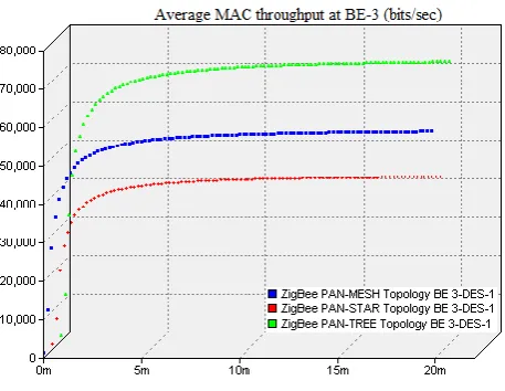
Throughput
[image:4.595.54.286.406.652.2]Figure 5 Throughput at Backoff Exponent-1
Figure 6 Throughput at Backoff Exponent-2
Figuure 7 Throughput at Backoff Exponent-3
The above figures shows that throughput is maximum in tree topology but when Backoff exponent comes into play it affects the throughput significantly i.e. at BE-2 mesh topology give better throughput as compare to BE-1 and BE-3, whereas at BE1 and BE-3 tree and star topology has better throughput as compare to BE-2.
5.2
End to End Delay
End-to-end delay refers to the time taken for a packet to be transmitted across a network from source to destination.
[image:5.595.326.554.299.435.2]Figure 8 End to End Delay at Backoff Exponent-1
Figure 9 End to End Delay at Backoff Exponent-2
Figure 10 End to End Delay at Backoff Exponent-3
After analyzing these results we observe that in tree topology end to end delay is minimum at BE-1, whereas end to end delay is minimum at BE-2 and BE-1 for mesh and star topology respectively.
5.2.1
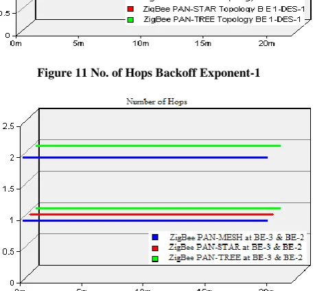
Number of Hops
[image:5.595.63.292.464.641.2] [image:5.595.326.555.466.616.2]intermediate devices (like routers) through which data must pass between source and destination.
[image:6.595.58.287.113.298.2]Figure 11 No. of Hops Backoff Exponent-1
Figure 12 No. of Hops at Backoff Exponent-2 & 3
Hop counts are often useful to find faults in a network, or to discover if routing is indeed correct. In our case the number of hop count is maximum in tree topology at BE-1 while at BE-2 & BE-3 tree has lesser number of hop. Effect of backoff exponent towards mesh and star toplogy is insignificant.
5.2.2
Network Load
Network load represents the total load (in bits/sec) submitted to 802.15.4 MAC by all higher layers in all WPAN nodes of
[image:6.595.58.288.214.426.2]Figure 13 Netwrork load at Backoff Exponent-1
Figure 14 Network load at Backoff Exponent-2
Figure 15 Network load at Backoff Exponent-3
the network. Network load also refers to the amount of data (traffic) being carried by the whole network. Study shows that tree and mesh topology handles minimum traffic loads at Backoff Exponent-3 whereas star topology is unaltered towards the variation of backoff exponent value in the network.
6.
Conclusion
In this paper we evaluate the ZigBee/IEEE 802.15.4 standard using three possible topologies and the effect of variation of Backoff exponent variable at MAC layer in ZigBee-WSN based Networks. However, a detailed analysis of ZigBee WSN Network by means of different parameters like throughput, end to end delay, number of hops, network load are affected significantly with the variation of backoff exponent at MAC layer in 802.15.4 standard and this reveals the characteristics of the IEEE 802.15.4 topology formation process and the relevant impact on the overall network performance. The results show that tree topology outperforms among all other topologies but. Overall, the performance evaluations show that the ZigBee Network performance related to formation and re-configuration are greatly affected by this parameter.
7.
REFERENCES
[image:6.595.321.559.262.409.2] [image:6.595.59.280.580.749.2][2] Francesca Cuomo et al. “Performance analysis of IEEE 802.15.4 wireless sensor networks: An insight into the topology formation process”, Computer Networks 53 (2009) 3057–3075.
[3] Yu-Kai Huang et al., “A Comprehensive Analysis of Low-Power Operation for Beacon-Enabled IEEE 802.15.4 Wireless Networks” IEEE Transaction on
Wireless Communications, VOL. 8, NO. 11, Nov 2009 [4] Chiara Buratti et al. “Performance Analysis of IEEE
802.15.4 Beacon-Enabled Mode” IEEE Transaction On Vehicular Technology, VOL. 59, NO. 4, MAY 2010. [5] Azadeh Faridi et al. “Comprehensive Evaluation of the
IEEE 802.15.4 MAC Layer Performance With Retransmissions” IEEE Transaction On Vehicular Technology, VOL. 59, NO. 8, OCTOBER 2010
[6] Zdenˇek Hanzálek, et al. “Energy Efficient Scheduling for Cluster-TreeWireless Sensor Networks With Time-Bounded Data Flows: Application to IEEE 802.15.4/ZigBee” IEEE Transaction On Industrial Informatics, Vol. 6, NO. 3, August 2010.
[7] Yu-Kai Huang et al. “Distributed Throughput Optimization for ZigBee Cluster-Tree Network” IEEE Transaction On Parallel and Distributed Systems, VOL. 23, NO. 3, March 2012
[8] Chong, C. and Kumar, P. “Sensor s Networks: Evolution, Opportunities, and Challenges”, Proceedings of the IEEE, vol.91, No.8, August 2003.
[9] B.E. Bilgin, V.C. Gungor “Performance evaluations of ZigBee in different smart grid environments”, Computer Networks 56 (2012) 2196–2205.
[10]Kumar, H., Sarma, D., Kar, A. and Mall, R. “Energy Efficient Communication Protocol for a Mobile Wireless Sensor Network System” in International Journal of Computer Science and Network Security, Vol.9, No.2, February 2009.
[11]Shi Longlong, et al., “The Research and Simulation of CSMA/CA Mechanism of ZigBee Protocol”, 2012 International Workshop on Information and Electronics Engineering (IWIEE), Procedia Engineering 29 (2012) 3466 – 3471
[12]Mahlknecht, S. “WSSN (Wireless Self-sustaining Sensor Network) Project,” 2005,
[13] Mahlknecht, S. and Bock, M. “CSMA-MPS: a minimum preamble sampling MAC protocol for low power wireless sensor networks,” in Proceedings of the IEEE International Workshop on Factory Communication Systems (IWFC), 22-24 Sept. 2004, Vienna, Austria, 2004, pp. 73–80 .
[14]Akyildiz, I. F., Su, Sankarasubramaniam, W. Y. and Cayirci, E. “Wireless sensor networks: A survey,” Computer Networks (Elsevier), vol. 38, pp. 393-422, 2002.
[15]Pottie, G. J. and Kaiser, W. J. “Wireless Integrated Network Sensors,” Communications of the ACM, vol. 43, no. 5, pp. 551–558, May 2000.
[16]Al-Karaki, J. N. and Kamal, A. E. “Routing techniques in Wireless Sensor Networks: A survey”, Department of Electrical and Computer Engineering Iowa State University, Ames, Iowa 50011
[17]Bluetooth SIG, “Bluetooth Specification v1.1,” 2001, http://www.bluetooth.org/spec/, Last accessed on 15 July 2011.
[18]Sangheetaa Sukumran et al., Reputation based Dynamic Source Routing Protocol for MANET International Journal of Computer Applications (0975 – 888) Volume 47–No.4,June2012.
[19]A. Cunha, M. Alves, and A. Koubaa. (2010) Implementation of the ZigBee Network Layer with Cluster-tree Support [Online]. Available:
http://www.openzb. net/research.php, 2010.
[20]P. Jurcik, A. Koubaa, M. Alves, E. Tovar and Z. Hanzalek, “A Simulation Model for the IEEE 802.15.4 protocol: Delay/Throughput Evaluation of GTS Mechanism,” in 15th Annual Meeting of the IEEE
International Symposium on Modeling, Analysis and Simulation of Computer and Telecommunication Systems (MASCOTS ‘07), Istanbul, Turkey, 2007, pp. 24-26. [21]Paolo Baronti et al. “Wireless sensor networks: A survey
on the state of the art and the 802.15.4 and ZigBee standards”, Computer Communications 30 (2007) 1655– 1695.