N A N O E X P R E S S
Open Access
Electroless etching of Si with IO
3
–
and related
species
Kurt W Kolasinski
1*and Jacob W Gogola
2Abstract
We have previously derived seven requirements for the formulation of effective stain etchants and have demonstrated that Fe3+, Ce4+, and VO2++ HF solutions are highly effective at producing nanocrystalline porous silicon. Here, we show that Cl2, Br2, I2, ClO3–, BrO3–, IO3–, I–, and I3–induce etching of silicon when added to HF. However, using the strict definition that a pore is deeper than it is wide, we observe little evidence for porous layers of significant thickness but facile formation of pits. Iodate solutions are extremely reactive, and by the combined effects of IO3–, I3–, I2, and I–, these etchants roughen and restructure the substrate to form a variety of structures including (circular, rectangular, or triangular) pits, pyramids, or combinations of pits and pyramids without leaving a porous silicon layer of significant thickness.
Keywords:Porous silicon, Etching, Nanostructures, Thin films, Hydrofluoric acid, Iodate, Iodine, Iodide, Triiodide PACS:81.07.-b, 81.65.C, 68.55.ag
Background
Stain etching is potentially a fast, easy, and inexpensive method of producing porous silicon (por-Si) on arbitrar-ily shaped surfaces. When mixed with HF(aq), Fe3+, Ce4+, and VO2+have all previously been shown [1-5] to be
cap-able of producing uniform layers of por-Si with thick-nesses up to 20 μm. Perhaps more importantly for applications, the ability to etch arbitrarily shaped sub-strates means that stain etchants can also efficiently etch powdered silicon. Loni et al. [6] have demonstrated that inexpensive metallurgical-grade silicon powder can be converted to high-surface-area por-Si powder. Porous silicon powder may find applications as a high-energy material [7], in drug delivery [8], biosensing [9], and as an anode material in lithium-ion batteries [10].
When silicon is exposed to an aqueous fluoride solu-tion, the morphology of the etched surface depends sen-sitively on the balance of the surface reactions that occur. Oxidation by water dissociation or step flow etch-ing initiated by OH– both favor the formation of uni-form surfaces, whereas direct Si atom dissolution via the
Gerischer mechanism [11,12] favors por-Si formation. Surface chemistry alone does not lead to por-Si forma-tion. The chemistry must be coupled to charge carrier dynamics to form a porous film. In electroless etching to form por-Si (stain etching), the quantum confinement-related shift of the Si valence band causes fluoride etch-ing of Si to be self-limitetch-ing, which is responsible for nanostructure formation [13].
We have undertaken a series of experiments to de-velop new stain etchants and better understand the dy-namics of etching [1-5]. The seven requirements for the formulation of an effective stain etchant are [13,14] (1) an acidic fluoride solution, (2) sufficiently high fluoride concentration compared to the oxidant concentration, (3) the oxidant must be able to inject holes into the Si valence band at an appreciable rate; thus, its electrode potential should be more positive than approximately +0.7 V, (4) oxide formation needs to be slow or nonexis-tent, (5) the oxidant and all products are soluble, (6) film homogeneity is enhanced if the oxidant's half-reaction does not evolve gas, and finally, (7) the net etching reac-tion from hole injecreac-tion to Si atom removal (including the reactions of any by-products) has to be sufficiently anisotropic (attacking all kinds of sites but only at the bottom of the pore) to support pore nucleation and propagation.
* Correspondence:[email protected]
1
Department of Chemistry, West Chester University, West Chester, PA 19383, USA
Full list of author information is available at the end of the article
Previous work has shown that etching of silicon is affected by the addition of halogens and halogenates to fluoride solutions. Salem et al. [15] were able to increase the rate of anodic groove formation caused by etching at the contact of a Pt wire with a Si substrate by adding 1 mM I2to the etchant. Seo and co-workers investigated
etching induced by KIO3and KBrO3[16-18]. However,
alkali metals precipitate readily with the etch product SiF62–[19]. Precipitation hinders the reproducible
forma-tion of uniform layers, and no significant por-Si layers were observed in these studies.
Adachi and co-workers have performed a number of studies with iodates and other oxidants. Xu and Adachi [20] investigated etching KIO3+ HF solutions with and
without illumination at ≥600 nm from a Xe lamp. They found no formation of por-Si in the absence of illumin-ation. When illuminated, they attributed observed photoluminescence (PL) to microporous layers with a thickness of ≤80 nm. However, it should be noted that PL has previously been observed from the interface of hexafluorosilicates with silicon [19] and that the lateral size (20 to 100 nm) of features they observed by atomic force microscopy was often larger than the reported film thickness. They also report that por-Si emitting stable red PL can be formed anodically in the presence of the very low concentrations of I2provided by a saturated I2/
50% HF solution [21]. During anodic etching of n-type wafers [22], the addition of KIO3increased the observed
pore size. Their report that 10–4 M KIO3 solutions do
not react with Si surfaces runs counter to the high re-activity reported here for HIO3solutions.
Halogenate + HF solutions can be made that meet all of the criteria for stain etchants except the last. Therefore, these species are not suitable for por-Si formation even though they very effectively induce etching and restructur-ing of the surface. On the other hand, we demonstrate that HIO3+ HF is quite capable of restructuring the
sur-face to produce other sorts of nano- and micro-structures.
Methods
Diffuse reflectance infrared spectroscopy, cross-sectional scanning electron microscopy, photoluminescence, and white light reflectometry have been used to measure the thickness, surface area, and porosity of por-Si thin films and restructured Si substrates made by oxidant + HF etching in various solutions as a function of solution composition and etch time. Scanning electron micros-copy (SEM) was performed with an FEI Quanta 400 ESEM (Hillsboro, OR, USA). The SEM operates with integrated Oxford INCA energy-dispersive X-ray spec-troscopy (Abingdon, UK). Fourier transform infrared spectroscopy was performed as described previously [2] with a Nicolet Protégé 460 (Madison, WI, USA). Reflect-ometry was performed on an Ocean Optics USB2000
spectrometer with a DH-2000 deuterium tungsten halo-gen lamp from 360 to 1,100 nm (Dunedin, FL, USA). Photoluminescence measurements were made on a Cary Eclipse fluorescence spectrophotometer with excitation at 350 nm (Agilent Technologies, Inc., Santa Clara, CA, USA).
All etching was performed on either 0- to 100-Ω cm or 14- to 20-Ω cm p-type test-grade Si(100) wafers, or mechanical-grade n-type Si(111) wafers (University Wafer, Boston, MA, USA). The wafers are cleaned by ultrasonication in acetone then ethanol followed by rins-ing in water prior to etchrins-ing. Exposure of the samples to air after cleaning is minimized. After etching, samples are rinsed in water and ethanol, and then dried in a stream of Ar gas.
Table 1 lists the standard electrochemical potentials of a number of oxidants of interest. We have shown previ-ously [1-5] that Fe3+, Ce4+, and VO2+ are quite capable
for facile production por-Si but HCrO4– and MnO4– are
less reliable for por-Si formation. Both are capable of in-ducing etching. Chromate is particularly effective at etching defects in silicon [23]. Thus, its solutions may exhibit too much anisotropy for uniform por-Si forma-tion. Permanganate is usually supplied from a Na or K salt, and as mentioned above [19], alkali metals precipi-tate readily with the etch product SiF62–, which can lead
to interferences and inhomogeneities.
Two other oxidants that appear in Table 1 are IrCl26 and S2O28. We have found that IrCl
2
[image:2.595.304.539.486.723.2]6 is capable of
Table 1 StandardE°of oxidants of interest and approximate positions of VBM at the silicon surface
Species E°/V Half-reaction
I2 0.5355 I2þ2e!2I
VBM (n, surface) 0.67
Fe3þ 0.771 Fe3þþe!Fe2
IrC12
6 0.8665 IrC126þe!IrC136
VBM (p, surface) 0.9
NO3 0.957 NO3 þ4Hþ þ 3e!NOðgÞ þ H2O
VOþ2 0.991 VOþ2 þ2Hþþe!VO2þþH 2O
Br2 1.0873 Br2þ2e!2Br
IO3 1.195 IO3 þ6Hþþ5e!1
2 I2þ3H2O HCrO4 1.350 HCrO4 þ7Hþþ3e!Cr3þþ4H
2O
Cl2 1.35827 C12 þ2e!2C1
ClO3 1.47 ClO3þ6Hþþ5e!1
2 C12þ3H2O BrO3 1.482 BrO3 þ6Hþþ5e!1
2Br2þ3H2O MnO4 1.507 MnO4 þ8Hþþ5e!Mn2þþ4H 2O
Ce4þ 1.72 Ce4þþe!Ce3þ
forming por-Si films and will report on this in detail else-where. We have attempted a few cursory etching experi-ments with K2S2O8or (NH4)2S2O8in 48 wt.% HF. There
are signs of reaction, such as bubbling and waviness on the surface during etching, but we have not observed por-Si film formation. Grains of the solid dropped into HF induced vigorous bubbling, which slows markedly once they have dissolved. We are in the process of trying to synthesize H2S2O8. This is a better candidate, as it will
not suffer from precipitation interferences.
Here, we concentrate on solutions made up from NaI (Fisher certified; Pittsburgh, PA, USA), NaIO3 (Fischer
certified), HIO3 (Sigma-Aldrich ACS reagent, >99.5%;
St. Louis, MO, USA), I2 (Fisher USP resublimed), HI
(Sigma-Aldrich, 57 wt.% in water, unstabilized), NaBrO3
(Fisher certified), Br2, HBr, NaClO3 (Fisher certified),
Cl2, and HCl. These are added to 48 wt.% HF (Acros
Organics ACS reagent, Fair Lawn, NJ, USA).
Results and discussion
The iodate ion IO3–very effectively injects charge into Si
through the five-electron process described in Table 1. The induced etching is highly exothermic and rapid. HIO3
concentrations in the range of 5 × 10⁻⁴to 1 × 10⁻²M have all been found to produce rapid etching.
Etching in fluoride solutions leads to the formation of the hexafluorosilicate ion SiF62– and H2 bubbles by the
reaction scheme [1]
SiþOxþ!SiþþOx Siþþ3HF!HSiF3þ2Hþþe
HSiF3þ3HF!H2SiF6þH2
SiðsÞ þOxþþ6HF!H2SiF6þOxþ2HþþH2ð Þ þg e
Hþþe!1 2H2ð Þg
: 8 > > > > > < > > > > > : ð1Þ
For brevity, (aq) is dropped. Thus, as mentioned above, salts containing Na or K should be avoided as a source of IO3– to avoid precipitation. Using NaIO3, we
could easily induce precipitation of Na2SiF6 with
suffi-ciently extensive etching. Alkali metal hexafluorosilicates are white powders.
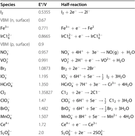
Observing the etching of Si in HIO3+ HF, one sees
bubble formation on the crystal accompanied by the for-mation of a rough-looking surface and dark particulates. Rinsing the crystal in ethanol releases the particulates and causes the solution to take on the typical red color-ation of a tincture of iodine. Clearly, I2is being formed
during etching. Figure 1 displays a typical SEM micro-graph of a Si substrate etched in an aqueous solution of HIO3/HF. The surface is rough and pitted with no
indi-cation of the formation of a nanoporous layer.
The precipitation of I2can be avoided by the addition
of ethanol to the etchant. Ethanol addition significantly
reduced the etch rate of most stain etchants [2]; how-ever, that was not a problem for the highly reactive iod-ate system. Bubble formation and roughening were again observed. In this case, the etchant gradually turned red, reached a maximum intensity, and then became clear. At this point, the bubbling also ceased. I2was being
pro-duced by the reduction of IO3–; however, it was also
being consumed by a secondary reaction. The dissol-ution and etch rates can be enhanced by performing the etching with simultaneous ultrasonic agitation.
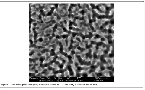
As shown in Figure 2, significant surface restructuring is possible with HIO3+ ethanol + HF etching. The surfaces
are extremely rough and have a gray to black appearance. The lack of visible photoluminescence and the absence of a significant Si-H peak in the infrared absorption spectrum indicate the absence of a nanoporous layer. The surface features are largely uncontrollable. The same sam-ple can exhibit regions covered with pyramids, as shown in Figure 2a when the substrate is (100) oriented. These pyramids have smooth faces, but in between, there is sig-nificant roughness and a sigsig-nificant number of circular pits 45 to 110 nm in diameter. Other regions will exhibit rectangular features as shown in Figure 2b. As the micro-graph in panel (d) shows, these roughly 150-nm features are pits rather than pores. If the substrate orientation is switched to (111), triangular rather than rectangular pits are found. This is to be expected for anisotropic etching with etch rates that are dependent on surface orientation as found in the alkaline etching of Si [24]. Other regions exhibit corral-like structures (on both (111) and (100) orientations) with nested pits within pits and significant roughness, as shown in panel (c). Regions such as those shown in panels (b) and (c) or the between-pyramid regions might be labeled por-Si; however, because they do not exhibit a depth significantly longer than their width, large surface area (i.e., the lack of significant Si-H IR ab-sorption), nor photoluminescence, we refrain from desig-nating them as por-Si.
We believe that IO3–-induced etching is capable of
pro-ducing nanoporous silicon. This generates a great deal of surface area, which enhances the reactivity of the Si sub-strate toward other species. This facilitates such major re-structuring of the surface because the chemistry of iodine-containing species in solution is extremely com-plex, and it is impossible to separate IO3–-induced
chemis-try from that induced by I–, I2, and I3–. As we will show
below, all of these species are capable of etching Si. The first two lead to smooth isotropic etching, and the last leads to anisotropic etching. The combination and bal-ance of these chemistries with IO3–-induced etching leads
to the great variety of surface features observed.
There are two possible production paths for I2. The
first is the reduction of IO3–listed in Table 1. The second
IO3 þ5Iþ6Hþ!3I2þ3H2O E
¼0:6595 V; ð2Þ
which occurs spontaneously when IO3–and I–are mixed.
A relatively small amount of I2can be lost to adsorption
on the surface [25]. Two possible sinks for I2, apart from
simple precipitation of I2(s), are a thermally initiated
etch reaction involving I2 as well as a fluoride species
(because I2 in solution by itself does not etch silicon in
solution at room temperature, see below),
SiþxI2þyHF!H2SiFyI2xþ1
2ðy2ÞH2ð Þg ; ð3Þ
(with x= 1 or 2 and y= 4 or 2) and the reaction with iodide to form triiodide,
I2þI!I3: ð4Þ
The stoichiometry of reaction (3) is notional. By a thermal reaction, we intend to imply that it is initiated by the chemical reaction of I2dissociative adsorption on
the surface of silicon as opposed to a hole injection step. Subsequent steps involve some unidentified combination of fluoride species. Because the first step does not in-volve hole injection, this reaction would not be con-strained by quantum confinement effects to be self-limiting [13] and would, therefore, be capable of destroy-ing por-Si. It should be noted that all silicon tetrahalides are unstable in water and subject to reactions of the type
SiX4þ2HF!H2SiX4F2: ð5Þ
Iodide production can occur from the reduction of I2
listed in Table 1 (though the rate of this should be low based on theE°value), the reduction of triiodide,
I3 þ2e!3I E¼0:536 V; ð6Þ
or an alternative iodate reduction reaction,
IO3 þ6Hþþ6e!Iþ3H2O E
¼1:085 V: ð7Þ
The chemical reactions of Cl2, Br2, and I2, when
exposed as gases to Si surfaces, are known to preferen-tially attack step sites [26]. In semiconductor processing, this reaction is carried out at high temperatures; none-theless, an analogous reaction in solutions would be expected to destroy por-Si. The high surface area and defect-laden surfaces of por-Si would be much more sus-ceptible to such reactions in comparison to a polished silicon surface. Therefore, it is not surprising that the production of halogens in solution should lead to the destruction of por-Si. That Br2destroys por-Si was
previ-ously reported by Kelly and co-workers [27].
Now, we turn to the etch chemistry of I–, I2, and I3–
with polished Si and por-Si surfaces. To do so, we made up a series of solutions from HI, I2, HI + I2, or NaI + I2.
[image:4.595.60.541.85.385.2]These were dissolved either in water or in water/ethanol
solutions and exposed to mirror finish Si(100) and Si(111) surfaces. The Si surfaces were hydrogen terminated as their oxide layers were stripped by etching first in HF. Al-ternatively, a layer of por-Si was produced with either a FeCl36H2O + HF or a V2O5+ HF solution. The layer
exhibited a uniform blue or green color indicative of a homogeneous por-Si film. Immediately after being made and rinsed, these layers were exposed to this set of solu-tions. No etching of either the polished Si surfaces or the
por-Si films was noted. Iodide, iodine, and triiodine solu-tions do not react with either flat, defect-free surfaces or the high-surface-area, defect-laden surfaces of por-Si when HF is not also added to the solution. This result is consistent with the work of Haber et al. [25] who showed that I2/methanol solutions can lead to the formation of
Si-I and Si-OCH3bonds; however, they gave no indication
[image:5.595.54.541.90.573.2]for an increase in surface area or other signs of etching. That iodide-containing but HF-free solutions can affect
Figure 2SEM micrographs of Si(100) wafers etched in 0.07 M HIO3in 3:5 ethanol/HF solutions.(a) Etch time = 300 s, 45° perspective. (b)
the surface of silicon or por-Si but do not etch the surface is also consistent with other reports of solar cell charac-teristics and flatband potentials [28,29] or photolumines-cence properties [30] that shift upon exposure to iodide-or triiodide-containing solutions.
We investigated the etch behavior of solutions con-taining I–, I2, and I3–to which HF has also been added.
Neither HI + HF nor I2+ HF solutions exhibit
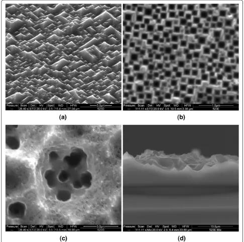
appre-ciable reactivity with polished Si surfaces. We note no bubbling on the faces of the crystals, and the surfaces re-tain their mirror finishes after rinsing. Occasionally, a few small bubbles may appear after many minutes on scratches or the edges of the crystals. This indicates that there is some reactivity with defects but very low reactiv-ity with well-ordered terraces. An I3–-containing solution
can roughen a polished Si surface. This is a slow process requiring about half an hour or more. As shown in Fig-ure 3, this etch process also exhibits a degree of crystal-lographic anisotropy. We exposed a p-type Si(100) crystal to, for example, a 0.005 M I2+ 0.04 M NaI in 3:1
ethanol/HF solution or an 0.004 M in I2, 0.02 M in NaI
in 25% HF. Most of the etch pits are circular. However, as shown in Figure 3, some of the pits gradually convert to inverted pyramids, often with approximately 100-nm circular pits at their apex. The pyramids are 750 nm to 2μm on a side. There is no evidence of nanoporous sili-con on such samples. No bubbles formed during etch-ing. This may be related to the slow etch rate.
Now, we address the etch chemistry of por-Si films with solutions containing I–, I2, and I3–to which HF has
also been added. HI + HF, I2+ HF + ethanol, and HI + I2+
HF solutions all remove por-Si layers accompanied by the formation of bubbles. The rate at which the por-Si is destroyed is dependent on the concentration of the iod-ine species. Interestingly, when I– and I2destroy por-Si,
they leave behind a nearly mirror-like Si substrate. These two species, therefore, facilitate step flow etching in HF solutions. This is consistent with their lack of reactivity with the terraces of polished surfaces. I3–-containing
solutions, on the other hand, remove por-Si to reveal a rough and pitted surface much like the one shown in Figure 3. Again, this is consistent with the more aggres-sive and anisotropic nature of I3–-induced etching. All
three of these species destroy nanoscale Si structures; therefore, the initiation step and etch rate of each reac-tion must not be constrained by quantum confinement.
These results are general for the other halogens and halogenates. A 0.04-M Br2+ HF solution led to etching
of flat Si surfaces, which remained flat after etching. If the solution was exposed to a por-Si layer, the por-Si was removed. As mentioned above, this is consistent with the work of Bressers et al. [27]. A solution of 0.07 M NaBrO3+ HF also etched Si. By the solution
color change observed, it was clear that the reaction of BrO3–generated Br2in solution. As expected, the etching
[image:6.595.58.541.447.714.2]of a polished Si surface led to a flat surface after etching.
Similarly, a 0.2-M KClO3+ HF solution led to the
etch-ing of polished silicon, which resulted in the formation of Cl2in solution and a flat final surface. Neither one of
these oxidants etched Si with the same degree of anisot-ropy as observed with iodate. This may be due to the more reactive nature of Br2 and Cl2 as compared to I2
and the lack of a species analogous to I3–.
Conclusions
Etching of silicon in iodate solutions is extremely com-plex and difficult to control. Surface structures including pits (circular, triangular, or rectangular), pyramids (erect or inverted), roughness, and pits within pits or pits be-tween pyramids have been obtained. This complexity is engendered by a competition of several isotropic and an-isotropic chemical and electrochemical reactions of IO3–,
I3–, I2, and I–. Whereas I2and I–much prefer to attack
de-fect and step sites leading to flat surfaces, I3–is able to
at-tack terrace sites and exhibits a degree of crystallographic anisotropy as evidenced by the production of crystallo-graphically defined features. We believe that the ex-tremely high etch rates induced in IO3– solutions are
caused by IO3–being able to increase the surface area and
defect density of the Si substrate through the formation of porous silicon. Whereas a substantial porous layer might be formed in a non-recirculating flow through etch system, porous Si is subsequently destroyed by the actions of I3–, I2, and I–as these reaction by-products build up in
the etchant. Bromate and chlorate etching are not as complex. However, these only lead to flat surfaces at least in part due to the higher reactivity of Br2and Cl2in
solu-tion, both of which lead to step flow etching.
Competing interests
The authors declare that they have no competing interests.
Authors’contributions
Both authors designed, analyzed, and performed the experiments. KWK was primarily responsible for the writing of this report. Both authors read and approved the final manuscript.
Acknowledgements
This work is supported by Vesta Sciences, West Chester University, Pennsylvania State System of Higher Education, Center for Microanalysis and Imaging, Research and Training (CMIRT) at WCU and the expert technical assistance of Frederick Monson. Caroline Schauer is most gratefully thanked for making available a thin film reflectometry system.
Author details
1Department of Chemistry, West Chester University, West Chester, PA 19383, USA.2Present address: Chemistry Department, Exelon Corporation, Plant Services Building, 1848 Lay Road, Delta, PA 17314, USA.
Received: 19 May 2012 Accepted: 9 June 2012 Published: 20 June 2012
References
1. Kolasinski KW, Yadlovskiy J:Stain etching of silicon with V2O5.Phys Status
Solidi C2011,8:1749–1753.
2. Kolasinski KW, Hartline JD, Kelly BT, Yadlovskiy J:Dynamics of porous silicon formation by etching in HF + V2O5solutions.Mol Phys2010,
108:1033–1043.
3. Dudley ME, Kolasinski KW:Stain etching with Fe(III), V(V) and Ce(IV) to form microporous silicon.Electrochem Solid State Lett2009,12:D22–D26. 4. Dudley ME, Kolasinski KW:Structure and photoluminescence studies of porous silicon formed in ferric ion containing stain etchants.Phys Status Solidi A2009,206:1240–1244.
5. Nahidi M, Kolasinski KW:The effects of stain etchant composition on the photoluminescence and morphology of porous silicon.J Electrochem Soc 2006,153:C19–C26.
6. Loni A, Barwick D, Batchelor L, Tunbridge J, Han Y, Li ZY, Canham LT:
Extremely high surface area metallurgical-grade porous silicon powder prepared by metal-assisted etching.Electrochem Solid State Lett2011,14:
K25–K27.
7. Kovalev D, Timoshenko VY, Künzner N, Gross E, Koch F:Strong explosive interaction of hydrogenated porous silicon with oxygen at cryogenic temperatures.Phys Rev Lett2001,87:068301.
8. Anglin EJ, Cheng LY, Freeman WR, Sailor MJ:Porous silicon in drug delivery devices and materials.Adv Drug Deliver Rev2008,60:1266–1277. 9. Sailor MJ, Link JR:"Smart dust'': nanostructured devices in a grain of
sand.Chem Commun2005,:1375–1383.
10. Chan CK, Peng HL, Liu G, McIlwrath K, Zhang XF, Huggins RA, Cui Y:
High-performance lithium battery anodes using silicon nanowires.
Nature Nanotech2008,3:31–35.
11. Gerischer H, Allongue P, Costa Kieling V:The mechanism of the anodic oxidation of silicon in acidic fluoride solutions revisited.Ber Bunsen-Ges Phys Chem1993,97:753–756.
12. Kolasinski KW:Etching of silicon in fluoride solutions.Surf Sci2009,
603:1904–1911.
13. Kolasinski KW:Charge transfer and nanostructure formation during electroless etching of silicon.J Phys Chem C2010,114:22098–22105. 14. Kolasinski KW, Granitzer P, Rumpf K:New approaches to the production of
porous silicon by stain etching. InNanostructured Semiconductors: From Basic Research to Applications. Edited by Granitzer P, Rumpf K. Singapore: Pan Stanford Publishing; 2012. in press.
15. Salem MS, Lee CL, Ikeda S, Matsumura M:Acceleration of groove formation in silicon using catalytic wire electrodes for development of a slicing technique.J Mater Process Technol2010,210:330–334.
16. Seo YH, Nahm KS, Lee KB:Mechanistic study of silicon etching in HF-KBrO3-H2O solution.J Electrochem Soc1993,140:1453–1458. 17. Seo YH, Yun MH, Lee KB:Mechanism of Si etching reaction in aqueous
solutions.J Vac Sci Technol B1993,11:70–77.
18. Nahm KS, Seo YH, Lee HJ:Formation mechanism of stains during Si etching reaction in HF-oxidizing agent-H2O solutions.J Appl Phys1997,
81:2418.
19. Koker L, Wellner A, Sherratt PAJ, Neuendorf R, Kolasinski KW:Laser–assisted formation of porous silicon in diverse fluoride solutions:
hexafluorosilicate deposition.J Phys Chem B2002,106:4424–4431. 20. Xu YK, Adachi S:Light-emitting porous silicon formed by photoetching in
aqueous HF/KIO3solution.J Phys D: Appl Phys2006,39:4572–4577. 21. Xu Y, Adachi S:Photoluminescence properties of anodic Si layers formed
in HF/oxidant electrolytes.J Electrochem Soc2010,157:H44–H49. 22. Tamura T, Adachi S:Anodic etching characteristics of n-type silicon in
aqueous HF/KIO3solution.J Electrochem Soc2007,154:H681–H686. 23. Sirtl E, Adler A:Chromsäure-Flußsäure als spezifisches System zur
Ätzgrubenentwicklung auf silizium.Z Metallkd1961,52:529–531. 24. Dudley ME, Kolasinski KW:Wet etching of pillar covered silicon surface:
formation of crystallographically defined macropores.J Electrochem Soc 2008,155:H164–H171.
25. Haber JA, Lauermann I, Michalak D, Vaid TP, Lewis NS:Electrochemical and electrical behavior of (111)-oriented Si surfaces alkoxylated through oxidative activation of Si-H bonds.J Phys Chem B2000,104:9947–9950. 26. Aldao C, Weaver JH:Halogen etching of Si via atomic-scale processes.
Prog Surf Sci2001,68:189–230.
27. Bressers PMMC, Plakman M, Kelly JJ:Etching and electrochemistry of silicon in acidic bromine solutions.J Electroanal Chem1996,406:131. 28. Takabayashi S, Imanishi A, Nakato Y:Efficient solar to chemical conversion
29. Takabayashi S, Kato N, Nakato Y:Negative shifts in the flatband potential by adsorption of iodide ions on surface-alkylated and Pt nanodotted n-Si(111) electrodes for improvement of solar cell characteristics.
J Electrochem Soc2006,153:E38–E43.
30. Gole JL, Dudel FP, Seals L, Reiger M, Kohl P, Bottomley LA:On the correlation of aqueous and nonaqueous in situ and ex situ
photoluminescent emissions from porous silicon.J Electrochem Soc1998,
145:3284–3300.
doi:10.1186/1556-276X-7-323
Cite this article as:Kolasinski and Gogola:Electroless etching of Si with IO3–and related species.Nanoscale Research Letters20127:323.
Submit your manuscript to a
journal and benefi t from:
7Convenient online submission
7Rigorous peer review
7Immediate publication on acceptance
7Open access: articles freely available online
7High visibility within the fi eld
7Retaining the copyright to your article