© 2017, IRJET | Impact Factor value: 5.181 | ISO 9001:2008 Certified Journal | Page 3324
Patient Health Care System Using Sensor, RFID and ZigBee
Techniques
Mr. Puneeth Kumar G B
1, Arpitha E
2, Chaithra D S
3, Ravi Kumar B A
4, Suprith V
51
Asst. Professor, Dept. of ECE, BGS Institute of Technology, Karnataka
2345
Student, Dept. of ECE, BGS Institute of Technology, Karnataka, India
---***---Abstract:
This study proposes a framework of medicinemanagement system based on RFID and ZigBee techniques. The heavy workloads of the hospital often result that the nurses give patients the incorrect medicine. This condition leads to damage to the patient body and even death. In order to improve the quality of health care, this paper integrates the RFID tag, ZigBee technology and long-range wireless communication to build an emergency care system and the model consists of an active RFID tag, an active RFID-ZigBee positioning reader and wireless network module,PIC 16F877A microcontroller. Because using wireless transmission, this architecture does not require any communication cable. When the router is placed in the corresponding position, the patient can be located, making this construction relatively simple.
Keyword- Active RFID, ZigBee, emergency care system, RFID-ZigBee.
INTRODUCTION
1. RFID
Radio frequency identification is a method to identify and track tags attached to object using electro-magnetic field, tags stores electronically stored information. A RFID has its own source of power. Transmit strong signals over a very long distance even in rugged environment for many years. They are large in size because of on board source of power. It has both radio transmitter and radio receiver circuit. They use 2.4Ghz operating frequency. RFID tags are used in majority of industries since they can be attached to cash, clothing, possessions, and implemented in people. It mainly consists of 3 portions they are reader, tag and backend system, tags stored electronically stored information. Reader consists of transceiver, memory, microprocessor and input/output unit. Transceiver sends a signal to the tag and receives a response from
the tag and this analog signal is then send to microprocessor for processing. The microprocessor performs decoding action on the signal and sends decoded signal to database. Configuration parameter of reader and tag is stored in memory. The input/output unit switches between on and off based on extra event Host tag.
Figure1: RFID system structure
2. ZigBee
© 2017, IRJET | Impact Factor value: 5.181 | ISO 9001:2008 Certified Journal | Page 3325 Figure2: ZigBee supported network topology
3. SENSORS
Sensor is an electronic component, it is used to detect change in environment and send the information to other electronic devices.
HEART BEAT SENSOR: Heart beat sensor is designed to give digital output of heart beat when finger is placed on it. The sensor consists of super bright LED and light detector. The LED needs to be super bright as the maximum light must pass through it and spread in the finger and detected by detector. When heart pumps a pulse of blood through the blood vessels, the finger becomes slightly more opaque and so less light reached the detector. With each heart pulse the detector signal varies. This variation is converted to electrical pulse. This signal is amplified and triggered through an amplifier which outputs +5 logic level signal.
Figure3.1: Heart beat sensor
TEMPERATURE SENSOR: These sensors use a solid
state technique to measure the temperature. It will be installed on a patient body, whenever the patient body temperature changes it will read by the sensor and displayed on the monitor. This monitoring process is continuous throughout the day. Usually the human body temperature is 38C.The sensor are programmed in such a way that ±5 variation in body temperature
are taken as NORMAL. Otherwise sensor will read the body temperature as ABNORMAL. Then precaution measurement will be taken by the doctor.
Figure3.2: Temperature sensor
MOVEMENT SENSOR: Coma is state of
unconsciousness it is not a brain death. A person who is in coma state could not respond to external environment. It can occur due to injuries. There is a need for regular attention and care. In present method used in hospitals are a healthcare system is needed to continuously monitor and record all the vital information of a particular subject by maintaining all the records of that comatose manually. Such methods of continuous supervision by a paramedical assistant are error prone and may lead to obstacle due to human error. Therefore monitoring of coma patients is difficult. It is difficult job for the paramedical staff to continuously nurising each patient’s 24 hours since the ratio of staff to patient is very low. So difficult task to monitor each and every patient regularly. This method is proposed to remove the burden of continuous monitoring and will alert the doctor or medical staff only when attention is needed. This system will be helpful in assisting the doctor about the patient condition whether he is stable or unstable condition.
© 2017, IRJET | Impact Factor value: 5.181 | ISO 9001:2008 Certified Journal | Page 3326 GLUCOSE SENSOR
It is actually liquid level indicator which dipped in the glucose bottle to indicate glucose level. When glucose level in bottle is higher than the particular level, sensor will information and displays it as high in the monitor. When the glucose level is less than the particular level in the glucose bottle which we have set already, sensor will read this information and displayed in the monitor as low.
Figure3.4: Glucose sensor
SYSTEM STRUCTURE
This paper uses RFID and ZigBee to construct a medical care positioning system, the basic object is to enable the nursing personnel to nurse the patient efficiently. And also this paper makes a care supporting system to assist nursing personnel, so as to reduce the human caused careless mistakes in taking care of patients. Addition to this, this system provides an emergency call button, when the patient press the emergency call button, the emergency signal is displayed to the medical care personnel, so that the nursing personnel care the patient effectively.
HARDWARE ARCHITECTURE
Figure4.1: Active RFID tag
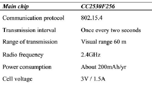
[image:3.595.309.560.294.437.2]The above figure shows the active RFID tag used in this paper. A radio frequency identification system uses tag, attached to the object to be identified. Two-way radio transmitter-receivers called interrogators or readers send a signal to the tag and read its response. An active RFID tag has an on-board battery and periodically transmits its ID signal. This tag is facilated with ZigBee for wireless communication with the host, and it is equipped with a cell, it can keep working for more than three years in SLEEP energy saving mode. Table 1 shows the specifications of active RFID tag.
Table: Specification of active RFID tag
Figure 4 shows the ZigBee positioning reader. The ZigBee and RFID are two wireless technologies that have developed hosts of application independent of each other. The ZigBee positioning reader has router function, and it is one node of ZigBee router. The ZigBee positioning reader is placed in small areas of the monitoring range, and it is communicating with the monitoring centre via ZigBee router.
Figure4.2: Active RFID-ZigBee
[image:3.595.319.546.581.710.2]© 2017, IRJET | Impact Factor value: 5.181 | ISO 9001:2008 Certified Journal | Page 3327
RS232 interface used for wireless transmission. ZigBee is a new and popular protocol for wireless communication because of its low power assumption, large network capacity and the ability to organize a network automatically [5]. Figure 5 shows the ZigBee-RS232 wireless communication module (Coordinator) used in this paper. This system receives the information sent from the active RFID ZigBee positioning reader, and converts it into RS232 signal to communicate with the monitoring host. The maximum transmission distance is generally 200m.
Figure4.3: ZigBee-RS-232 wireless communication module
RS-232 ISA standard for serial communication transmission of data. It formally defines the signal connecting between Data circuit-terminating equipment or data communication equipment, such as a modem. RS-232, when compared to other serial interfaces such as RS-422, RS-485 and Ethernet, is hampered by low transmission speed, short maximum cable length, large voltage swing, large standard connectors, no multipoint capability and limited multi-drop capability. In latest personal computers, USB has displaced RS-232 from most of its peripheral interface roles.
SOFTWARE INTERFACE
This system builds a graphical man-machine interface. Figure6 shows the software system interface. This system consists of three parts, including control interface, patient information and emergency display field and positioning display menu. By using this system, it is possible to assist the patient personnel and also this system takes care of the patients.
F igure4.4: Medical care positioning system
interface
© 2017, IRJET | Impact Factor value: 5.181 | ISO 9001:2008 Certified Journal | Page 3328
MICRO CONTROLLER ARCHITECTURE
Figure5.1:Internal architecture of a PIC16f877A Chip
PIC (Programmable Interface controllers) microcontrollers is the smallest microcontroller in the world that can be programmed to carry out a very large range of tasks. This microcontroller is found in many electronic devices such as phones, computer control systems, alarm systems, embedded systems, etc. PIC microcontroller consists of registers and stack. These registers is used for Random Access Memory (RAM) and stack saves the return addresses respectively. The main features of PIC microcontrollers are RAM, flash memory, Timers/counters, EEPROM, I/O Ports, USART, CCP (Capture/Compare/PWM module), SSP, Comparator, ADC (Analog to digital converter), PSP (parallel slave port), LCD and ICSP(in circuit serial programming).
MEMORY ORGANISATION OF PIC16F877A
The memory of a PIC 16F877 chip is divided into three sections. They are
1. Program memory 2. Data memory and 3. Data EEPROM
Program memory
Program memory contains the programs that are written by the user. The program counter executes these stored commands one by one. Usually PIC 16F877A devices have 31-bit wide programme counter that is capable of addressing 8Kx14 bit program memory space. This memory primarily used for storing the programs that are written to be used by the PIC. These devices also have 8K*14 bits of flash memory that can be electrically erasable. Each time we write a new program to the controller.
Figure5.2: PIC 16F877A program memory
Data memory
© 2017, IRJET | Impact Factor value: 5.181 | ISO 9001:2008 Certified Journal | Page 3329 Figure5.3: Data memory organization
Data EEPROM
The data EEPROM and Flash program memory is readable and writable during operation this memory is indirectly mapped in the register file space. Instead, it is indirectly addressed through the special functions registers. The EEPROM data memory gives single-byte read and writes. The Flash program memory gives only single word reads and four-word block writes. Program memory write operations automatically which perform an erase-before write on blocks of four words.
CONCLUSION
In this paper, we used RFID, ZigBee technology and graphical man-machine interface. RFID can transmit identification data through radio wave without battery. ZigBee technology monitoring production environment explosive remote monitoring system. From the test result we proved that nursing personnel can reduce the careless mistakes in medical treatment by using medical care positioning system. When a patient pressed the emergency call button, an active tag send a distress signal to the host side, this signal showsthat
patient is in emergency, so that the nursing personnel can provide rescue in time.
REFERENCE
[1] H.-L. Shieh, S.-F. Lin, W.-S. Chang, “RFID medicine management system”, in Proc. ICMLC2012, July, 15-17, 2012 , pp. 1890-1894.
[2] Roy Want, “An Introduction to RFID Technology”, IEEE Pervasive Computing, vol.5 no.1, p.25, Jan., 2006. [3] Yang Li, Ke Zhang, “Research on Application of ZigBee Technology” in Flammable and Explosive Environment, Wireless Sensor Network, pp. 467-471, 2010.
[4] ZigBee Alliance (2009), “ZigBee Wireless Sensor Applications for Health, Wellness and Fitness,” Available: https://docs.zigbee.org/zigbee-docs/dcn/09-4962.pdf.