© 2016, IRJET | Impact Factor value: 4.45 | ISO 9001:2008 Certified Journal | Page 811
Smart Switching of Multi-terminal Hybrid DC Power Based on Load
R.Suguna, R.Madhan, C.David Raja, R.Ramesh
Assistant Professor, Veltech Hightech Dr.Rangarajan Dr.Sagunthala Engineering College
UG Student, Veltech Hightech Dr.Rangarajan Dr.Sagunthala Engineering College
---
ABSTRACT : A fault protection and location method for a dc bus micro grid system is presented in this paper. If a fault causes the dc bus to de-energize completely, it makes locating faults very difficult. The proposed algorithm can be implemented and executed by an intelligent electrical device for an individual node. The bus was segmented into overlapping nodes and links with circuit breakers (CBs) to isolate the segment in the event of a fault. Backup protection is implemented for circuit breaker failures to improve system reliability. This power can also be used for a pilot test before main CB reclosing to avoid system issues that can be expected when the reclosing fails due to a permanent fault in this paper, we investigate an event-based protection scheme for a multi-terminal dc power system, which includes hybrid energy resources and various loading schemes. The proposed protection scheme transfers less data when compared with commonly used data based protection methods, and do not require high-speed communication and synchronization. Each protection unit is able to autonomously identify the type of event using the current derivative fault identification method, employing artificial inductive line impedance. In order to accurately set the protection relays, detailed fault current analysis considering low pass resistor capacitor filter effects are presented. The decision for fault isolation is made based on the unit judgment and the data received through high-level data communication from other inter-connected units. The performance of the proposed protection scheme was evaluated under different dc feeder and bus faults and its shows that this
scheme is able to accurately identify the type of fault, isolate the faulted area, and restore the system quickly while limiting the load voltage drop to its preset limit. The result has been evaluated using the PROTEUS DESIGN SUIT simulation software.
Keywords: DC ring bus, Hybrid DC power, Smart Relay, fault location, etc.,
1.
INTRODUCTION
© 2016, IRJET | Impact Factor value: 4.45 | ISO 9001:2008 Certified Journal | Page 812 reliable power with higher efficiency through the
implementation of the power electronic converters and the storage energy devices. In various applications, such as telecommunication systems, shipboard and spacecraft, and distribution systems involving a large number of electronic loads and data centres, dc architectures provide a more effective solution for electric power distribution. However, there is a widespread concern over the means used to protect the system against short circuit faults, especially in multisource distribution systems and multi-terminal dc lines. The protection of a power system that includes a large number of buses and feeders can be categorized into the based and event-based protection schemes. In the data-based protection method, electric variables such as the converter current or the bus voltage are measured and sent to the interconnected protection unit to execute fault identification algorithms. In the event-based protection scheme, the measured fault parameters are locally analyzed to classify the type of event. Then, the event judgment is sent to other interconnected protection units through high-level data communication.
2.
PROPOSED SYSTEM
An event-based protection scheme for a multi-terminal dc power system, which includes hybrid energy resources and various loading schemes. Each protection unit is able to autonomously identify the type of event using the current derivative fault identification method, employing artificial inductive line impedance. In order to accurately set the protection relays, detailed fault current analysis considering low pass resistor capacitor filter effects are presented. The decision for fault isolation is made based on the unit judgment and the data received through high-level
data communication from other interconnected units. The
main aim of this project is fault protection and location method for DC bus micro grid system along with MPPT techniques. The main goal of the proposed system is to detect and isolate the fault in DC BUS without de-energize entire system and identify the fault location. In fault occurring time we can manipulate the power in the circuit. To the load depends upon the power in coming to the load. Power management to the load depends upon the power.
Fig 2.1.Block Diagram Of Multi-terminal hybrid DC
power system with Smart relay
[image:2.612.328.518.253.461.2]© 2016, IRJET | Impact Factor value: 4.45 | ISO 9001:2008 Certified Journal | Page 813
3. SIMULATION SOFTWARE
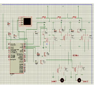
[image:3.612.38.234.151.326.2]3.1. SIMULATION DIAGRAM
Fig 3.1. Simulation Diagram
DC BUS RING SIMULATION PROGRAM
#include <16f877a.h> #use delay(clock=4000000)
#use rs232(baud=9600,xmit=pin_c6,rcv=pin_c7) void main()
{
unsigned int a=0,b=0,c=0; unsigned int x=0,y=0,z=0; unsigned int i=0,j=0,k=0; unsigned int v=0; set_tris_b(0); output_b(0);
setup_adc(ADC_CLOCK_INTERNAL); // clock frer
setup_adc_ports(2); // indicates what are the analog ports printf("*****welcome****\n\r");
printf("*****DC BUS RING****\n\n\n"); delay_ms(1000);
while(1) {
set_adc_channel(0); delay_ms(10); a=read_adc(); x=a/21.25; if(x>1) {
x=8+x; i=1;
printf("S1 = %u ",x); output_low(pin_b2); v=v+x;
} else { i=0;
printf("S1 = LOW"); output_high(pin_b2); }
set_adc_channel(1); delay_ms(10); b=read_adc(); y=b/21.25; if(y>1) { y=8+y; j=1;
printf("S2 = %u ",y); output_low(pin_b3); v=v+y;
} else { j=0;
printf("S2 = LOW"); output_high(pin_b3); }
set_adc_channel(2); delay_ms(10); c=read_adc(); z=c/21.25; if(z>3) { z=8+z; k=1;
printf("S3 = %u \n\r",z); output_low(pin_b4); v=v+z;
} else { k=0;
© 2016, IRJET | Impact Factor value: 4.45 | ISO 9001:2008 Certified Journal | Page 814 output_high(pin_b4);
}
printf("DC BUS Total Voltage = %u \n\r",v); v=0;
if((i==1) && (j==1) && (k==1)) {
output_high(pin_b0); output_high(pin_b1);
printf("Load 1 = ON Load 2 = ON\n\r\n\r\n\r"); }
else if((i==0) && (j==0) && (k==0)) {
output_low(pin_b0); output_low(pin_b1);
printf("Load 1 = OFF Load 2 = OFF\n\r\n\r\n\r"); }
else {
output_low(pin_b0); output_high(pin_b1);
printf("Load 1 = ON Load 2 = OFF\n\r\n\r\n\r"); }
3 OUTPUT OF SIMULATION
© 2016, IRJET | Impact Factor value: 4.45 | ISO 9001:2008 Certified Journal | Page 815
CONCLUSION
To overcome the DC bus failure we introduced the ring bus method. We additionally added a smart controller unit which maintains the power management and load management in DC ring bus through smart relay unit. An event-based protection scheme for a multi-terminal hybrid dc micro-grid was investigated. The notional micro-grid considered for this paper was implemented in hardware and its dynamic operation was experimentally tested. Also, for dynamic operation and fault study, an accurate model of this micro-grid was implemented in the Proteus design suit environment and evaluated using the experimental test results and the analytical calculations. In the proposed protection strategy developed here, each power unit was able to identify the type of event autonomously. Since high-level data communication was utilized, the protection system did not require high-speed communication and synchronization. The performance of the grid and the proposed protection scheme were evaluated using analytical fault current calculation and a simulation model. The results
confirm that the proposed protection scheme is fast and accurate and the grid can ride-through the fault uninterrupted. The detailed analytical analysis given in this paper provided essential guidelines to set the protection relays for an event-based protection scheme. This can be utilized in multi-terminal dc micro-grid, such as renewable energy distributed generation micro-grids, data centres, or shipboard power systems where diagnosing and self-reconfiguring capability is in high demand.
REFERENCES
[1] M. Farhadi and O. Mohammed, “Real-time operation and harmonic analysis
of isolated and non-isolated hybrid DC microgrid,” IEEE Trans. Ind.
Appl., vol. 50, no. 4, pp. 2900–2909, Jul./Aug. 2014. [2] M. Farhadi and O. Mohammed, “Adaptive energy management in redundant
hybrid DC microgrid for pulse load mitigation,” IEEE Trans. Smart
Grid, vol. 6, no. 1, pp. 54–62, Jan. 2015.
[3] A. Mohamed, C. Cossio, T. Ma, M. Farhadi, and O. Mohammed,
“Operation and protection of photovoltaic systems in hybrid AC/DC
smart grids,” in Proc. IEEE 38th Annu. Conf. IEEE Ind. Electron. Soc. (IECON), Montreal, QC, Canada, 2012, pp. 1104–1109. [4] M. Farhadi, A. Mohamed, and O. Mohammed,
“Connectivity and bidirectional
energy transfer in DC microgrid featuring different voltage characteristics,” in Proc. IEEE Green Technol. Conf., Denver, CO, USA,
2013, pp. 244–249.
[5] J. Brozek, “DC overcurrent protection—Where we stand,”
© 2016, IRJET | Impact Factor value: 4.45 | ISO 9001:2008 Certified Journal | Page 816
Ind. Appl., vol. 29, no. 5, pp. 1029–1032, Sep./Oct. 1993. [6] IEEE Recommended Practice for 1 kV to 35 kV Medium-Voltage DC
Power Systems on Ships, IEEE Standard 1709-2010, Nov. 2010.
[7] Recommended Practice for Emergency and Standby Power Systems
for Industrial and Commercial Applications, IEEE Standard 446-1995,
Jul. 1996.
[8] D. Salomonsson, L. Soder, and A. Sannino, “Protection of low-voltage
DC microgrids,” IEEE Trans. Power Del., vol. 24, no. 3, pp. 1045–1053,
Jul. 2009.
[9] P. Cairoli, I. Kondratiev, and R. A. Dougal, “Coordinated control of
the bus tie switches and power supply converters for fault protection
in DC microgrids,” IEEE Trans. Power Electron., vol. 28, no. 4, pp. 2037–2047, Apr. 2013.
[10] L. Tang and B. T. Ooi, “Locating and isolating DC faults in multiterminal
DC system,” IEEE Trans. Power Del., vol. 22, no. 3, pp. 1877–1884, Jul. 2007.
[11] Y. Pradeep, S. Khaparde, and R. Joshi, “High level event ontology
for multiarea power system,” IEEE Trans. Smart Grid, vol. 3, no. 1,
pp. 193–202, Mar. 2012.
[12] F. Lotfifard, H. Seifi, and M. K. Sheikh-El-Eslami, “An economic-based
special protection system in a restructured environment,”
Elect. Power
Compon. Syst. J., vol. 41, no. 15, pp. 1536–1554, 2013.
[13] A. Nejadpak and O. A. Mohammed, “Physics-based modeling of power
converters from finite element electromagnetic field computations,”
IEEE Trans. Magn., vol. 49, no. 1, pp. 567–576, Jan. 2013. [14] A. Nejadpak, A. Sarikhani, and O. A. Mohammed, “Analysis of radiated
EMI and noise propagation in three-phase inverter system operating
under different switching patterns,” IEEE Trans. Magn., vol. 49, no. 5,
pp. 2213–2216, May 2013.
[15] S. R. Velazquez, T. Q. Nguyen, and S. R. Broadstone, “Design of hybrid
filter banks for analog/digital conversion,” IEEE Trans. Signal Process.,
vol. 46, no. 4, pp. 956–967, Apr. 1998.
[16] IEEE Standard for Terminology and Test Methods for Analog-to-Digital
Converters, IEEE Standard 1241-2010, Jan. 2011. [17] J. Cao and A. Emadi, “A new battery/ultracapacitor hybrid energy
storage system for electric, hybrid, and plug-in hybrid electric vehicles,”
IEEE Trans. Power Electron., vol. 27, no. 1, pp. 122–132, Jan. 2012.
[18] V. Musolino, L. Piegari, and E. Tironi, “New full-frequency-range supercapacitor
model with easy identification procedure,” IEEE Trans. Ind. Electron., vol. 60, no. 1, pp. 112–120, Jan. 2013.
[19] R. A. Dougal, L. Gao, and S. Liu, “Ultracapacitor model with automatic
order selection and capacity scaling for dynamic system simulation,”
© 2016, IRJET | Impact Factor value: 4.45 | ISO 9001:2008 Certified Journal | Page 817 [20] S. Buller, E. Karden, D. Kok, and R. W. De Doncker,
“Modeling the
dynamic behavior of supercapacitors using impedance spectroscopy,”
IEEE Trans. Ind. Appl., vol. 38, no. 6, pp. 1622–1626, Nov./Dec. 2002.
[21] Z. M. Salameh, M. A. Casacca, and W. A. Lynch, “A mathematical
model for lead-acid batteries,” IEEE Trans. Energy Convers.,
vol. 7,
no. 1, pp. 93–98, Mar. 1992.
[22] C. M. Shepherd, “Design of primary and secondary cells—Part 2. An
equation describing battery discharge,” J. Electrochem. Soc.,
vol. 112,
pp. 657–664, Jul. 1965.
[23] P. Pozzobon, “Transient and steady-state short-circuit currents in rectifiers
for DC traction supply,” IEEE Trans. Veh. Technol., vol. 47, no. 4,
pp. 1390–1404, Nov. 1998.
[24] A. Agarwal and J. H. Lang, Foundations of Analog and Digital Circuits.
San Francisco, CA, USA: Morgan Kaufman, 2005.
[25] A. Greenwood, Electrical Transients in Power Systems. Hoboken, NJ,
USA: Wiley, 1991.
[26] J. Carr and R. V. Jackson, “Frequency domain analysis applied to digital
transmission line protection,” IEEE Trans. Power App. Syst.,
vol. 94,