© 2017, IRJET | Impact Factor value: 5.181 | ISO 9001:2008 Certified Journal | Page 519
Modeling and Analysis of Temperature Distribution in the Oven using
Computational Fluid Dynamic (CFD)-A Review
Vaibhav C. Dhanuskar
1, Dr. P. R. Pachghare
21 P.G. Student, Department of Mechanical Engineering Govt Engineering College, Amravati, Maharashtra, India 2 Asst. Professor, Department of Mechanical Engineering Govt Engineering College, Amravati, Maharashtra, India
---***---Abstract -
In this paper, the study is focus on the modelingand analysis of temperature distribution in the oven using Computational Fluid Dynamic (CFD) techniques. In this paper, the CFD analysis of different ovens with varying parameter is presented. The various powder coating processes are studied. The temperature and pressure distribution in the oven plays a dominating role in the product quality. The uniform temperature and pressure distribution is achieved using geometry modification. The effect of perforated inlet to temperature and pressure distribution on the oven is analyzed using CFD simulation.
Key Words: PVDF-Poly Vinylidene Fluoride, TGIC, Powder
Coating, CFD etc.
1. INTRODUCTION:
A coating is a covering which is applied on to the surface of an object which is referred as the substrate. There are two main types of powder coating processes.
Liquid Coating Technology (Wet) Powder Coating Technology (Dry)
The use of powder coating as a finishing process has grown significantly in the past several years. More and more finishing engineers have turned to powder coating as a way to produce a high-quality finish while increasing production, cutting costs, and complying with increasing environmental pressures. Also, ongoing technological breakthroughs are continually knocking down the few barriers that hindered powder coatings ability to grow in the market. In fact, powder coating now constitutes 15% of the finishing market where it competes directly with traditional liquid finishes. It covers over 10% of the total industrial finishing market.
1.1 Types of Powder Coating
Today, powder coatings are available to the industrial finisher in two major types viz. thermoplastics and thermosetting.
1.1.1 Thermoplastic Powder Coating.
Thermoplastic coatings do not chemically on the application of heat, but they melt and flow out onto the substrate and continue to have the same chemical
composition when it solidifies on cooling. The thickness obtained from these coating films is typically around 250 microns or more. Thermoplastic powder coatings are based on thermoplastic resins of high molecular weight. Typical examples of thermoplastic powder are:
Polyethylene: Polyethylene powders were the first thermoplastic powder coatings offered to industry. Polyethylene provides coatings of excellent chemical resistance and toughness with outstanding electrical insulation properties.
Polypropylene: As a surface coating, poly propylene offers many of the useful properties it has as a plastic material. Natural polypropylene is inert in nature, it shows very little tendency to adhere to object or other substrates. Nylon: Nylon powders are almost all based on type 11 nylon resin and offer tough coatings that have excellent abrasion, wear, and impact resistance with a low coefficient of friction when applied over a suitable primer. A most interesting use of nylon powder coating is in the field of mechanical design.
Polyvinyl: Polyvinyl chloride powder coatings have good exterior durability and provide coatings with a medium-soft glossy finish. They bond well to most metal substrates when applied over suitable primer. These coatings will withstand the stress of metal fabrication operations such as bending, embossing, and drawing.
PVDF (Poly-Vinylidene Fluoride): PVDF based coating materials have excellent weathering characteristics. They also have excellent resistance to chemicals with the exception of hydrocarbon solvents. They are used to coat piping and valves used in chemical process industries. Usually, a chromate primer is recommended.
1.1.2. Thermosetting Powder Coating:
© 2017, IRJET | Impact Factor value: 5.181 | ISO 9001:2008 Certified Journal | Page 520 characteristics of these resin systems, they can produce
thin paint-like surface coatings in the 1 to 3 mil (approximately.025 to .076 mm) range with properties equivalent and sometimes superior to the coatings produced by the liquid compliance technologies. The generic types of resins used in thermosetting powder coatings are as follows.
Epoxy powders: Epoxy powders can be formulated to give high gloss and smooth coatings with excellent adhesion, flexibility and hardness as well as solvent and chemical resistance. The main deficiencies are their poor tolerance to heat and light as well as their pronounced tendency to yellow at elevated temperatures and exposure to diffused day light.
Acrylic powders: Polyester powders are widely used in surface coatings. They have good gloss and color retention on exterior exposure as well as heat and alkali resistance. Polyester powders: Polyester powders general performance can be categorized between epoxy and acrylic powders. They have excellent durability and a high resistance to yellowing under ultra-violet light. Most powder coatings used on buildings today are based on linear polyesters cross linked with TGIC. Today modern polyester powders are TGIC-free
Epoxy polyester hybrid powders: Epoxy polyester hybrid powders are epoxy powders by origin containing a high percentage of special polyester resin (sometimes exceeding 50%). These Epoxy polyester hybrid powder have properties similar to the epoxy powders, however, their additional advantage is that they have improved resistance to over bake yellowing and improved weather ability. Hybrid powders are now regarded as the main backbone of the powder coatings industry.
Polyurethane powders: Polyurethane powders provide good all-round physical and chemical properties as well as giving good exterior durability. New polyester. Now entering the marketplace are polyester powder coatings based on new crosslinking chemistries. They are endowed with excellent mechanical properties such as high film thickness, good edge coverage, and dielectric resistance. Their appearance and properties are similar to TGIC (carboxyl) polyesters. This type of polyester powder is ideally suited for coating air conditioner cabinets, transformers Silicone acrylics. A recently introduced class of silicone powder coating material can withstand operating temperatures from 400°F (204°C) to over 1,000"F (538°C) and has found applications in areas from food contact cookware to engine exhaust systems.
1.2 Powder Coating Process Fundamentals
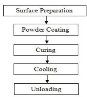
[image:2.595.354.498.95.255.2]A process flow block-diagram for a powder coating process is given in the following Figure.
Fig 1.1: Process Flow Block-Diagram of Powder Coating.
1.2.1 Surface Preparation
Removal of any impurities like oil, dirt, lubrication greases, metal oxides, welding scale etc. is necessary before the powder coating process. It can be done either by chemical or mechanical methods. The selection of the proper method is dependent on the size of particle and the material which needs to be powder coated, the type of impurities to be removed and the performance requirement of the finished product. There are two main types of surface preparation.
a. Mechanical Cleaning Process b. Chemical Cleaning Process
1.2.2 Powder Coating.
In various powder coating requirements, powder is charged electrostatically through spray guns and sprayed onto the work piece. Other methods include fluidized bed dipping, powder cloud and electrostatic brush application. Most of the methods used fall into one of the following processes.
1. Electrostatic Spray Process
a. Corona spray gun
b. Tribo spray gun
2. Fluidized Bed Process.
The selection of the application method for a processing plant is often guided by particular needs being identified via a market survey and plant management considerations such as follows.
a. Nature and size of the parts to be coated b. Specification of the coating film
c. Processing quantities per order and per year
d. Powder material
e. Available processing surface and volume
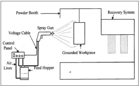
1.2.2.1. Electrostatic Spray Process
© 2017, IRJET | Impact Factor value: 5.181 | ISO 9001:2008 Certified Journal | Page 521 application booth. It is delivered with the help of powder
pump and transport by the air flow system to the electrostatic spray gun. The particles are charged on emission from the gun and with the help of the transport air move in the direction of the grounded work-piece. when the charged particles is sprayed onto the grounded work piece, electrostatic attraction causes the particles to deposit and adhere to the work piece. There are two distinct methods for building up the charge on the particle surfaces.
[image:3.595.37.270.346.489.2]In Corona charging method, high voltage generator (80-100 kv) is used to bring an electrostic charge (mostly negative) onto the powder particles through the intermediate process of creating oxygen ions. The Tribo method, the electrostatic charge (positive particles) is built up by the particles rubbing with increased velocity along a specially selected material (e.g. Teflon) inside the spray gun for sufficient time, without the use of a high voltage generator. Both spraying methods have their own typical powder cloud build up.
Fig 1.2: Electrostatic Spray Application System
1.2.2.2. Fluidized Bed Process
Although the electrostatic spray method is the primary process for powder application, we will also be covering the fluidized bed coating method as one of the alternative coating processes. In the case of thermosetting powders, this is almost exclusively carried out with epoxy resin based powders for large work-pieces such as pipe line valves, fencepost etc. or small articles from the electronic industry for insulation. The majority of fluid bed coating is used for thermoplastic application. These coatings mainly provide a thick tough coating film with excellent corrosion resistance properties and very good mechanical, electrical insulation and chemical properties. Fluid bed coating does not need electrostatic charging of the powder particles and can take place with either pre or post-heated objects. When electrostatic charging, a fluid bed safety measures should be taken toavoid risk of explosion. The fluid bed is usually constructed as a container, the bottom part of which is an air plenum chamber and the top part is a porous plate. The plate is covered with the certain volume of powder, which is fluidized by air from below. The resulting electrically charged cloud of powder is attracted
to and deposits on an object when it is hung in the powder cloud.
1.2.3. Curing Oven
To polymerize the powder applied to the substrate we must heat both to a high temperature for a few minutes. This is the curing process. As powder coatings do not contain solvents (unlike liquid coatings) a flash zone is not required in the curing oven. The volume of exhaust gases is also substantially lower which can also substantially lower operational costs. The formulation of the powder coating material determines to a large extent the curing time and temperature of the coated object. It also result in the specified film properties on the material..
1.2.3.1. Convection oven:
© 2017, IRJET | Impact Factor value: 5.181 | ISO 9001:2008 Certified Journal | Page 522 Fig 1.2: Cure Index [3]
1.2.3.2. Infra-Red oven:
Infrared oven uses radiant energy to heat a product through electromagnetic waves. Infrared heating works very quickly. There are basic three types of emitters - short emitters, medium emitters and long wave length emitters. Their main performance differences are operating temperature(some 2000, 1050 and 600°C respectively) and radiation efficiency (80, 60 and 50% respectively).Higher temperatures result in faster heating rates and a lower efficiency which results in a higher loss of energy through convection mode of heat transfer.
1.2.3.3. Dual or combination oven:
Both infra-red and convection are applied. In the infrared section the powder film is melted to avoid powder being blown off in the convection section where additional time is available to complete the entire cross linking process.
1.2.3.4. Induction oven:
Heat is generated in the metal object through induction of eddy currents. The advantage being, as with infrared, the powder coating can start reacting before contact with gas combustion components can take place. Medium temperature radiation offers the most effective source of heat energy for curing the thermosetting powders. Gas fired emitter panels present a panel surface temperature of 900°C. Electric panels give a surface temperature of approximately 800°C. The work-pieces should be maintained at a distance of approximately 300mm from the emitter panels. Substrates coated with darker color powder absorb more infra-red radiation, while objects with light colored powder do not heat up as quickly. It is therefore recommended that each individual powder is tested in combination with the curing oven to evaluate the curing performance.
2. LITERATURE REWIEV
P.S. Mirade et. al.[1] had studied the “Characterization and CFD modeling of air temperature and velocity profiles in an
industrial biscuit baking tunnel oven”. In this paper He discussed application of a CFD approach to predict the air temperature and velocity profiles inside the baking chamber of an industrial indirect gas-fired tunnel oven used for biscuit baking. He used two three-dimensional CFD models (one not covering the conveying band of biscuits and the other including it) to describe the complex air circulation resulting from the mechanisms of air input and exit at the ends of the oven and of air extraction through the different extraction points located along the oven length. Comparison of numerical results with experimental measurements shows a fairly close agreement in the qualitative prediction and a few inaccuracies in the quantitative prediction of the air temperature profiles within the baking chamber. To make reliable measurements of air velocities in baking ovens and easier comparisons with numerical results, sensors suitable for measuring low velocities in very hot atmospheres are needed.
Nantawan Therdthai et. al. [2] studied the CFD modeling and simulation of an industrial continuous bread baking oven using two dimensional model. In this He studied an industrial continuous bread baking oven, bread is travelling inside the oven chamber and it is the oven temperature distribution in this whole travelling period that dominates the product quality variations. To establish a numerical model covering the temperature distribution of the whole oven chamber, he used computational fluid dynamics (CFD) method. A two-dimensional CFD model was prepared to simulate the pattern of temperature distribution and airflow pattern due to the convection and radiation mode of heat transfer. With several oven operating parameters including heat supply and fan volume, the heat distribution trend in the oven was satisfactorily simulated. This provided constructive information to achieve the optimum baking temperature profile by manipulating energy supply and airflow pattern. Based on the results obtained from simulation, the emitters, positioning of the controller sensors were investigated through a sensitivity study. He also found that the simulation results could also be used to modify the oven configuration for better heat distribution.
© 2017, IRJET | Impact Factor value: 5.181 | ISO 9001:2008 Certified Journal | Page 523 These results confirmed that the IR oven has better efficiency
than the other traditional convection oven particularly for large objects having high emissivity. In terms of heat up rate, the infrared oven also exhibited better performance with a temperature boost about 40-fold faster than convection heat transfer depending on the thickness. For example, thin material took 2.90K/s and 0.05K/s, while 47.83K/s and 1.08K/s for optically thick media in radiation and convection respectively. The different pigments affect absorption and scattering in IR-radiation. Black presented highest temperature and heat up rate followed by blue, red and white respectively. The different between highest (black) and lowest (white) mean temperature is 0.85% and 0.35% for steel and MDF. However, the relationship between the temperature and emissivity seems relevant with the theory that high emissivity leads to higher better heating performance. With regard to computational results, it can clearly discriminate between the traditional convection oven and the infrared oven which the latter seems more energy efficient. Moreover, mode simulation can indicate some process heating problems on curing powder coated low-conductivity material such as cracks on the edge in powder coated MDF. Finally, the results can provide a baseline for process engineer to design the infrared process heating and may also be used to retrofit existing ovens for better thermal distribution.
Andrew Lee [5] studied “Numerical Investigation of the Temperature Distribution in an Industrial Oven”. A numerical investigation was performed on an industrial oven using a Computational Fluid Dynamics technique. The Results obtained from the numerical investigation of oven at Orford Refrigeration proved that oven has predominantly uniform in temperature distribution. It appears that, the majority of the oven is within the range of between 314 to 348 degrees Celsius. The temperature distribution inside the oven was found to be related to the velocity. The variation in temperature seemed to follow the velocity contours. From the results collected, the problem areas inside the industrial oven have be identified as cold spots, air flow through the perforations and circulation zones.
Pragati Kaushal and Sharma HK [7] have studied concept of (CFD) and its Applications in Food Processing Equipment Design. CFD can be used as a tool for design of food processing equipment. Its applications include the various processes such as cleaning of storage tanks, crystallization, conventional cyclones, drying, sterilization, crystallization, mixing and refrigeration, fermentation, baking etc.
Zinedine Khatiret. Al. [8] have studied the application of computational fluid dynamics (CFD) and oven design optimization in the British bread-baking industry and reduce
the effective baking time of the bread, and hence improve the energy efficiency of the process. Computational Fluid Dynamics (CFD) is combined with an optimization framework to develop a promising tool for the rapid generation of forced convection oven designs. A design parameterization of a three dimensional generic oven model is carried out to enable optimization, for a wide range of oven sizes and flow conditions, to be performed subject to appropriate objective functions measuring desirable features such as, for example, temperature and pressure uniformity throughout the oven region. A series of optimizations for various oven sizes and flow conditions are performed using a genetic algorithm with responses calculated from the surrogates. This approach results in a set of optimized designs, from which appropriate oven designs for a wide range of specific applications can be inferred. It is found that for the particular oven design and objective function under investigation, the optimized design is obtained with a dimensionless nozzle-to-surface distance H/D = 6.82, nozzle diameter D = 20mm and an operating jets velocity unoz= 38.12 m/s under baking temperature of 240oC.Under these conditions baking time can be reduced by 5-10%,subsequently resulting in energy savings of a similar magnitude. The use of CFD within an optimization framework, where a Suitable objective function is chosen to represent the desired outcome, allows efficient use of computational resource.
Verboven et al.[11], presents the validation of air flow inside a forced convection, electrical oven. This paper discusses a 3-D model using the fan model and turbulence model. Rokni [12] discusses fully developed turbulent flow in ducts, over a large range of Reynolds numbers. This process combines the viscosity model with the “two-equation” model, the model is also valid over a wide range of Prandtl numbers and different fluids to obtain an algebraic flux model with variable diffusivity.
Jones [13], presents a relevant topic on the convection flow in vertical parallel walls. The paper provides a numerical solution for the situation and provides results for the velocity profile inside the walls, local Nusselt numbers, average temperatures, friction factors and areas of circulation that occur.
© 2017, IRJET | Impact Factor value: 5.181 | ISO 9001:2008 Certified Journal | Page 524
4. CONCLUSIONS
In this review paper, the research done by various researchers to analyze different types of oven by using computational fluid dynamics (CFD) is presented. A Two Dimensional and Three Dimensional CFD analysis plays a vital role in oven analysis. CFD is a promising computational tool for optimization of oven design and energy consumed. The IR oven has better efficiency than the other traditional convection oven particularly for large objects having high emissivity.
REFERENCES
[1]. “Characterization and CFD modeling of air temperature and velocity profiles in an industrial biscuit baking tunnel oven”, P.S. Mirade, J.D. Daudin, F. Ducept, G. Trystram, J. Clement,/ Food Research International 37 (2004), 1031– 1039.
[2]. “Two-dimensional CFD modeling and simulation of an industrial continuous bread baking oven”, Nantawan Therdthai ,Weibiao Zhou, Thomas Adamczak,/ Journal of Food Engineering 60 (2003), 211–217.
[3]. “Understanding gas fired convection curing equipment for powder coating”, Rodger Talbert,/Powder Coating, (Nov 1994),35-41.
[4]. “Computational Fluid Dynamic (CFD) Modeling and alidation of Temperature Distribution in the Infrared Oven”, Pumphruk Satit ,/ School of Engineering and Physical Sciences, Heriot-Watt University, Edinburgh, UK.
[5]. “Numerical Investigation of the Temperature Distribution in an Industrial Oven”, Andrew Lee,/ University of Southern Queensland.
[6]. “Assessment of simplified thermal radiation models for engineering calculations in natural gas-fired furnace”, D.A. Kontogeorgos, E.P. Keramida, M.A. Founti,/ International Journal of Heat and Mass Transfer 50 (2007) , 5260–5268. [7]. “Concept of Computational Fluid Dynamics (CFD) and its Applications in Food Processing Equipment Design”, Pragati Kaushal and Sharma HK,/ Journal of Food Process Technology, Volume 3 Issue 1,2012.
[8]. “The Application Of Computational Fluid Dynamics (CFD) And Oven Design Optimization In The British Bread-baking Industry”, Zinedine KHATIR et. al,/ 8th International Conference on CFD in Oil & Gas, Metallurgical and Process Industries SINTEF/NTNU, Trondheim Norway, 21-23 June 2011.
[9]. “The Powder Coaters Manual”, Roger Talbert,/pg 1-98. [10]. “Complete Guide To Powder Coatings”, World Leader In Powder Technology,/ Issue1, Nov 1999.
[11]. “Computational fluid dynamics modelling and validation of the temperature distribution in a forced convection oven”, Verboven, P et. al. 199, Journal of Food Engineering, vol. 43,no. 2, pp. 61-73.
[12]., “Investigation of a Two-Equation Turbulent Heat Transfer Model Applied to Ducts”, Rokni, M & Sunden, B 2003 Journal of Heat Transfer, vol. 125, no. 1, pp.194-200. [13]. Jones, A & Ingham, D 1993, “Combined convection flow in a vertical duct with wall temperatures that vary linearly with depth”, International Journal of Heat and Fluid Flow, vol. 14, no. 1, pp. 37-47.
![Fig 1.2: Cure Index [3]](https://thumb-us.123doks.com/thumbv2/123dok_us/8162868.806301/4.595.35.263.94.227/fig-cure-index.webp)
