Projector-Camera Systems
David Molyneaux1, Hans Gellersen1, Gerd Kortuem1 and Bernt Schiele2
1Computing Department, Lancaster University, England 2Computer Science Department, Darmstadt University of Technology
1{d.molyneaux, hwg, kortuem}@comp.lancs.ac.uk 2[email protected]
Abstract. In this paper we present a new approach for cooperation between mobile smart objects and projector-camera systems to enable augmentation of the surface of objects with interactive projected displays. We investigate how a smart object’s capability for self description and sensing can be used in cooperation with the vision capability of projector-camera systems to help locate, track and display information onto object surfaces in an unconstrained environment. Finally, we develop a framework that can be applied to distributed projector-camera systems, cope with varying levels of description knowledge and different sensors embedded in an object.
Keywords: Cooperative Augmentation, Smart Objects, Projector-Camera Systems
1 Introduction
The interest in embedding sensing, communication and computation in everyday physical artefacts is growing. Such smart objects are expected to bridge the gap between the physical and digital world, and become part of out lives in economically important areas such as retail, supply chain or asset management [29,30,31] and safety critical situations in work places [10]. A challenge for the design of such smart objects is to preserve their original appearance, purpose and function, thus exploiting natural interaction and a user’s familiarity with the object [12]. Consequently adding output capability to objects is difficult, as embedding displays would fundamentally change an objects appearance. Mobile objects are also typically constrained in terms of power, weight and space availability. However, the recent availability of small, cheap and bright video projectors makes them practical for augmenting objects with non-invasive displays. By adding a camera and using computer vision techniques, a projector system can also dynamically detect and track objects [2,4], correct for object surface geometry [2,4,16,18], varying surface colour and texture [19] and allow the user to interact directly with the projected image [1,30].
projection capability to obtain a display on its surface and solve its output problem. To realise this vision we have to address the two challenges of how the object can make use of the projector-camera system capability to be a). Located and tracked, and b). Projected on so the display is undistorted and visible to the user.
In this paper we investigate a new approach to these challenges by using spontaneous cooperation between the smart object and projector-camera system. In particular, we investigate how capabilities of the smart object (such as knowledge storage and sensing) can assist projector-camera systems in the object detection, tracking and projection tasks.
In cooperative augmentation there is a division of labour between the projector-camera system and smart object as follows:
! The objects themselves are self-describing. They carry information about themselves (such as knowledge of their appearance) that is vital to the detection process. We call this information the Object Model.
! The projector-camera system provides a display service that can be used by any smart object in the vicinity. The projector-camera system display service is generic, as it holds no knowledge about any of the objects. Consequently, it could be used by any type of smart object, for example, smart cups [9], smart chemical containers [10] or smart tables [11].
! The Object Model is transmitted to the projector-camera system whenever the object enters proximity of the projector-camera system.
The projector-camera system uses the Object Model to dynamically tailor its services to the object. In contrast to traditional vision-based detection approaches where all object knowledge is held in the detection system, no user intervention is required to configure the detection and projection system for new objects. Objects bring all information with them so system configuration happens automatically in response to the Object Model. The object detection task is also made simpler and faster as the projector-camera system need not maintain and search a large database of object information. With the registration process the cooperative augmentation system always knows which smart objects exist in the environment.
The cooperative augmentation approach is flexible as the dynamic configuration process caters for varying amounts of knowledge stored in the object. The projector-camera system can also use its projector-camera in a learning process to extract more appearance knowledge about the object over time and re-embed it within the object.
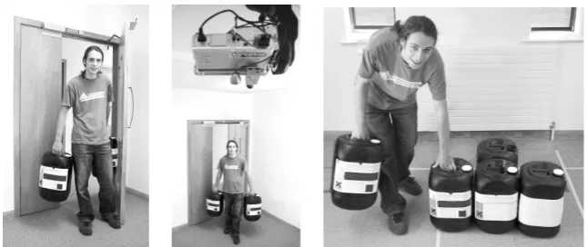
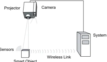
The main contribution of the cooperative augmentation approach is a flexible framework to allow smart objects to spontaneously use projection capability in an environment for output. Our approach can locate and track mobile objects in the environment, determine suitable areas for projection and finally align the projection with the object’s surfaces so it appears undistorted, as shown inFigure 1.
Smart Object
Projector Camera
System
Sensors
[image:3.595.210.399.158.268.2]Wireless Link
Fig. 1. Cooperative Augmentation of Smart Objects with Projector-Camera Systems
2 Related Work
The question of how to augment mobile objects with projected displays was investigated by Bandyopadhyay et al. in [1]. Objects with planar surfaces were equipped with a magnetic and infra-red tracking system. Static projectors were used to augment the objects in real-time. However, this work suffered from two key problems of latency and limited working volume due to the tracking systems used. Our approach uses a projector-camera system with a vision-based object detection system. This allows augmentation of objects anywhere within the field of view of the system at camera frame-rates, without relying on separate tracking hardware. The use of a camera also allows direct interaction with the projection, for example, by visual detection and tracking of the user’s fingertips as described by Kjeldsen et al. in [30].
Although there is an enormous body of work on detection and location of mobile non-smart objects using a camera, there is little work which uses the capabilities of smart objects themselves. For example, vision-based detection and tracking approaches have been taken by Ehnes et al. in [2], using AR Toolkit fiducial markers [3] to track and project on mobile planar surfaces. Borkowski et al. also demonstrate a mobile projected interactive display screen object tracked by its black border in [4]. However, both these systems rely on modifying or engineering the external appearance of a non-smart object to enable detection. In contrast, our approach uses features of the natural appearance of a smart object for detection.
sensors to guarantee correct pose calculation. For example, cubical objects require at least 3 sensors per face (18 total) to detect all poses.
In contrast, our cooperative augmentation approach does not require a minimum number of light sensors to operate. Instead, we use appearance knowledge stored in the object to visually detect the object with algorithms that offer robustness to partial occlusion. Movement sensor information is used to further constrain the detection task and distinguish between objects with similar appearances.
There exist many implementations of projector-camera systems – for example, we can decompose existing systems into three categories with respect to display mobility:
1. Static projector-camera systems
2. Steerable projection from static system with pan and tilt hardware 3. Mobile, handheld and wearable projector-camera systems
All types of projector-camera system have been used for augmenting objects with projection, however, static [1], mobile, handheld [7] or wearable [15] projector-camera systems can only opportunistically detect and project on objects passing through the field of view of the projector and camera.
In contrast, projector-camera systems in the second category with computer controlled steerable mirrors or pan and tilt platforms [16][2][4][17] allow a much larger system field of view and the ability to track objects moving in the environment. Levas et al. first presented a framework for steerable projector-camera systems to project onto objects and surfaces in their Everywhere Display framework [8]. However, although supporting a distributed architecture, this framework was limited to creating displays on static surfaces in locations pre-calibrated by the user. Our cooperative augmentation approach enables spontaneous displays on the surfaces of mobile smart objects without user intervention or calibration.
3 Cooperative Augmentation
This section expands the concept behind cooperative augmentation by explaining the three areasof cooperative augmentation:
1. The Object Model representation of the smart object. 2. The projector-camera system.
3. The cooperative augmentation process.
3.1 Object Model
The Object Model is a description of the object and its capabilities, allowing the projection system to dynamically configure its detection and projection services for each object at runtime. We assume the Object Model knowledge is embedded within the object during manufacture.
This allows an object to be uniquely identified on the network as a source and recipient of event messages and data streams.
2. Appearance Knowledge
This knowledge describes the appearance of the smart object. The description is specific information extracted by computational methods from camera images of the object. For example, colour histograms, an image of the object itself, or locations of features detected on the object. 3. 3D Model
A 3D model of the object is required in VRML representation to allow the projector-camera system to compute the object’s pose.
4. Sensor Knowledge
The sensor model is a description of the data delivered by the object’s sensors. The data type is classified into three groups with regard to the originating sensor: movement sensor data, light sensor data and others. The data is further classified into streaming or event-based, depending on the way sensor data is output from the smart object. The model contains associated sensor resolutions, and sensor range information to allow the projector-camera system to interpret sensor events.
5. Location and Orientation of the Object
When an object enters an environment, it does not know its location and orientation. The projector-camera system provides this information on detection of the object to complete the Object Model.
3.2 Projector-Camera Systems
A projector-camera system consists of a co-located projector and camera. We assume they are mounted so the respective projection and viewing frustums overlap, allowing objects detected by the camera system to be projected on by the projector.
In this work we use an intelligent steerable projector-camera system, composed of a computer-controlled pan and tilt platform on which the projector and camera are mounted. This platform is ceiling mounted for a greater view of the environment and can rotate the projector-camera system hardware in two dimensions – horizontal (pan) and vertical (tilt) about the centre of projection.
The projector-camera system has six main capabilities:
1. To provide a service allowing smart objects to register for detection and projection.
2. To search an environment for smart objects by automatically rotating the pan and tilt platform.
4. To track detected objects by automatically rotating the pan and tilt platform to centre the detected object.
5. To project an image onto an object in an area specified by the smart object, or choose the area most visible to the projector. This image is geometry corrected so that the image appears to be attached to the object’s surface and is undistorted.
6. To further correct an image before projection for variations in an object’s surface colour and texture so that the image appears more visible.
3.3 Cooperative Augmentation Process
To illustrate the cooperative augmentation process in action, we can imagine a goods warehouse scenario, in which objects are stored for distribution. In this scenario the objects are augmented with computing, giving them knowledge of their contents and sensors allowing them to monitor themselves and the local environment to ensure integrity and to maintain the authenticity of the goods[20]. Such sensing allows them to detect rough handling based on sensed movement and automatically report their position and status wirelessly for goods tracking and inventory purposes.
We can decompose the cooperative augmentation of an object such as a chemical container into five steps:
1. Registration
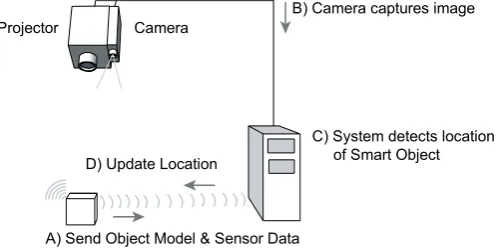
As the container enters the warehouse it detects the presence of a location and projection service through a service discovery mechanism. The object sends a message to the projector-camera system requesting registration for the projection service to display messages. On receipt of the registration request, the projector-camera system requests the Object Model from the smart object.
Projector
B) Camera captures image
C) System detects location of Smart Object
A) Send Object Model & Sensor Data D) Update Location
[image:6.595.180.432.495.620.2]Camera
Fig. 2. Detection Sequence Diagram
2. Detection
Object Model to constrain the visual detection process and generate location and orientation hypotheses (B and C). When an object is located with sufficient accuracy, the 3D location and orientation hypothesis is returned to the smart object (D). This process is explained in more detail in section 4.
3. Projection
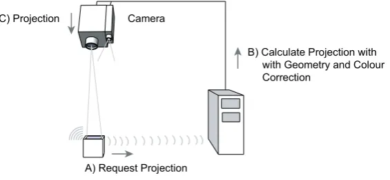
When an object has knowledge of its location and orientation it can request a projection onto its surfaces. For example, if it detects it has been dropped, it can request a message is projected onto it requesting employees visually inspect it for damage. This projection request message contains both the content to project and location description of where on the object to project the content, as shown in Figure 3 (A). The projector-camera system automatically corrects the projection of the message for the object’s geometry based on the 3D model stored in the Object Model and the calculated object location and orientation, so that it appears undistorted (B). The projection is also corrected for the surface colour of the object to make it more visible to the user [19]. The projector system starts displaying the corrected content on the objects surfaces immediately on receipt of the request, if the object is in view and the projector system is idle (C).
Camera
B) Calculate Projection with with Geometry and Colour Correction
[image:7.595.164.447.366.497.2]A) Request Projection C) Projection
Fig. 3. Projection Sequence Diagram
4. Manipulation of Smart Object
A requested projection is active as long as the object is detected, including during movement or manipulation of the object. Consequently, smart objects can give direct feedback to the user in response to the manipulation or movement of the object by changing their projection. For example, as the projector sends location information to the object, if an employee places an object in the wrong storage area of the warehouse it could request a warning message is projected until moved to the correct location.
5. Update Appearance
cooperative process this new knowledge can be re-embedded into the Object Model for faster and more robust detection on next entry to an augmented environment.
4 Visual Object Detection
The projector-camera system dynamically configures its visual object detection processing based on the type of appearance knowledge in the Object Model, and the sensors the object possesses.
Objects in the real world have appearances that vary widely, for example, in colour, texture, shape and the features that appear on their surfaces. Their appearance can also be easily changed by influences in the surrounding environment such as lighting conditions (including changes in intensity, colour and direction of lighting) or scene changes (such as partial occlusion by other objects or background changes). An object’s appearance also changes with the relative location and orientation of the object to the viewer.
To cope with these changes we use four different detection algorithms: i.) Colour Histograms
Swain and Ballard[27] first proposed the use of colour histograms to describe an object by its approximate colour distribution. Objects can be detected by matching a colour histogram from a camera image region to a histogram from a training sample of the object using histogram intersection and statistical divergence measurements such as chi-square (!2). Colour histograms offer a simple and fast object recognition method which has been shown to be robust to many transformations of an objects appearance, such as orientation, scale, partial occlusion and even shape. However, colour histograms are sensitive to changes in light intensity and colour.
ii.) Multidimensional Receptive Field Histograms
As many objects cannot be described by colour alone (for example, black objects), the histogram approach has been generalised by Schiele and Crowley [28] to multidimensional receptive field histograms. The histograms encode a statistical representation of the appearance of objects based on vectors of joint statistics of local neighbourhood operators such as image intensity gaussian derivatives (Dx,Dy) or gradient magnitude and the local response of the laplacian operator (Mag-Lap). Experimental results show the histograms are robust to partial occlusion of the object and are able to recognise multiple objects in cluttered scenes in real-time using the probabilistic local-appearance hashing approach proposed by Schiele and Crowley.
iii.) Shape Context
Context descriptor described by Belongie et al. in [29] to enable scale and rotation invariant matching of the contours.
iv.) Local Features
Local feature based detection algorithms aim to uniquely describe (and therefore detect) an object using just a few key points. To extract features, training images of an object are searched for a set of interest points (such as corners, blobs or lines) that can be repeatably detected under transformations of an objects appearance. The local image area immediately surrounding these interest points can then be used to calculate a feature vector which we assume serves to uniquely describe and identify that point. The feature descriptor can be a simple colour histogram of the local area, or as complex as the gaussian derivative histogram based SIFT algorithm, described by Lowe in [22]. Object detection now becomes a problem of matching a feature set between the training image and camera images. A comparison of different feature detection and descriptor algorithms can be found in[21].
The different detection methods are shown in Table 1, corresponding to different aspects of an objects possible appearance.
Appearance
Knowledge Detection Method
Discriminative Power
Cost in Time
Colour Colour histogram comparison Low Medium
Texture Multidimensional Receptive Field Histograms Medium Medium
Shape Contour detection and Shape Context Medium Medium
Local Features Interest point detection and feature descriptor comparison High High
Table 1. Appearance knowledge levels and detection methods with associated processing cost
These methods form a flexible layered detection process that allows an object to enter the environment with different levels of appearance knowledge. As we descend the table, the power of the detection methods to discriminate between objects with similar appearances increases, however, at the cost of increased processing time. We consider higher discriminative methods to hold more knowledge about the object.
Where an object holds more than one piece of appearance knowledge, one of two strategies can be followed. The first is using the most discriminative (least abstract) information to increase the probability of an accurate detection. The second strategy is to fuse the results of multiple detection methods to make the detection more robust. However, detection method selection is always a trade-off, as both the use of multiple methods and the more discriminative individual methods (such as local features) share the cost of increased processing requirements.
model of the background [14] to provide a basic figure-ground segmentation for the detection algorithms, increasing the probability of correct detection.
Maintaining a background model also allows us to take the object’s context into account when performing the method selection step, for example, we can compare the object’s colour histogram to the global environment colour histogram and if they are too similar we would not use the colour method as the probability of detection is low.
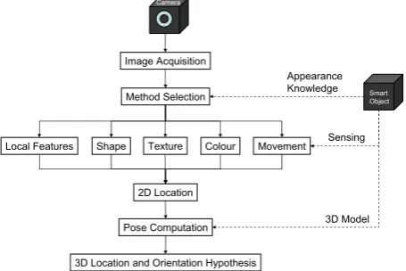
The detection method selection step forms part of the visual detection pipeline shown in Figure 4. Here, following each camera frame acquisition the method selection step is performed based directly on the appearance knowledge embedded in the object. If the object is successfully detected a 2D location result is generated. This can take the form of correspondences between extracted image features and features in the Object Model, or a 2D image region in which the object has been detected,
Image Acquisition
Local Features
Pose Computation
Smart Object
Appearance Knowledge
3D Model
Camera
Shape Colour Movement
2D Location
3D Location and Orientation Hypothesis Method Selection
[image:10.595.184.412.297.449.2]Sensing Texture
Fig. 4. Detection method selection based on smart object knowledge
Following 2D location of the object in the camera image, a pose computation step is performed. The object pose is calculated either directly from matched local feature correspondences or by fitting the 3D model to edges detected in the 2D image region from the detection step. RANSAC is used for robust model parameter estimation [26] and eliminates incorrectly matched correspondences. Typically the pose computation step achieves a mean location error under 5mm in the X and Y axes, 2cm in distance to object and mean orientation error under 1 degree with an object at 3m distance.
Sensing can also be used in the pose computation step if a smart object contains 3D accelerometer sensors. Here the sensed gravity vector can be directly used to constrain the number of 3D model poses that must be tested to match the edges detected in the 2D image region from the detection step.
5 Object Projection Processing
projector. The location description refers to the projection location abstractly or specifically. Abstract locations refer to faces of the object’s 3D model. For example, a projection can be requested on the top or front face. A more specific location can also be specified as coordinates in the 3D model coordinate system, allowing exact placement and sizing of the projection on an object.
There are cases where projection cannot begin immediately, such as where the system is busy, the object is occluded or the object is out of the field of view of the projector. Here the display requests are cached at the projector-camera system and the projection commences when the object is in view and the projector is available. Projection requests are displayed sequentially and can be ended by the object requesting a null content projection. Simultaneous projection onto multiple objects can be accomplished if all are detected within the field of view of the projector-camera system.
A rectangular image projected on to a non-perpendicular or non-planar surface exhibits geometric distortion. We compensate for this distortion by warping our projected image if we know both the surface geometry of the object and the orientation angle of the surface with respect to the projector. We obtain the orientation of the object from the object detection step, and the surface shape from the geometric 3D model contained within the Object Model. The surface shape directly configures the projection geometric correction method [18], as shown in Table 2.
Object Geometries Correction Method
Planar
Rectilinear Planar Homography Cylindrical
[image:11.595.181.419.388.456.2]Spherical Quadric Image Transfer Irregular Discretised Warping
Table 2. Projection geometric correction methods based on object geometries [18].
The projector-camera system uses a real-time colour correction algorithm developed by Fujii et al. [19] to correct for the colour of the object’s surface and make the projection more visible. This entails an initial one-time projection of four colour calibration image frames (red, green, blue and grey) to recover the reflectivity response of the surface followed by calculation of the adaptation algorithm for each frame to be projected.
6 Concept Validation
This section uses the scenario outlined in section 3 to present a concrete detection and projection process for two smart chemical containers in a warehouse.
6.1 Registration
the smart object to the projector-camera system. Here, an employee enters the environment with two smart chemical containers, as seen in Figure 5.
The projector-camera system registers the objects, and returns a confirmation message to the containers. On receipt of this message the containers begin sending sensor events to the projector-camera system. In this case, they are being carried by the employee so embedded accelerometer sensors generate movement events.
6.2 Detection
The registering objects trigger the detection process in the projector-camera system. Here the challenge is to simultaneously detect mobile or static objects and distinguish between objects with similar appearances.
[image:12.595.142.465.301.437.2]
Fig. 5. Left:New objects arrives in environment, Centre: An employee walks with containers, Right: The employee places one object on the floor
The steerable projector now rotates from its current position to search the environment. As the objects have just entered, the system does not know their location. Consequently, the projector system uses a creeping line search pattern with a horizontal major axis to thoroughly search the whole environment.
The projector uses the appearance knowledge embedded in the Object Model and the sensor events to configure its detection process. In this case the containers store knowledge of a colour histogram, and sense they are moving. This knowledge triggers the method selection step to choose colour and movement detection processes. The movement process generates a motion mask which is used by the colour detection process to constrain its search for the object by masking the back-projection result of the object’s colour histogram.
As the two chemical containers look identical, two possible objects are identified in the image. It is not currently possible for the camera to distinguish between the objects. Consequently the steerable projector tracks the moving areas in the camera image by centring their centre of gravity.
projector-camera system now only detects one moving area and the system can differentiate between the objects directly based on sensing. A 3D location and pose is now calculated and sent wirelessly to the containers, completing the Object Model.
6.3 Projection
Once an object’s 3D location and orientation is calculated by the projector-camera system, objects can request projection of content on their surfaces. Here the challenge is to correct the projection for the orientation of the object, and variations in its surface colour to ensure the most undistorted and visible projection.
[image:13.595.167.440.269.353.2]
Fig. 6. Left: Warning message projection on two chemical containers, Right: Scale and rotation invariant local features detected on chemical containers
The container detects it was put down in the wrong storage area based on the location it was sent and requests a warning message is projected (see figure 6). The projector-camera system projects the warning message on the front surface of the container objects so as to appear undistorted by drawing the text and images with the calculated transformations applied.
6.4 Manipulating the Object
When projecting onto objects, the object can respond to sensed manipulation or network events by dynamically modifying the projected content. The challenge here is to keep the projection aligned with the object as it is manipulated or moved.
The employee sees the projected message and picks up the object. The detection process continues to track it and generate 3D location and pose information. Consequently, the message appears to remain fixed to its surface as long as the surface is visible to the projector system. When the object is in the correct area it requests the projection stops. The employee puts down the container when they see the message disappear. The projector-camera system keeps tracking the objects.
6.5 Knowledge Updating
If objects enter the environment with only partial knowledge of their appearance, their knowledge can be increased over time by performing extra detection processes and re-embedding the result into the Object Model. The challenge is how to make the knowledge extraction accurate, given that the initial knowledge was incomplete.
features on the object just put down, as shown in Figure 8. The SIFT descriptors are calculated on small image patches around the detected interest points. The resulting 128 value feature vectors are mapped to locations on the object’s 3D model using the known 3D location and orientation of the container.
If the object is manipulated so it is rotated from its original pose new features will be detected as they come into view. The projector-camera system manages the Object Model local feature database to merge new features or update the database if the object appearance is changed. The new local feature appearance knowledge is sent to the smart containers to be embedded in the Object Model and used for faster, more accurate detection in future.
6.6 Objects Departing the Environment
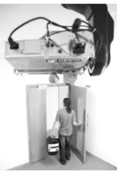
[image:14.595.261.345.375.498.2]When objects depart the proximity of the projector-camera system, their virtual object representation is removed by the projector system and the projector is free to track other objects. Here, the employee moves to the exit with the container that was never put down. This container continues to generate motion events. As there are no other moving objects or projections active, the projector system tracks the carried object, as shown in Figure 9.
Fig. 9. A container leaves the environment with the employee
As the employee exits through the door with the object, the system looses sight of the object and it no longer responds to messages from the projector-camera system. The system assumes it has departed the environment after a short time-out.
The projector-camera system then returns to the last-known position of the other container objects. If no objects can be detected the projector system begins an expanding square search pattern centred on their former locations.
7 Discussion
7.1 Registration
Currently, smart object registration and communication is performed over a wireless network, implemented using Smart-Its sensor nodes [23]. The wireless network bandwidth requirements for smart objects depend on where the sensor data is abstracted to events. If a sensor node is not powerful enough to perform this processing then raw sensor data must be streamed to another device on the network. Due to the 13ms timeslots used for each node with the Smart-Its AwareCon protocol [23], only a maximum of 2 smart devices can stream sensor data simultaneously and remain synchronised with a 30Hz (33.3ms) camera refresh rate.
The use of active smart objects with sensing provides three benefits over passive technologies such as RFID:
1. Active sensing (such as movement or light sensing) can constrain the detection process to make it more robust and differentiate between objects.
2. Objects whose appearance or geometry changes can update the projector-camera system dynamically with new appearance knowledge. (For example, if a user opens a smart book the appearance is updated and tracking is un-interrupted). 3. The object itself can be modelled as a state machine which requests projections
based on sensed changes in its environment, location or direct interaction with the projection. (For example, a message about how to assemble two smart objects can be projected only when they are moved together into the same location).
7.2 Detection
It has been reported by Brooks in [24] that users of projector based interactive systems routinely accept total system latencies of 150ms. There are three main sources of latency in the detection and projection framework – camera frame acquisition, image processing for object detection and projection. For a camera running at 30Hz the frame acquisition takes up to 33.3ms, while for a 60Hz projector a frame is projected every 16.7ms. Maximum latency before image processing is 50ms; consequently, the object detection step should be performed below 100ms.
The use of complex or multiple computer vision methods in the object detection step is CPU intensive. For example, a CPU optimised version of the SIFT local feature algorithm takes approximately 333ms to detect a single object in a 640x480 pixel image [22]. Our approach is to make use of the ability of the Graphics Processing Unit (GPU) on the graphics card to process pixels in parallel, allowing our system to achieve detection and augmentation of objects in near real-time.
7.3 Projection
Consequently, the use of colour correction techniques in the projection step was chosen, as it goes part way to solving these competing problems. Colour correction algorithms can change the projected image to correct for non-uniform and non-white surface colours. An image of the object without projection can also be calculated as part of this process and used for object detection.
Despite the large body of work on photometric correction, the algorithm by Fujii et al. [19] was chosen for this step as it is the only algorithm demonstrated to perform in real-time. However, this correction does have the cost of a one camera frame delay to allow the camera image to be used in the algorithm. The algorithm also cannot completely correct very saturated surfaces, as the dynamic range of typical projectors is not sufficient to invert the natural surface colour.
7.4 Manipulation of Objects
The maximum speed a smart object can move is limited by the camera frame rate and object detection step processing time. For an average camera acquisition and processing step of 133.3ms and a typical human walking speed of 5kph a handheld object could move 18cm. As the lack of projection would be very obvious to a user during a move of this distance, we can de-couple the projection from the detection step. By using a Condensation algorithm particle filter [25] to predict the 3D location and orientation of the smart objects between detections we can exploit the faster frame rate of the projector. The benefit of using a particle filter over a Kalman filter is that it allows us to model multiple alternative hypotheses; it can integrate detection results from multiple distributed cameras and better suits the non-linear movement typically seen in handheld objects.
7.5 Knowledge Updating
When the projector-camera system updates or merges new knowledge about an object, constraints on smart object sensor node memory limit the amount of knowledge that can be stored in a smart object. For example, the particle Smart-Its sensor node [23] currently only has 512KB of flash memory which can be used for Object Model storage. Our solution for larger models is to only store a URL link to the actual Object Model in the smart object (which assumes a network connection).
8 Conclusion
In this paper we have presented the concept of cooperative augmentation and validated our approach with an implementation using a warehouse scenario. We discussed issues arising from the implementation and the lessons learned.
The main challenges in our approach are real-time visual detection of smart objects, keeping the projection synchronised when the object is moved or manipulated and correcting the projection for non-ideal surface colours and textures.
More research is required in how different levels of knowledge change the detection performance, what impact sensing has on the robustness of detection and which computer vision algorithms are best suited to detecting the objects. Open questions remain in the area concerning location of projections on an object. Specifically, how can we determine the best strategy to ensure the most visible, readable and useable projection location on an object’s surfaces for the user? Also, if an object is in view of multiple distributed projector-camera systems, what is the best strategy to decide which system should project onto each object surface?
Acknowledgements
This research is supported by the EPSRC, the Ministry of Economic Affairs of the Netherlands through the BSIK project Smart Surroundings under contract no. 03060 and by Lancaster University through the e-Campus grant.
9 References
1. Dynamic Shader Lamps: Painting on Movable Objects, D. Bandyopadhyay, R. Raskar, H. Fuchs, In Proc. IEEE and ACM Int. Symposium on Augmented Reality, New York, 2001. 2. Projected Augmentation – Augmented Reality using Rotatable Video Projectors, J. Ehnes, K.
Hirota, M. Hirose, Third IEEE and ACM International Symposium on Mixed and Augmented Reality (ISMAR'04), September-October, 2004 Arlington, VA, USA.
3. Marker Tracking and HMD Calibration for a video-based Augmented Reality Conferencing System, Kato, H., Billinghurst, M. (1999), In Proceedings of the 2nd International Workshop on Augmented Reality (IWAR 99). October 1999, San Francisco, USA.
4. Projecting Rectified Images In an Augmented Environment, S. Borkowski, O. Riff, J. Crowley, IEEE International Workshop on Projector-Camera Systems (PROCAMS-2003), Nice, France, October 12, 2003.
5. Moveable Interactive Projected Displays Using Projector Based Tracking, J. C. Lee, S. E. Hudson, J. W. Summet, P. H. Dietz, Proceedings of the ACM Symposium on User Interface Software and Technology (UIST), pages 63-72, Seattle, WA. October 23-26, 2005.
6. Tracking Locations of Moving Hand-held Displays Using Projected Light, J. Summet and R. Sukthankar, In Proceedings of Pervasive 2005, Munich, Germany.
7. RFIG Lamps: Interacting with a Self-Describing World via Photosensing Wireless Tags and Projectors, R. Raskar, P. Beardsley, J. van Baar, Y. Wang, P.Dietz, J. Lee, D. Leigh, T. Willwatcher, In Proceedings of SIGGRAPH 2004, Los Angeles, USA.
8. An Architecture and Framework for Steerable Interface Systems, Levas, A., Pinhanez, C., Pingali, G., Kjeldsen, R., Podlaseck, M., Sukaviriya, N., in Proceedings of UbiComp 2003. 9. The MediaCup: Awareness Technology embedded in an Everyday Object, H. Gellersen, M.
Beigl, H. Krull, 1st International Symposium on Handheld and Ubiquitous Computing (HUC99), Karlsruhe, Germany, 1999. Lecture notes in computer science; Vol 1707, H-W Gellersen ed, ISBN 3-540-66550-1; Springer, 1999, pp 308-310.
10. Cooperative Artefacts: Assessing Real World Situations with Embedded Technology. M. Strohbach, H.-W. Gellersen, G. Kortuem and Christian Kray, In Proceedings of Ubicomp 2004, Nottingham, UK.
Holmquist (Eds). Lecture Notes in Computer Science, Vol 2498, Springer Verlag, Gothenburg, Sweden, September 2002, pp. 333 – 351.
12. Ubiquitous Interaction - Using Surfaces in Everyday Environments as Pointing Devices, A. Schmidt, M. Strohbach, K. Van Laerhoven, and H.W. Gellersen, 7th ERCIM Workshop "User Interfaces For All", 23 - 25 October, 2002.
13. Cooperative Artefacts: Assessing Real World Situations with Embedded Technology, M. Strohbach, H.-W. Gellersen, G. Kortuem and C. Kray, In Proceedings of: Ubicomp 2004. 14. Adaptive background mixture models for real-time tracking, C. Stauffer and W. E. L.
Grimson, In Computer Vision Pattern Recognition, pages 246--252, Ft. Collins, CO, 1999. 15. A Wearable Mixed Reality with On-board Projector, T. Karitsuka, K. Sato, In Second IEEE
and ACM International Symposium on Mixed and Augmented Reality (ISMAR2003), 7-10 October 2003, Tokyo, Japan.
16. The Everywhere Displays Projector: A Device to Create Ubiquitous Graphical Interfaces, C. Pinhanez, Proceedings of Ubiquitous Computing 2001 (Ubicomp'01), September 2001. 17. Searchlight: A Lightweight Search Function for Pervasive Environments, Andreas Butz,
Michael Schneider, and Mira Spassova, Pervasive Computing, Second International Conference, PERVASIVE 2004, Vienna, Austria, April 21-23, 2004.
18. Spatial Augmented Reality Merging Real and Virtual Worlds, O. Bimber and R. Raskar, A K Peters LTD (publisher), ISBN: 1-56881-230-2.
19. A Projector-Camera System with Real-Time Photometric Adaptation for Dynamic Environments, K. Fujii, M.D. Grossberg and S.K. Nayar, IEEE Conference on Computer Vision and Pattern Recognition (CVPR), Vol.1, pp.814-821, Jun, 2005.
20.eSeal – a system for enhanced electronic assertion of authenticity and integrity. C. Decker, M. Beigle, A. Krohn, P. Robinson, U. Kubach, In Pervasive 2004 (2004) Vienna, Austria. 21. Scale and Affine invariant interest point detectors, K. Mikolajczyk and C. Schmid, In
Proceedings of IJCV 60(1):63-86, 2004.
22. SIFT: Distinctive image features from scale invariant keypoints, D. Lowe, In Proceedings of IJCV 60(2):91-110, 2004
23. The Particle Computer System, IPSN Track on Sensor Platform, Tools and Design Methods for Networked Embedded Systems (SPOTS), Christian Decker, Albert Krohn, Michael Beigl, Tobias Zimmer, In Proceedings of the ACM/IEEE 4th International Conference on Information Processing in Sensor Networks (IPSN05), pp443-448, Los Angeles, April 2005. 24. What’s Real About Virtual Reality?, F.P. Brooks, Jr., IEEE Computer Graphics and
Applications, 19, 6: 16-27, 1999.
25. CONDENSATION -- conditional density propagation for visual tracking, Michael Isard and Andrew Blake, In International Journal of Computer Vision, 29, 1, 5--28, 1998. 26. Random sample consensus: a paradigm for model fittingwith applications to image analysis
and automated cartography, M.A. Fischler, and R.C. Bolles, Communications of the ACM 24, 6 (Jun. 1981), 381-395.
27. Color indexing. M. J. Swain, and D. H. Ballard, International Journal of Computer Vision, 7(1). 1991.
28. Recognition without Correspondence using Multidimensional Receptive Field Histograms, International Journal of Computer Vision, 36(1), pp.31-50, 2000.
29. Matching Shapes, S. Belongie, J. Malik, J. Puzicha, In International Conference on Computer Vision (ICCV'01), 2001.
![Table 2. Projection geometric correction methods based on object geometries [18].](https://thumb-us.123doks.com/thumbv2/123dok_us/7981647.756885/11.595.181.419.388.456/table-projection-geometric-correction-methods-based-object-geometries.webp)