A Novel Algorithm for MPPT for PV Application System
by use of Direct Control Method
D. D. Gaikwad
KIT’s College of Engineering Kolhapur
Maharshtra, India
M. S. Chavan
KIT’s College of Engineering Kolhapur
Maharshtra, India
ABSTRACT
Photovoltaic (PV) cell converts sunrays into electrical energy, which has non-linear I-V characteristics. For extracting maximum power from photovoltaic (PV) array for varying environmental conditions, it is necessary to use MPPT tracker. The MPPT consists of DC-DC converter and MPPT algorithm, DC-DC converter is inserted between solar panel and load or battery. The task of MPPT tracker is to match input impedance of the converter and it is equals to the equivalent output impedance of the solar panel to achieve unique point (MPP) where maximum power extracted. The used TL598 based DC-DC converter operates with defined MPPT algorithm. The DC-DC converter output power is controlled by varying its duty cycle to operating at knee voltage level. The novel algorithm is used for efficiently extracts the maximum output power from PV panel with the use of direct control method. The sensing of input voltage and current parameters, which are processed based on P&O algorithm. After finding of MPP, it latched and stops searching and only continuously monitors source voltage. When any change in environmental conditions, the MPPT algorithm again starts searching MPP unique point which is totally based on source voltage information. This approach gets a stable output power at MPP. The algorithm has developed for direct control of duty cycle for DC-DC converter based on TL598. This is simple structure; obtain higher efficiency and reliability as compared to standard methods. The MPPT has capability to propose the technique which has been verified experimentally with a 75-W solar panel for different insolation (incident solar radiation) level and under large signal insolation of level changes.
General Terms
PV Cell Operating point, Algorithm.
Keywords
MPPT methods, Basic Theory, Methods of control technique, Algorithm.
1.
INTRODUCTION
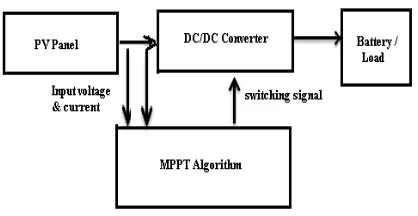
Now a day’s need of renewable sources of energy is important due to huge consumption and exhaustion of fossil fuel. Among available renewable energy sources, Photovoltaic panel due to pollution free, little maintenance and it is noise free. PV array are used in many applications such as water pumping, battery charging, hybrid vehicles, and grid connected PV systems. Power delivered from a PV panel depends on present environment conditions (irradiation and temperature), therefore PV needs the operating point to be tracked continuously in order to optimize the maximum available power (MPP) from using a Maximum Power Point Tracker (MPPT) algorithm [1]-[3]. MPPTs utilize a DC-DC converter to extract energy from solar cells and deliver it to
[image:1.595.326.535.243.351.2]the load. The general block diagram of a MPPT shown in Fig. 1
Fig 1: Block diagram of a MPPT
1.1
MPPT Methods
Large number of MPPT methods and different DC-DC converter topologies have been proposed for extracting the power from solar energy are presented and find the maximum operating power point (MPP). These various methods are available in terms of cost, speed, required sensors, implementation, complexity, popularity, and some other conditions [2].
However, number of researchers finds various techniques; they are categorized in order to conventional techniques and artificial intelligence techniques [4]. The most conventional useful techniques are Fractional and [5], Hill Climbing (HC) [5][6], Perturb and Observe (P&O) [4], Incremental Conductance (IncCond) [2],[8], and the most usable artificial intelligent techniques are Fuzzy Logic [9][10] and Neural Network [11] methodologies. Table I, compares these different methods by focusing on specific criteria.
1.2
Basic Theory
If solar panel is directly connected to the battery load or Resistive load, the characteristics of voltage and current curve resultant of PV panel is determine by the actual load on it. That is, load impedance forcefully moves the operating point of PV panel to locate the junction I-V and load line curve. Hence, this operating point generally is away from maximum power point taken out. Because of PV power change due to environmental changes, hence there is no such guarantee to deliver maximum power. By use of MPPT controller leads to resolve the mismatching impedance between connected load and PV panel.
match loads impedance to the optimal impedance of PV panel due to which the operating point of PV module is kept at the MPP. Fig. 2 illustrates the basic concept of load matching. For the input impedance of Buck-Boost DC-DC converter, which is between input impedance of converter (Rin) and load’s impedance (Rload), the mathematical equation 1 shows. By use of this Rin impedance, we can adjust by changing the duty cycle by use of defined algorithm to be matching with the optimal value or operating point. Thus this optimal impedance is where the MPP is located in I-V curve so its value is equal to Vmpp ⁄ Impp[12].
Table 1: Comparison of MPPT methods [12]
MPPT Techniques
Speed Complexity Reliability
Fractional Isc Medium Medium Low Fractional
Voc
Medium Low Low
IncCond Varies Medium Medium P & O Varies Low Medium
Fuzzy Logic Fast High Medium
Fig 2: MPPT role for load matching [12]
Derived equation for load matching [12]
Rin = (1)
Ropt = (2)
Rin = Ropt (3)
= (4)
2.
RESEARCH PROBLEM
Normally PV has nonlinear I-V Characteristics it changes with environment change [1]. A unique point where maximum output power takes place called MPP.
Various techniques uses in photovoltaic (PV) systems to maximize the PV array output power continuously due to change on load, panel temperature, and irradiance conditions. The Perturb and observe (P&O) MPPT algorithm is the most commonly used method because of its ease of implementation. However, it has some drawback such as the oscillation of the operating point around the MPP at steady state, which consumes a portion of the available energy. In
addition, the P&O algorithm may confused by rapidly changing atmospheric conditions that can lead into unstable system [2].
Incremental conductance, on the other hand, requires differentiation, division circuitry and a relatively complex decision making process and therefore requires a more complex microcontroller with more memory [2].
By observing the various algorithms, it found that each has some limitations on extracting power from Photovoltaic cells. In this paper, we proposed a Novel algorithm for MPPT Charger, it is possible to obtain stable output at MPP point that tracks every time changes in environment and improves speed, accuracy, and efficiency of PV array. The developed Novel algorithm for MPPT Charge controller for PV application is based on measure of voltage & current calculates existing power and increase / decrease duty cycle to obtain peak point then tracks according to source voltage reference for achieving all the time maximum power from PV. Less number of sensors needed in the controller circuitry since the MPPT controller is only utilizing the source voltage information. By utilizing a variable step-size algorithm, it improves the speed, accuracy, and efficiency of the PV system for better MPP.
3.
MATERIAL AND METHODS
Number of researcher’s fined various algorithm and controlling methods for MPPT tracking. Various algorithm uses control methods are PI control, direct control, and output voltage sensing method. All these methods include tracking algorithms to improve either by tracking speed or steady state oscillations. The most useful control method for MPPT is reference voltage adjustment. The block diagram of common method is as shown in Figure 3. It shows that, The MPPT algorithm adjusts reference voltage with sense of input voltage and current. By comparing this reference voltage and actual voltage, it generates error signal. This error signal compensated by PI controller and then PWM signal will energize the gate drive. [12]
[image:2.595.328.528.578.742.2]The other control method is duty cycle adjustment. This control method is also known as direct control method, as shown in Fig. 4 [12]. This control method is simpler and uses only one control loop, and it performs the directly adjustment of duty cycle of DC-DC converter within the MPP tracking algorithm. The adjustment of duty cycle is totally based on which algorithm is preferred. Due use of this PI loop has been removed.
Fig. 4 Block diagram for duty cycle adjustment [12]
4.
PROPOSED TECHNIQUE
To address this issue, a Novel control system and tracking algorithm based on input voltage sensing control algorithm. The main difference of proposed control system with existing ones is, after finding the peak unique point PWM signal latch that peak point and monitor source voltage for change of input voltage due to change in environmental condition. Accordingly takes the decision-making action against increasing or decreasing of duty cycle of DC-DC converter. However, problem on wastage of energy due to steady state oscillation at MPP is totally solves. The TL598 based DC-DC Converter is a PWM control 16 pin IC, it has two high gain error amplifiers. One amplifier used for maintain constant output voltage another for output current for protection against over current. This converter has dead time control Pin (DTCON) that can directly control duty cycle.[13] When we apply adjustable DAC output voltage to this pin get directly control of duty cycle. The block diagram of proposed control system and flowchart of tracking algorithm is illustrated in Fig. 5 and Fig. 6 respectively.
[image:3.595.58.260.72.265.2]During normal operation, the algorithm tracks with the sensing of input voltage and current by calculating existing and previous power according to adjustments of duty cycle through direct control of TL598 based DC-DC converter. For more clarification for MPPT algorithm for various condition of PV output power track rapidly and low stable oscillation at Knee point as shown in Fig. 7.a,b and Fig. 8 respectively.
Fig. 5 Block diagram for proposed control method
Table II. Electrical parameter of EOC75 module
Maximum Power (Pmp) 75Wp- 0/+3%
Open circuit voltage (Voc) 22.21V Short circuit current (Isc) 4.25A Voltage at maximum power (Vmp) 18.50V Current at maximum power (Imp) 4.06A
[image:3.595.309.553.81.510.2]Normal operating temperature 44.60C Temperature coefficient -1.036W/oC
Fig.6. Flowchart for proposed tracking algorithm
5.
RESULTS
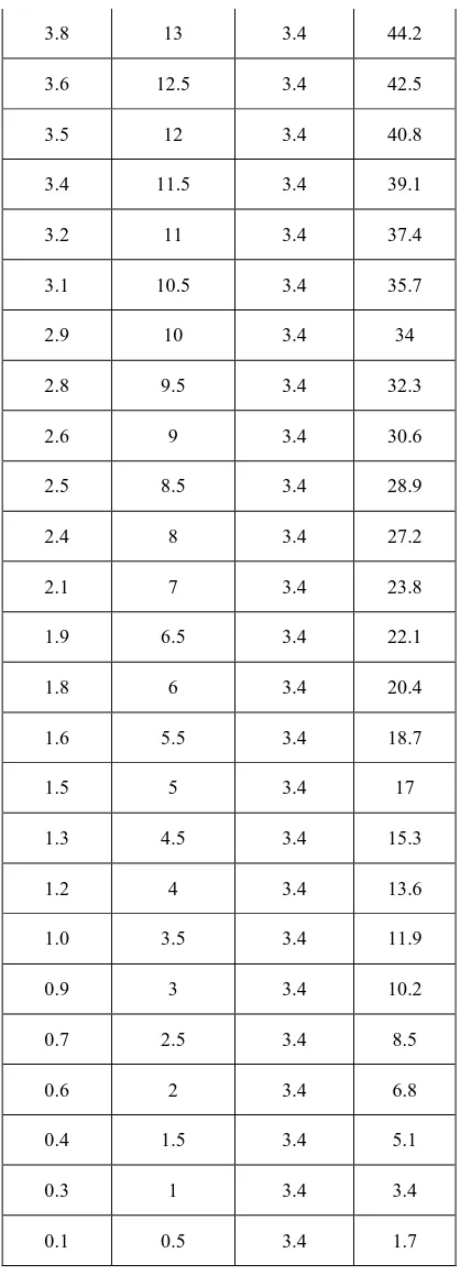
[image:3.595.58.279.581.747.2]The actual maximum power extracted (PMAX) from PV, there are three methods to be used for verifying the performance of proposed algorithm. The first method is use of variable resistive. Second is DC-DC converter which operate as constant voltage regulator for 10 ohm load and third method is a proposed MPPT controller, all these plotted together shown in Fig.7.a. The PV delivers maximum current of 3.4 Amp while short circuit of PV panel, which is corresponding to that time irradiance and temperature. For the first method, we decrease the variable load resistance connected across PV, the output current goes on increasing minimum to maximum. According to the results, computed PMAX is 47W, and when we use with second method it extract 26.5W. Whereas, the use of proposed algorithm it extract 46.5W. Therefore, the tracking efficiency is 98 %. The detail of the tracking performance is presented in Fig.7.a, while the steady state performance of the tracker as shown in Fig. 7.b.
[image:4.595.57.265.270.417.2]Fig. 7.a comparison of with and without MPPT controller extracted output power
Fig. 7.b. Tracked maximum power and Extracted PV power (Steady state Performance)
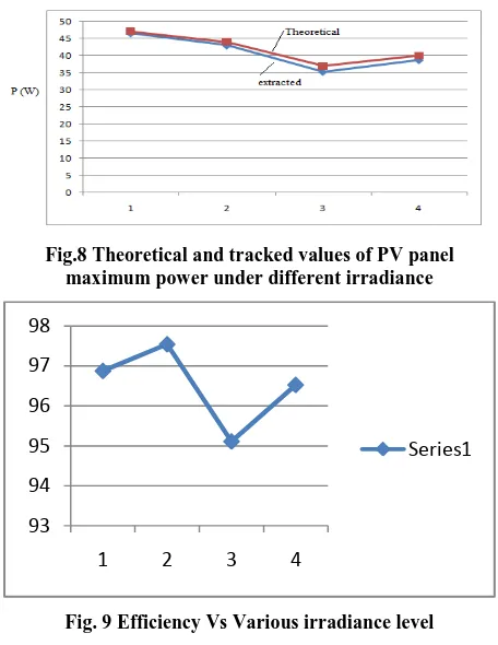
Fig. 7.b. illustrates the steady state performance of the MPPT for same operating condition. It is clear that the PMAX does not oscillate. The actual extracted PV power is 47W. Table III shows that output delivered power from PV for various load condition on 2/11/2014 at 11.45 AM for 75W PV panel. To evaluate the performance of the proposed algorithm, a comparison between actual delivered power from PV and computed power from proposed algorithm, which are carry out for different values of solar irradiance and the results are plotted in Fig. 8. Moreover, the corresponding tracking efficiencies of the proposed MPPT under different irradiance levels are computing and presented as shown in Fig. 9. According to the obtained results, the tracking efficiency is not less than 95%. Therefore, the proposed method guarantees that good tracking efficiency under different operating conditions.
Fig.8 Theoretical and tracked values of PV panel maximum power under different irradiance
Fig. 9 Efficiency Vs Various irradiance level
Table : III power delivered from PV to load by use of variable resistive load across PV panel.
Resistance in Ohm
Voltage across load
in Volts
Current through load in Amps
Delivered Power from PV
open 20 0 0
39.0 19.5 0.5 9.75
31.7 19 0.6 11.4
23.1 18.5 0.8 14.8
18.0 18 1 18
13.5 17.5 1.3 22.75
10.0 17 1.7 28.9
8.7 16.5 1.9 31.35
7.3 16 2.2 35.2
6.2 15.5 2.5 38.75
5.6 15 2.7 40.5
4.3 14.24 3.3 47
4.2 14 3.3 46.2
3.9 13.5 3.4 45.9
93 94 95 96 97 98
1 2 3 4
[image:4.595.58.267.437.540.2]3.8 13 3.4 44.2
3.6 12.5 3.4 42.5
3.5 12 3.4 40.8
3.4 11.5 3.4 39.1
3.2 11 3.4 37.4
3.1 10.5 3.4 35.7
2.9 10 3.4 34
2.8 9.5 3.4 32.3
2.6 9 3.4 30.6
2.5 8.5 3.4 28.9
2.4 8 3.4 27.2
2.1 7 3.4 23.8
1.9 6.5 3.4 22.1
1.8 6 3.4 20.4
1.6 5.5 3.4 18.7
1.5 5 3.4 17
1.3 4.5 3.4 15.3
1.2 4 3.4 13.6
1.0 3.5 3.4 11.9
0.9 3 3.4 10.2
0.7 2.5 3.4 8.5
0.6 2 3.4 6.8
0.4 1.5 3.4 5.1
0.3 1 3.4 3.4
0.1 0.5 3.4 1.7
[image:5.595.60.269.68.647.2]Table III shows that actual maximum power delivered when load impedance match with PV panel impedance. The readings are taken by varying the resistive load and monitors extracted power and operating PV panel voltage. This is 47W at the time of test conducted. In addition, same panel connected to a DC-DC regulator, which extract 26.25W, whereas, same panel connected to a proposed MPPT circuit, it extract 46.5 W as shown in table IV.
Table: IV shows extracted output power from PV for DC-DC regulator and proposed MPPT.
Panel operating voltage in Volts
Current flow through PV
in Amp
Extracted power from PV panel in
Watts
Used Method
7.5 3.5 26.25 DC-DC
regulator
15 3.1 46.5 Proposed
MPPT
6.
CONCLUSION
This paper presents a source voltage information based MPPT controller. By use of Novel algorithm technique the proposed MPPT algorithm adopts it perturbation and observe power with increase or decrease duty cycle of DC-DC Converter for achieving peak power. Where, duty cycle of DC-DC converter is latched. At the same time it achieve a stable output power and monitors only source voltage information for sensing any change in environment for operation of obtaining maximum power all the times. For validate the performance of proposed MPPT controller. The experimental results show that the proposed MPPT algorithm is accurate and simple method. It has fast dynamic response and high efficiency under various environmental conditions. Also it does not oscillate at peak point. However, the proposed method attempts to extract maximum power from the PV by use of DC-DC converter with direct control method.
7.
ACKNOWLEDGMENTS
The authors would like to thank the authorities of KIT College of Engineering, Kolhapur for providing facilities to carry out the research work.
8.
REFERENCES
[1] W. Xiao, J. Lind, W. Dunford, and A Capel, “Real-Time Identification of Optimal Operating Points in Photovoltaic Power Systems”, IEEE Transactions on Industrial Electronics, vol.. 53, no. 4, August 2006. [2] T. Esram, P.L.Chapman, Comparison of Photovoltaic
Array Maximum Power Point Tracking Techniques IEEE Transactions on Energy Conversion, vol.. 22, no. 2, June 2007.
[3] J. Park, J. Ahn, B. Cho, and G. Yu, Dual-Module-Based Maximum Power Point Tracking Control of Photovoltaic Systems, Transactions on Industrial Electronics, vol.. 53, no. 4, August 2006.
[4] N. Khaehintung, T. Wiangtong, and P. Sirisuk, "FPGA implementation of MPPT using variable step-size P&O algorithm for PV applications," 2006, pp. 212-215. [5] M. A. S. Masoum, H. Dehbonei, and E. F. Fuchs,
"Theoretical and experimental analyses of photovoltaic systems with voltage and current based maximum power-point tracking," Energy conversion, IEEE transactions on, vol. 17, pp. 514-522, 2002.
[image:5.595.312.543.78.239.2][7] W. Xiao and W. G. Dunford, "A modified adaptive hill climbing MPPT method for photovoltaic power systems," 2004, pp. 1957-1963 Vol. 3.
[8] Henry Shu-Hung Chung, K. K. Tse, S. Y. Ron Hui, Fellow,C. M. Mok, and M. T. Ho, " A Novel Maximum Power Point Tracking Technique for Solar Panels Using a SEPIC or Cuk Converter," IEEE Transaction on power electronics, VOL. 18, NO. 3, may 2003.
[9] N. Khaehintung, K. Pramotung, B. Tuvirat, and P. Sirisuk, "RISC microcontroller built-in fuzzy logic controller of maximum power point tracking for solar-powered light-flasher applications," 2004, pp. 2673- 2678 Vol. 3.
[10] M. Veerachary, T. Senjyu, and K. Uezato, "Neural-network-based maximum-power-point tracking of
coupled - inductor inter leaved-boost converter- supplied PV system using fuzzy controller," Industrial Electronics, IEEE Transactions on, vol. 50, pp. 749-758, 2003. [11] T. Hiyama, S. Kouzuma, and T. Imakubo,
"Identification of optimal operating point of PV modules using neural network for real time maximum power tracking control," Energy conversion, IEEE transactions on, vol. 10, pp. 360-367, 1995.
[12] Mehdi Hassani, Saad Mekhilef, Aiguo Patrick Hu, Neville R. Watson,” A Novel MPPT Algorithm for Load Protection Based on Output Sensing Control,” IEEE PEDS 2011, Singapore, 5 - 8 December 2011.
![Fig. 3 Block diagram for Vref adjustment [12]](https://thumb-us.123doks.com/thumbv2/123dok_us/8025267.767223/2.595.328.528.578.742/fig-block-diagram-vref-adjustment.webp)