Image Fusion Technique using DWT & PCA
Techniques
Prof. RupaliS. Gadekar, Prof. N. A. Gore2
1
E & TC Department, University of Pune, INDIA
2
Electrical Engineering Department, Bhivarabai Sawant COE, Narhe, Pune-411046, Maharastra, INDIA.
Abstract: Image fusion is basically a process where multiple images are combined to form a single resultant fused image. In this paper, Wavelet based Image fusion algorithm and Principal Component Analysis algorithm are designed with the help of Matlab/ Simulink and their comparative analysis is done with the help of parameter evaluation for various test images. Image processing algorithms conventionally implemented in DSP, ARM processors are limited by throughput which becomes very critical parameter for several image processing applications.
Keywords: Image fusion, DWT, PCA, Matlab/ Simulink,
I. INTRODUCTION
Image fusion is an important research topic in many related areas such as computer vision, automatic object detection, remote sensing, image processing, robotics, and medical imaging. Image fusion is a technique that deals with creating an image where all the objects are in focus. Image fusion is a process which combines the data from two or more source images from the same scene to generate one single image containing more precise details of the scene than any of the source images. It is the processing of images about a given region obtained from different sensors by a specific algorithm. The fused data provides more complete information than the separate dataset. The composite image is formed to improve the image content and to make it easier for the user to detect, recognize and identify targets.
II. LITERATURESURVEY
A. Image Fusion Methods
The image fusion methods are classified according to the data entering the fusion and according to the fusion purpose. [17]
1) Multimodal fusion: Images of different modalities are taken like PET, CT, MRI, visible, infrared, ultraviolet, etc. The goal is to decrease the amount of data and to increase the band-specific information.
2) Multi-temporal fusion: Images taken at different times in order to detect changes between them.
3) Multi-focus fusion: Images of a 3D scene taken repeatedly with various focal lengths. The technique used here is to identify the regions in focus and combine them together.
4) The multi-sensor fusion: It is used to achieve high spatial and spectral resolutions by combining images from two sensors, one of which has high spatial resolution and the other one has high spectral resolution.
5) Multi-view fusion: Images of the same modality are taken but at the same time taken from different places or different operating conditions. [17]
B. Image Fusion Algorithms
The different fusion algorithms are described below:
1) Morphological pyramid: In this method, two levels of filtering are performed on the input image matrices namely image opening and image closing. Image opening is a combination of image erosion followed by image dilation. Image closing is the inverse process of image opening. A combination of image opening and image closing removes the noise in the image. [11]
2) The Gaussian pyramid: This method contains a sequence of images in which each member of the sequence is a low pass filtered version of its predecessor. [10].
3) Ratio of Low Pass Pyramid: In this method, at every level the image is the ratio of two successive levels of the Gaussian pyramid. [8]
5) Discrete Wavelet Transform: In this method of fusion, once the image is decomposed with the help of wavelet transform, a composite multi-scale representation is built by a selection of the wavelet coefficients and choosing the maximum of the absolute values.
II. SOFTWAREDESIGN
In this paper, Image fusion is described using Wavelet based technique called as Discrete Wavelet Transform and Principal Component Analysis on multi-focus images. Image fusion is basically a process which combines the data from two or more source images from the same scene to generate one single image containing more precise details of the scene. [1]
A. Software Design
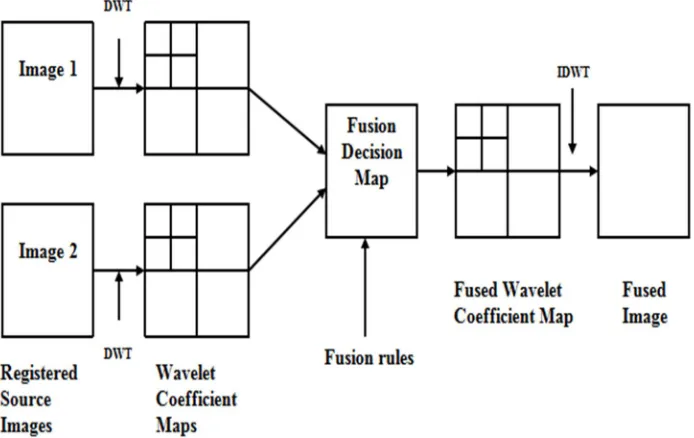
[image:3.612.133.480.265.484.2]1) Modelling of Greyscale Image fusion using DWT algorithm: The Fig. 2 shows the block diagram of DWT-IDWT based image fusion process which consists of two registered source input images, Wavelet coefficient map, Fusion Decision Map, and the fusion block. The two input images image1 and image 2 that are captured from camera are taken as inputs. The wavelet transform decomposes the image into low-low, low-high, high-low, high-high frequency bands.
Fig. 2 DWT-IDWT based image fusion
The wavelet coefficients are generated by applying the discrete wavelet transform technique on input images. Wavelet coefficients of the input images are fused by taking the average of input images. The resultant fused image is obtained by applying the inverse wavelet transform IDWT at the receiver. A software model for both the algorithms is prepared in Matlab with the help of Simulink. Fig.3 shows the modelling of Greyscale Image fusion using DWT algorithm. By double-clicking on the Simulink icon in Matlab, the Simulink Library Browser opens. The Video and Image Processing toolbox from the Simulink library is used to design this model. From this toolbox, we access the different elements used to design this model. The various blocks, elements and the sub-systems included in this model are described in detail below. Fig.3 shows the Simulink design model of image fusion for gray scale images of size 256×256 along with performance evaluation using DWT algorithm. The function of each block used to design model is described below.
B. Image from File block
This block is basically used to access the two input images which are to be fused. Two input images of size 256 × 256 are taken as input images. Each time to run the model for different dataset; we have to give the path of input images.
C. Video Viewer Block
Fig. 3 Modelling of Greyscale Image fusion using DWT algorithm
D. Embedded Matlab function Block for Image Fusion
This block is also called as S-function block, where we actually embed the code for the designed algorithm. This block is programmed using Discrete Wavelet Transform and Inverse Wavelet Transform algorithm for fusion of the two input images and the software model is prepared. The fused image is then displayed with the help of Video Viewer block.
E. PSNR and RMSE of Input mage 1 and Fused Image
An embedded function block is used to calculate the PSNR and RMSE of the fused image with reference to the input image1. The code for calculating PSNR & RMSE is scripted in the embedded function block.
F. PSNR and RMSE of input Image 2 And Fused image
An embedded function block is used to calculate the PSNR and RMSE of the fused image with reference to the input image2. The code for calculating PSNR & RMSE is scripted in the embedded function block.
G. Standard Deviation
This block is accessed from parameter block set. It is used to calculate the contrast between the fused and the input images.
H. Entropy
It quantifies the information content preset in the fused image. This model is tested for gray scale plane. jpg and clock. jpg images of size 256×256 and the performance metrics are calculated and tabulated in Table 5.1
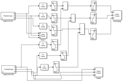
Fig. 4 Modelling of RGB Image fusion using DWT algorithm
IDWT is then applied on the fused wavelets to obtain the resultant fused image. This model is tested for various set of color images and the fused image is stored in workspace for further performance parameter analysis.
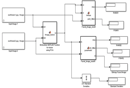
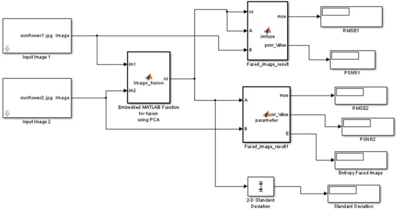
[image:5.612.193.409.497.643.2]2) Modelling of Image fusion using PCA algorithm: PCA is performing the fusion as a weighted superposition of all the input images. The optimal weighting coefficients, with respect to information content and redundancy removal, can be determined by a principal component analysis (PCA) of all input intensities. By performing a PCA of the covariance matrix of input intensities, the weightings for each input image are obtained from the eigenvector corresponding to the largest eigenvalue. Fig. 5 shows the image fusion based on PCA Analysis.
Fig. 5 PCA based image fusion
Fig. 6 Modelling of Image fusion using PCA algorithm
III.RESULTSANDCOMPARATIVEANALYSIS
A. Parameter Evaluation of the Greyscale Fused Images
Different performance evaluation metrics like Peak Signal to Noise Ratio (PSNR), Root Mean Square Error (RMSE), Standard Deviation (SD) and Entropy are calculated for the plane. jpg and clock. jpg fused images using both techniques DWT and PCA in Simulink. The fused image is obtained in Matlab by selecting the respective input images each time and running the Simulink model. Fig.7 shows the input test images to be fused and Fig.8 shows the different fusion results obtained by running the Simulink model with the help of DWT and PCA techniques. The top and bottom focused images plane. jpg of size 256×256 are taken as input images for fusion.
a) Bottom Focused image file plane.jpg b) Top focused image file plane. jpg Fig.7 Top & bottom Focused Input images
Performance evaluation measures of the various greyscale fused images of size 256×256 using PCA
Input test Images to be
fused PSN R 1 PSN R 2 RMSE 1 RMSE 2
SD Entropy
Clock. jpg 76.79 76.77 0.001 38
0.001 37
0.10 0.95
Plane. jpg 76.28 76.32 0.001 54
0.001 53
[image:7.612.210.401.519.706.2]0.13 0.4963
Table 4.2: Performance measures of greyscale fused images using PCA
A comparative analysis between both the algorithms show that the results achieved using PCA technique are much better as compared to PCA. The PSNR values of the input images with respect to fused images are higher in case of PCA, thus proving increased quality image. Also the RMSE values of the input images with respect to fused images are lower in case of PCA as compared to DWT proving less noise in PCA. PCA shows higher values of PSNR as compared to DWT and much lower values of RMSE, thus proving more efficient. Also when the size of image is increased, the PSNR values are higher and the RMSE values are lower. This shows increased performance of both the algorithms. However, PCA shows much better results in comparisons to DWT. Color test input images of size 256×256 like sunflower. jpg, ball. jpg, peaches. jpg, balloon. jpg and beaches. jpg images are taken as test input images for fusion.
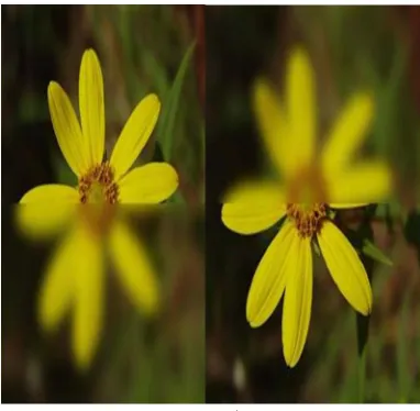
a) Top focused image flower. Jpg b) Bottom focused image flower. jpg Fig. 11 Top & Bottom focus Input images
Performance evaluation measures of the various greyscale fused images of size 256×256 using DWT
Input test Images to be fused PSN R 1 PSN R 2 RMSE 1 RMSE 2
SD Entrop
y
Clock. jpg 74.64 77.39 0.0022
5 0.0011 9 0.18 3 0.9506
Plane. jpg 75.21 75.63 0.0019
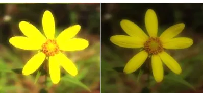
a) Fused flower. jpg image using DWT b) Fused flower. jpg image using PCA Fig. 12 Fused images of flower. Jpg
Table 4.3: Performance measures of RGB images using DWT
Performance evaluation measures of the various RGB fused images of size 256×256 using DWT
Input test Images to be fused PSN R 1 PSN R 2 RMSE 1 RMSE 2
SD Entropy
Flower.jpg 61.09 61.08 0.0509 8
0.0511 2
0.37 0.926
Ball.jpg 58.35 58.44 0.0957 8
0.0938 7
[image:8.612.143.471.349.543.2]0.27 0.7822
Table 4.4 Performance measures of RGB fused images using PCA
Performance evaluation measures of the various RGB fused images of size 256×256 using PCA
Input test Images to be
fused PSN R 1 PSNR 2 RMSE 1 RMSE 2
SD Entropy
Flower.jpg 76.76 76.2 0.00138 0.0039 5
0.21 0.6316
Ball.jpg 75.89 75.78 0.00168 0.0017 3
0.29 0.984
IV. CONCLUSION
The result of image fusion is a new image that retains the most desirable information and characteristics of each input image. The fused image contains greater information content for the scene than any one of the individual image sources alone. The composite image is formed to improve the image content and to make it easier for the user to detect, recognize and identify targets. The resultant image is more reliable, clear and more accurate. The fusion results of both DWT and PCA algorithms shows better results in terms of quality, information and noise in the input images. The future scope of the system will be to implement the fusion strategy for more than two images so as to achieve a fused image of better quality having high PSNR. To implement strategies to increase the PSNR of the fused image to a very high level so as to achieve more improved quality image and reduce noise.
REFERENCES
[1] G. Mamatha, M.V. Lakshmaiah, “FPGA Implementation of High Speed Area Efficient Lifting Scheme Based DWT Architecture for Image Fusion”, ISSN 1450-216X Vol. 89 No 1 October, 2012, pp.64-76
[2] R. Arul Mozhi, Dr.G.Mohan, “Implementation of wavelet-based image fusion on Reconfigurable FPGA, Department of Electrical Engineering Annamalai University.
4.
[5] Li, H., Manjunath, B. S., and Mitra, S.K., “Multi-sensor image fusion using the wavelet transform,” Graphical Models and Image Processing, Vol. 57, No. 3, 1995
[6] P. Burt, E. Adelson, “Laplacian pyramid as a compact image code,” IEEE Transactions on Communications, Vol. 31, No. 4, 1983
[7] M.A.MOHAMED1 AND B.M.EL-DEN, “FPGA-Based Multi-Focus Image Fusion Techniques”, ISSN: 0974-6471 June 2012, Vol. 5, No. (1) [8] Toet, A., “Image fusion by a ratio of low-pass pyramid”, Pattern Recognition Letters 9, pp. 245-253, 1996
[9] Mingyi HE, Huanping CHEN, Xu LI, “Multi-focus Image Fusion by Progressive Pixel Extraction, Northwestern Polytechnical University Xi'an, China, 2011 [10] Olkkonen, H., and Pesola, P., “Gaussian Pyramid Wavelet Transform for Multiresolution Analysis of Images”, Graphical Models and Image Processing, vol. 58,
pp. 394- 398, 1996
[11] Ishita De and Bhabatosh Chanda, “A simple and efficient algorithm for multi-focus image fusion using morphological wavelets”, in Signal Processing. pp. 924-936, 2006
[12] V.P.S. Naidu and J.R.Raol, “Pixel-level Image Fusion using Wavelets and Principal Component Analysis” in Defence Science Journal, vol. 58, no. 3, pp. 338-352, May 2008
[13] MA. Mohamed, R.M EI-Den2, “Implementation of Image Fusion Techniques for Multi-Focus Images Using FPGA”,National Telecommunication Institute, Egypt, April 26-28, 2011.
[14] Sroubek F. and Flusser J.,”Fusion of Blurred Imagesin Multi-Sensor Image Fusion and Its Applications”, Blum R. and Liu Z. eds., Signal Processing and Communications Series, vol. 25, pp. 423- 449, 2005.
[15] G. Pajares and J. M. Cruz, “A wavelet-based image fusion tutorial,” Pattern Recognit., vol. 37, no. 9, pp. 1855–1872, 2004 [16] RC Gonzalez and RE Woods, Digital Image Processing, 2nd Ed., Englewood Cliffs, NJ: Prentice-Hall, Inc., 2002
[17] Abdul Basit Siddiqui, M. Arfan Jaffar, Ayyaz Hussain, Anwar M. Mirza, “Block-based Feature-level Multi-focus Image Fusion”, National University of Computer and Emerging Sciences Islamabad, Pakistan
[18] Bruce A. Draper, J. Ross Beveridge, A.P. Willem Böhm, Charles Ross, Monica Chawathe, “Accelerated Image Processing on FPGAs1”,ColoradoStateUniversity
[19] FUSION USING THE EXPECTATION MAXIMIZATION ALGORITHM AND A GAUSSIAN MIXTURE MODEL, Rick S. Blum and Jinzhong, YangLehighUniversity
[20] Firooz Sadjadi, “Comparative Image Fusion Analysis”,Lockheed Martin Corporation, [email protected]
[21] T. Stathaki, “Image Fusion: Algorithms and Applications”. New York: Academic, 2008.
[22] Deepak Kumar Sahu1, M.P.Parsai2,“Different Image Fusion Techniques –A Critical Review”,(IJMER) Vol. 2, Issue. 5, Sep.-Oct. 2012 pp-4298-4301. [23] S. S. Bedi, Rati Khandelwal, “Comprehensive and Comparative Study of Image Fusion Techniques”, International Journal of Soft Computing and Engineering
(IJSCE) ISSN: 2231-2307, Volume-3, Issue-1, March 2013.
[24] Suman Deb1, Saptarshi Chakraborty2, Taniya Bhattacharjee3, “APPLICATION OF IMAGE FUSION FOR ENHANCING THE QUALITY OF AN IMAGE”, ACSIT, CS & IT 06, pp. 215–221, 2012.
[25] FPGA based multi-focus image fusion techniques. Pdf [26] Data Fusion Techniques, AUG signals.