ROVER WITH WIRELESS CAM AND ZIGBEE
Riya Augustin1, Nimmy George2
M.Tech Scholar, Electrical and Electronics dept, SNGCE, India1
Assistant professor, Electrical and Electronics dept, SNGCE, India2
ABSTRACT
A rover is an exploration vehicle designed to move across the surface of a planet or other astronomical
body. Some rovers have been designed to transport members of a human space flight crew; others are
partially or fully autonomous robots. This project develops a wheeled robot move through a remote has
a sensor to detect the obstacles in its path, a camera that lets the operator to see what it’s doing and a
wireless communication module which communicates with the base station. They are remote controlled
machines that can be operated at a safe distance by a human being. The robot holds a mechanical
structure that consisting of motors for the movements of robot and an electronic circuitry which act as
the CPU/head of the robot. Microcontroller act as a central processing unit which stores an algorithm
that controls the movements of the robot, ambient parameter sensing and object/obstacle detection
along with image capturing using wireless CAM. The robot is can be fixed with sensors to monitor
atmospheric parameters. It has a sensor to detect the obstacles in its path, the object is detected using
infrared sensor module which comprise of a transmitter and receiver.
KEYWORDS: Analog To Digital Converter (ADC), Personal Computer(PC),
INTRODUCTION
A rover is an exploration vehicle designed to move across the surface of a planet or other astronomical
body. Some rovers have been designed to transport members of a human space flight crew; others are
partially or fully autonomous robots. Rovers have several advantages over stationary landers, they
which communicates with the base station. They are remote controlled machines that can be operated at
a safe distance by a human being.
The robot holds a mechanical structure that consisting of motors for the movements of robot and
an electronic circuitry which act as the CPU/head of the robot. Microcontroller act as a central
processing unit which stores an algorithm that controls the movements of the robot, ambient parameter
sensing and object/obstacle detection along with image capturing using wireless CAM. The robot is can
be fixed with sensors to monitor atmospheric parameters. It has a sensor to detect the obstacles in its
path, the object is detected using infrared sensor module which comprise of a transmitter and receiver.
If the distance to the object from the rover is less than the predefined value, the sensor produce
control signals to the CPU that changes the motor changes the motion that matches to the situation and
changes the path of the robot. The rover overcomes the obstacle based on the control information from
its CPU .The raw analog outputs from sensors after filtering and signal processing are directed to the
ADC (analog to digital converter) module. The digital output of the processing is given to the USART
communication module to transmit the acquired data.
The results are automatically archived on each interval .After the purposeful level conversion
these parameters are sent to the remote monitoring station at definite intervals using Zigbee module
which is a to and fro communication device connected with the hardware module. These transmitted
data’s are transmitted are captured by zigbee in the receiver section. So the man in concern can view the
area covered by the robot along with the real time parameters of that particular place. Since the
communication used is of both to and fro, the man can also control its motion from the remote location.
This project is helpful for the military /space expedition etc to verify the atmospheric situations
in a particular area without any human intervention. Robotics is the science and technology of robots,
their design, manufacture and application. Robotics requires a working knowledge of electronics,
mechanics and software. Although the appearance and capabilities of robots vary vastly, all robots share
the features of a mechanical, movable structure under some form of autonomous control.
Zigbee is a wireless technology developed as an open global standard to address the unique
needs of low-cost, low power, wireless sensor networks. The standard takes full advantage of the IEEE
802.15.4 physical radio specification and operates in unlicensed bands worldwide at the following the
developed at the Institute of Electrical and Electronics Engineers(IEEE). The specification is a packet
based radio protocol that meets the needs of low cost battery operated devices. The protocol allows
devices to intercommunicate and be powered by batteries that last years instead of hours.
The Zigbee protocol was engineered by the Zigbee Alliance, a non profit consortium of leading
semiconductor manufacturers, technology providers, OEMs and end users worldwide. The protocol was
designed to provide OEMs and integrators with an easy to use wireless data solution characterized by
low-power consumption, support for multiple network structures and secure connections. The video
from the wireless camera can be viewed in a PC/TV. The robotic movement can be done using a pc
attached to a ZIGBEE Wireless communication module.
PROPOSED TOPOLOGY
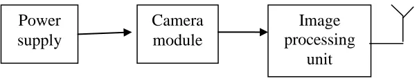
[image:3.612.189.490.371.428.2]The figure 1 shows the block diagram of video CAMinterfacing
Figure 1: Video CAM Interfacing
The power supply is given to the camera module, which is then given to the antenna after an image processing unit. It is received by a wireless CAM receiver and through TV tuner card it is given to the PC or laptop.
Power supply
Camera module
Image processing
Zigbee interfacing
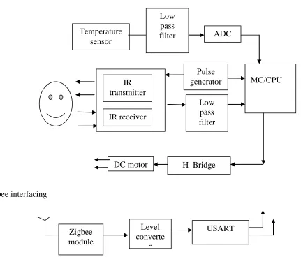
Figure 2 :Sensor, IR Transmitter And Receiver, Dc Motor And Zigbee Interfacing
The figure 2.2 shows the block diagram of temperature sensor interfacing ,IR transmitter & receiver, DC
motor interfacing, and ZIGBEE interfacing
Temperature sensor IC used is LM35.The output of the temperature sensor is given to the low
pass filter, which passes out the low frequency signals to the Analog to Digital Converter(ADC). The
temperature can be viewed in the pc/laptop using which the user controlling the rover The pulses from
the pulse generator are given to the IR transmitter. In the absence of obstacle the complete radiation
from the transmitter is obtained at the receiver .However, when the intensity of radiation from the IR
transmitter
IR receiver
Pulse generator
Low pass filter
DC motor H Bridge
MC/CPU Temperature
sensor
Low pass
filter ADC
Zigbee module
Level converte
r
transmitter to the receiver decreases the presence of the obstacle along the path is confirmed. The output
from the IR receiver is given to the low pass filter, whose output is given to the PIC microcontroller.
The zigbee module is interfaced with the microcontroller which helps in the communication between
rover and the controlling person. For the proper data transfer or communication between them there
should be a zigbee module in connection with PC/laptop. For obtaining data’s in laptop the transmitted
data by the zigbee should be converted in to serial data for this purpose the MAX232 is used with the
[image:5.612.138.518.276.421.2]zigbee module.
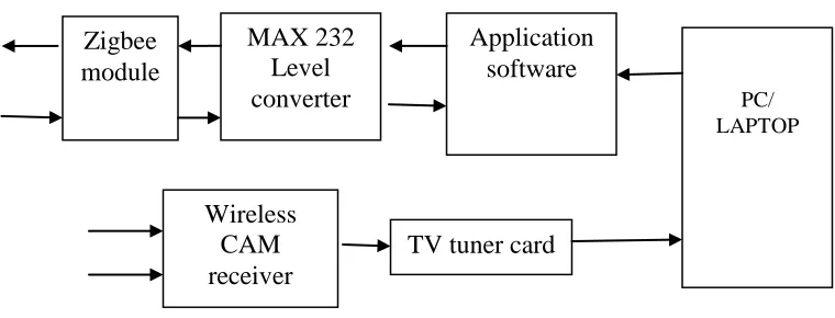
Figure 3 : Level Conversion
The figure 2.3 shows the level conversion using MAX232 for connecting ZIGBEE module and
wireless CAM receiver connected to PC/laptop.The wireless cam is interfaced in the rover for viewing
the path through which the rover is moving and the obstacles in its path. The user can view the videos in
the PC/laptop using which he controls the rover. For viewing the videos there should be the software
inside the PC/laptop, and the TV tuner card.
The figure 2.4 shows the power supply section of rover with wireless cam and zigbee Zigbee
module
MAX 232 Level converter
Application software
PC/ LAPTOP
Wireless CAM receiver
12V Vin Vout Vcc
Figure 4: Power Supply
The dc motors are used for the movements of the wheels of the rover. The input that is a high
voltage or low voltage is obtained in the dc motor through the H-bridge according to the character we
are giving through the PC/laptop. The movement depends up on the program written in the PIC16F877.
The power supply for various components such as PIC16F877, Zigbee module, DC motors are provided
with the help of regulator ICs. For the working of PIC16F877 ,5v is required a, for the zigbee module it
is 3.3v,and for DC motors the voltage required is 12v.With the help of different regulator IC s these
voltages are provided.
CIRCUIT DIAGRAM
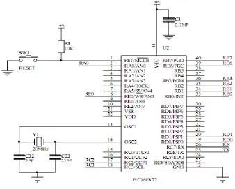
The following is the pin diagram of PIC16F877 microcontroller used in the ROVER and it has high
performance RISC CPU with an operating speed DC-20MHZ clock input.
The main components used in the circuit of the rover are PIC16F877, Zigbee, DC motor and the
wireless cam. PIC is a 40 pin IC. It has six I/O ports .A 20MHz clock is given to the PIC through pin
13 and14 using crystal oscillator. Reset switch is used for setting the PIC in different modes,ie, working
mode or programming mode. PORT A,PORT B,PORT C,PORT D, and PORT E. PORT A is a
bidirectional I/O port. It has 6 pins, out of which 5 pins are used as analog input. PORT B is also a
bidirectional I/O port. It has 8 pins and is used as external interrupt pins. PORT C is a bidirectional I/O
port and it has 8pins.
MC/CPU Regulator IC
PORTD is bidirectional I/O port when interfacing to a microprocessor bus. Analog to Digital(A/D)
converter module has 8 inputs. At a time it can accept 8 inputs. The A/D conversion of the analog input
signal results in a corresponding 10-bit digital number.
RC0,RC1,RD0,RD1, are given as the input to DC motor. Output of LM35 is given to RA0.IR
receiver output is given as the input of RE0. Depending upon the value of RA0 ,RE0,temperature and
the object is detected.
Figure 5: Pindiagram Of PIC16F877
PORTD is bidirectional I/O port when interfacing to a microprocessor bus. Analog to Digital(A/D)
converter module has 8 inputs. At a time it can accept 8 inputs. The A/D conversion of the analog input
signal results in a corresponding 10-bit digital number.RC0,RC1,RD0,RD1, are given as the input to DC
motor. Output of LM35 is given to RA0.IR receiver output is given as the input of RE0. Depending
upon the value of RA0 ,RE0,temperature and the object is detected.
[image:7.612.151.489.224.495.2]Figure 6: Power Supply
The PIC requires 5v and it is provided using the 7805 voltage regulator IC. For the Zigbee 3v supply is
required. Using LM317 ,we can provide 3 to 30v.The voltage is adjusted to 3v using a potentiometer
and resistors .For the dc motors 12v supply is required and is provided using 7812 voltage regulator
IC’s ,the capacitors used in the circuits are used for avoiding the noise in the input and output sections.
The circuit below shows the zigbee interfaced with PIC16F877
Figure7: Zigbee Interfacing
The transmitted data from the PIC to the Zigbee is of 5v, but the Zigbee works only
with 3v.So this 5v should be reduced to3v, for this purpose the resistors are used .The zener diode in the
suitable with PIC, so this is to be raised to be 5v.For this purpose transistor arrangement is used. When
the zigbee output is 3v the transistor Q1 gets turned on and Q2 get turned off so the output acrossR5 is
5v this is given to the PIC16F877. The figure below shows the H-Bridge connections used for the wheel
[image:9.612.65.551.211.382.2]movement of ROVER
Figure 8: H-Bridge
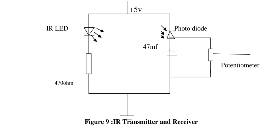
The circuit section of IR Transmitter and Receiver. This is used in the rover to identify whether its path is clear.
+5v
IR LED Photo diode
47mf
Potentiometer [image:9.612.58.532.475.701.2]
An IR LED is used for producing the IR radiations. Here a 5v dc supply is provided and the resistors and
capacitors are used for reducing the unwanted signals in the output. The receiver is a photo diode which
is used for receiving the IR radiation. According to the output voltage from the receiver we can
determine the whether there is a object near to the rover. High output voltage means the path is clear and
the low output means there is an obstacle in its path.
[image:10.612.196.417.255.436.2]The following shows the output of the mini project “ROVER WITH WIRELESS CAM AND ZIGBEE”
Figure 11: Rover With Wireless CAM And ZIGBEE (Front View)
CONCLUSION
This project Rover with wireless CAM and zigbee provides a satisfactory output. The video
obtaining in the laptop helps to identify the type of obstacle. And the temperature value gives the
information about the surrounding conditions of the rover. At present with the detection of an obstacle
the movement of rover gets stopped. But in future with certain modifications in the programming section
with the detection of an obstacle the rover can change its path .And also this can be modified in to a
rover moving according to the users voice. These rovers can be used for several applications.
REFERENCES
[1] J.J. Craig, Introduction to Robotics. Reading, MA: Addison-Wesley, 2nded., 1989
[2] Jiang Peng, Huang Qingbo, Wang Jianzhong Research on Wireless Sensor Networks Routing Protocol for Water Environment Monitoring 0-7695-2616-0/06 2006 IEEE
[3] Y. Tian, K. Xu and N. Ansari, TCP in wireless environments:problems and solutions, IEEE Communications Magazine 43 (3)(2005), :pp 27–32.
[4] J. Gao, D. Xu, N. Zhao and W. Yan, "A potential field method for bottom navigation of autonomous underwater vehicles", Intelligent Control &Automation, 7th World Congress on WCICA, pp.7466-7470, 2008.
[5] J. Gao, D. Xu, N. Zhao and W. Yan, "A potential field method for bottom
navigation of autonomous underwater vehicles", Intelligent Control &Automation, 7th World Congress on WCICA, pp.7466-7470, 2008.
[6] Amitab Maurya, Data Mining Technique With Crossbreeding Neural Network: Lvq And Hopfield, Scholedge International Journal Of Multidisciplinary & Allied Studies, Vol.1,Nov.Issue;
www.scholedge.org
[6] LPC2106 datasheet. http://www.alldatasheet.com/datasheetpdf/pdf/83951/PHILIPS/LPC2106.html. [7] Y. Tian, K. Xu and N. Ansari, TCP in wireless environments:problems and solutions, IEEE Communications Magazine 43 (3)