Non-Destructive Analysis of FSW Process and
Comparison with Simulation and Microstructural
Analysis
T. Pavan Kumar1, P. Prabhakar Reddy2
1
Rayalaseema University, Kurnool,51800, India
2
CBIT, Hyderabad, 500075,India
Abstract: Friction Stir Welding is an evolving metal joining technique and is mostly used in joining materials which cannot be easily joined by other available welding techniques. It is a technique which can be used for welding dissimilar materials also. The strength of the weld joint is determined by the way in which these material are mixing with each other, since we are not using any filler material for the welding process the intermixing has a significant importance. The complication with the friction stir welding process is that there are many process parameters which effect this intermixing process such as tool geometry, rotating speed of the tool, transverse speed etc., in this study an attempt is made to compare the material flow and weld quality of various weldments by changing the parameters. Ultrasonic signal Analysis is used to characterize the microstructure of the weldments. use of ultrasonic waves is a non destructive, accurate and fast way of characterization of microstructure. In this method the relationship between the ultrasonic measured parameters and microstructures are evaluated using background echo and backscattered signal process techniques. The ultrasonic velocity and attenuation measurements are dependent on the elastic modulus and any change in the microstructure is reflected in the ultrasonic velocity. To compare the influence of tool geometry on the material flow behaviour various tool pin profiles are considered and the resulting velocity distributions are compared. The results obtained revealed the tool pin geometry has a considerable effect on the weld nugget zone.
Keywords: Non-Destructive Analysis; Friction Stir Welding; Ultrasonic Signal Analysi;, Simulation;, Microstructure;
I. INTRODUCTION
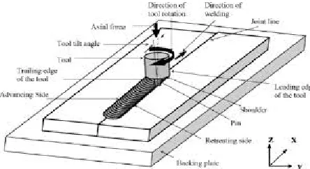
[image:2.612.195.417.602.723.2]Friction Stir welding process is a significant metal joining process since its invention by The Welding Institute(TWI) in 1991[1].Friction Stir welding process is a joining process which uses a tool which rotates and travels along the joining surfaces which are clamped together. The tool is non-consumable and many types of tool profiles can be employed for the welding purpose. Tool geometry is defined by the shoulder diameter, pin diameter, profile of pin and the pin length. The pin length is usually shorter than then the thickness of the plates. The pin is penetrated into the work pieces and the tool rotates and transverses along the centreline. The interaction that takes place between the tool & work piece gives rise to friction generating heat which in turn creates plastic deformation and the flow takes place in plasticized state as the tool traverses forward [2].the process is illustrated in the Fig The material flow in friction stir welding is complex in nature and mainly depends on the tool geometry& other process parameters viz. tool rotation speed, traverse speed of welding, tilt angle of the tool, axial force applied and properties of the material to be welded. The weld formation depends on the material flow behaviour of the materials to be welded. As friction stir welding is a fusion welding process the welding takes place due to the intermixing of the materials for which material flow is the primary criteria.
2026
©IJRASET (UGC Approved Journal): All Rights are Reserved
Understanding of the mechanics of flow pattern and material flow characterizations during the friction stir are very much essential for proper tool selection and the process parameters for the purpose of welding [3].researchers made contributions to describe the material flow characterizations and describe the mechanics involved in it. Material flow process during the friction stir welding process is explained by employing a marker which is inserted into work pieces which described the material flow in the weld zone [4].some researchers tried to describe the material flow using 2D flow modelling around the tool pin [5-6].CFD was used by researchers to describe the 3D model flow also [7].Tool geometry plays a crucial role and defines and dictates material flow path in friction stir welding process [8].The advantage of the friction stir welding process is that it eliminates various metallurgical problems like porosity, spatter etc., and also an environmental friendly As friction stir welding is a hybrid thermo mechanical process the weld zone is divided into different zones namely Base Metal zone(BMZ),Heat affected ZONE(HAZ) and thermo mechanically affected zone(TMAZ).BMZ has no microstructural changes, no plastic deformation takes place in the HAZ but due to the heat generated microstructural changes occur in the HAZ region..notable microstructural changes are observed in TMAZ [9-12]. The properties of the welded joint are affected by the temperatures due to the heat generation during the process which is due to the friction between the tool surface and the work piece.
II. MATERIALS&METHODOLOGY
A. Experimentation
During this study 8mm sheets of AA 6061 are welded to 8mm The chemical of the material composition and tool description are tabulated in the Table 1 and Table 2.
TABLE I
COMPOSITION OF AA 6061
Element Al Mg Si Cu Cr
Amount (wt %)
Bal. 1.0 0.6 0.3 0.2
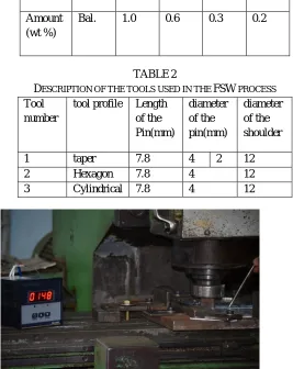
TABLE 2
DESCRIPTION OF THE TOOLS USED IN THE FSW PROCESS Tool
number
tool profile Length of the Pin(mm) diameter of the pin(mm) diameter of the shoulder
1 taper 7.8 4 2 12
2 Hexagon 7.8 4 12
3 Cylindrical 7.8 4 12
Fig. 2 Friction stir welding experimental setup with provision to measure temperatures using thermocouples
[image:3.612.165.432.366.702.2]to hold the 100mmX200mmX8mm plates and clamed firmly. Experiments are conducted using tools of varying tool pin profiles to estimate the impact of the tool pin profile on the weld strength. Taper, hexagonal and cylindrical tool profiles are used for the welding purpose and comparison of the mechanical and macrostructures properties is done. The process parameters for tool profiles are kept constant as follows the tool rotational speed of 1400rpm and welding speed of 60mm/min. Temperatures are measured using K-type thermocouples during the welding process to estimate the heat generated during the friction stir welding process using different profiles
B. Process Modelling
Eulerian flow formulation is adapted in the process modelling of friction stir welding with the following assumptions
1) As we are considering aluminium as the material the elastic behaviour and strain hardening are neglected to keep in view the high strains expected in the case of aluminium alloys during FSW
2) the Fluid flow that occurs during the FSW process is attributed to the pure plastic deformation without strain hardening 3) flow stress of the material is modelling using Zener-Hollomon equation
4) fluid flow is considered as laminar this is due to the high temperatures which are generated near the pin resulting in high rates and viscosity due to which calculated Reynolds numbers are very small.
5) The 3-dimensional material flow that happens during the FSW process is modelled mathematically as a steady-state laminar flow happening around the rotating pin considering the fluid as an incompressible and non-Newtonian and the material is flowing through a stationary discredited flow zone a stationary mesh instead of moving mesh is considered The heat generated is attributed to the viscous dissipation inside the fluid.
6) in this study, a validated model of the FSW process was generated using the CFD software FLUENT, with this model then being used to assess in detail the differences in flow behaviour, mechanically affected zone (MAZ) size and strain rate distribution around the tool for various tool geometries
C. Mechanism of Friction stir Welding Process
The friction stir welding process generally involves three stages plunging of the tool, tool traverse and retraction of the tool from the work piece. Initially the tool is plunged in to the work piece till the surface of the shoulder of the tool touches the surface of the wok piece. Once the preheating time is elapsed the tool slowly traverses forward till the end of the work piece is reached and tool is retracted from the work piece leaving a hole at the end of the weld. All the three phases of the mechanism have physical significance as they influence the temperature distribution which in turn affects the material flow pattern and resulting microstructure.
Fig.3. Digital image of the welded Plate
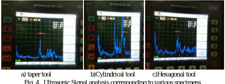
D. Characterization of weld quality using ultrasonic signal analysis
Ultrasonic signal Analysis is used to characterize the microstructure of the elements. Use of ultrasonic waves is a non destructive, accurate and fast way of characterization of microstructure. In this method the relationship between the ultrasonic measured parameters and microstructures are evaluated using background echo and backscattered signal process techniques. The ultrasonic velocity and attenuation measurements are dependent on the elastic modulus and any change in the microstructure is reflected in the ultrasonic velocity.
2028
©IJRASET (UGC Approved Journal): All Rights are Reserved
a) taper tool b)Cylindrical tool c)Hexagonal tool Fig. 4. Ultrasonic Signal analysis corresponding to various specimens
III. RESULTSANDDISCUSSIONS
To determine the flow behaviour of the material with change in tool geometry without altering other process parameters as mentioned above.fig. 5a,5b,5c show the meshing model of various tool geometries viz. cylindrical, hexagonal and tapered tools. similar boundary conditions are chosen for all the simulations and various contours are plotted to observe the difference I patterns.
a) Cylindrical tool b)Hexagonal tool cTaper tool Fig.5. Meshing model of FSW process with various Tools
Fig 6a,6b & 6c show stream lines which are different for different tool geometries .
Uniform stream lines are observed for the hexagonal which is attributed to the symmetrical edges which force the material around the tool uniformly
a) Cylindrical tool b) Hexagonal tool cTaper tool Fig. 6. stream lines of FSW process with various Tools
a) Cylindrical tool b) Hexagonal tool cTaper tool Fig.7. Images obtained using SEM at fracture zone corresponding to various tools
[image:5.612.127.486.77.211.2]Fig.8 a. Macrostructure of the FSW weld zone obtained with Hexagonal tool
Fig.8 b. Microstructure of the FSW weld zone obtained Fig.8 c. Grain size distribution according to plainimetric with Hexagonal tool method of the FSW weld zonobtained with Hexagonal tool
Micro structural studies are conducted for correlating the results with the simulation results. Fig 8 a,8b,& 8c show the Macrostructure of the FSW weld zone obtained with Hexagonal tool, Microstructure of the FSW weld zone obtained with Hexagonal tool and Grain size distribution according to plainimetric method of the FSW weld zone obtained with Hexagonal tool.
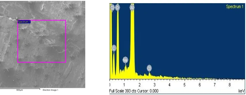
Fig. 9.EDS Studies of the specimen-hexagonal Tool
[image:6.612.99.526.514.679.2]2030
©IJRASET (UGC Approved Journal): All Rights are Reserved
IV. CONCLUSIONS
The study shows that there are significant differences in the flow behaviour around
and under the tool when the tool geometry is changed and it shows that the proposed approach is able to predict flow around the FSW tool. Good correlation is found between the simulation results and the experimental results and hexagonal tool yields good results compared with cylindrical and tapered tools.
REFERENCES
[1] W.M.Thomas,.D.Nicholas.J.C.needham,M.G.murch,P.Templesmith and C J ,Dawes,G.B.Patent Application 91259788,Uk Patent office,London 1991. [2] R.S.Mishra,and Z.Y.Ma,”Friction stir welding and Processing”Mter Sci Eng R,50 pp 1-78,2005.eidel T U,reyonolds A P,”Visualisation of material flow in
AA2195 friction stir welds using a marker technique,Matallurgical and Material TransactionA,2001:2879-2884
[3] Siedel T U ,Reynolds A P “ Two dimensional .friction stir welding processmodel based on fluid mechanics.Science and Technology of Welding and Joining 2003,:175-183
[4] Colegrove P A ,Shercliff H R ‘ Development of Trivex friction Stir Welding tool part 2 three dimensional flow modeling” Science and Technology of Welding and joining ,2004:483-492
[5] Schmidt H,Hattel J “ Modelling heat flow around the tool probe in friction Stir welding “Science and Technology of Welding and joining,2005:1176-186 [6] Colegrove p A,Shercloff h R .’3 D CFD modeling of flow round a threaded friction stir welding tool profile “ journal of material Processing and
Technology,2005,:320-327.
[7] Colegrove P A ,Shercloff H.R”CFD modeling of Friction stir Welding of thick plate 7449 alluminium alloy” Science and Technology of welding and joining 2006,;429-441
[8] G.lin,L E Murr,C S niou,J C ,mcclure,ER vega” Microstructural aspects of the friction Stir Welding of 6061-t6 aliminium ‘ Scripta materilica (1997)335-361. [9] C.G.rhodes,M W.Mohany, W H Bignet,R.A.Spurling,C C Bampton’Effects of friction Stir Welding on Microstructure of 7075 aluminium” Scripta aterilca
(1997);69-75
[10] O.v.Flores ,c kennedy,l E Murr,D Brown,S Pappu,B M nowak,j C Mcclure”Microstructuralissues in a Friction stir Welded aluminum alloy “Scripta Mechanica (1998)703-708