Research for Multi-sensor Information Fusion
Algorithm of Search and Rescue Robot Based on
Embedded Control Network
Peng WangSchool of Mechanical & Power Engineering, Harbin University of Science and Technology, Harbin, China Email: wp_hust@ yahoo.com.cn
Wenhao Jiang , Xin Li , Shaochen Kang and Jinglei Xin
School of Mechanical & Power Engineering, Harbin University of Science and Technology, Harbin, China Email: [email protected]
Abstract—Aiming at completing search task under disaster condition problems, an optimizing strategy based on multi-sensor information fusion is proposed in this paper. Firstly, search and rescue robot control system hardware circuit is designed; secondly, embedded system software design is realized; and then, a polymerization Kalman filtering model is proposed, it uses local Kalman filter weights scheduling principle to improve system fault-tolerant ability and overall fusion performance. What’s more, Adaboost algorithm realizes the multi-sensor information optimal fusion. Through simulation test experiment, the robot search traversal ability is verified under unstructured environment.
Index Terms—polymerization Kalman filter, information fusion, search and rescue robot, embedded system
I. INTRODUCTION
The world suffers massive natural and man-made disasters every year [1]. These tremendous disasters cause many buildings collapsed and casualties, when the disasters occur, the most urgent thing is to search and rescue those survivors trapped in the ruins [2]. Study demonstrates that the best rescue time is within 48 hours [3]. However, the complex and dangerous disasters sites bring huge threats to rescuers and survivors, which delay the rescue operation [4].
The inflammables and explosives objects and wind cause big fire easily during the disasters [5]. In some dangerous regions, such as nuclear power station, chemical plant and so on [6], if there are no corresponding protections or supports, the well-trained professional rescue workers can not work easily, however, when they wear protective outfits, their environment perceptions are limited [7], so the rescue work processes are postponed.
At present, search dogs are the most useful tools to search with human body odour, but there are many unavoidable problems [8]. According to the research material from the experienced Russian search dogs training corps, generally speaking, a qualified search dog
is trained needs at least 1.5 years, while its effective working time is 3 years at most [9]. In the work, the total time can not over 2 hours [10]; the continuous working time must not exceed 30 minutes, or its smell sensitivity will reduce because of the exhausted [11]. This defect can’t be accepted in the urgent rescue processes while the living body search and rescue robots relying on dogs have the same problem [12]. In the west, the fee that supporting, training and using a search dog is $40,000 annually, however, search dogs instinctively flee when the search and rescue scenes have dangerous gases [13]. The search and rescue robot based on multi-sensor information fusion can solve the problems well [14].
The mobile robot technologies that navigation and location, path planning, map building and unknown environment exploring under indoor structured environment are basically mature through long-term study [15], but the complex and unknown unstructured environment of disaster scenes still needs further study. Currently, the main control mode of search and rescue robot is manual operation, the totally autonomy is not achieved. Autonomous mobile robot needs multi-sensor fusion to perceive the environment information. It can move along the specified path depending on the single road sign which is arranged simply and owning high flexibility. But the images captured by camera are easy to be effected by rays, so it’s hard to build environment model. Under complex environment, especially, when the color of background and obstacle is similar, judging the obstacle around is difficult. While the ultrasonic sensor array can recover the shortage and provide the distance information, however, for the existing error, it can’t get the accuracy direction of the goal.
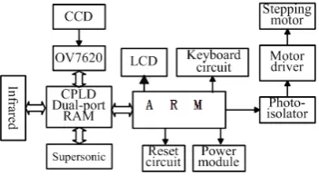
Figure 1. Structure of the mobile robot.
Figure 2. Architecture of control system.
obstacle avoidance of autonomous multi mobile robots. The polymerization Kalman filtering optimal fusion is realized based on Adaboost algorithm.
II. DESIGN OF MOBILE ROBOT AND SYSTEM
ARCHITECTURE
A. Robot Structure Design
Driving wheels set of search and rescue robot is symmetrical,and two directive wheels is too (Fig.1).
Each wheel has the relative organism center position in the system, also has the posture angle. Various design parameter and movement parameters are defined. If the system Jacobian matrix of inverse kinematics is not full rank, there is singularity in the mobile robot system according to the robot kinematics principle. The degree of freedom will be reduced for the mobile robot. In order to ensure that there is three degrees of freedom movement for the system, the system Jacobian matrix of inverse kinematics must be full rank (rank=3).
B. Control System Architecture
The kernel of search and rescue robot control was the LPC2210 and the CPLD chip EPM7128SLC84 of company Altera. LPC2210 implemented the function of real-time controlling exactly the trace and position of motor, triggering and control CCD image sensor, detecting the state of infrared sensor and supersonic sensor and so forth. In the mobile robot system, the large numbers of sensor information can exchange data rapidly and realize the interface. We utilized CPLD to realize the function of dual-port RAM and it solved mentioned above problems. The dual-port RAM has two absolute independent data bus, address bus and control bus. It allowed two separate systems to visit the dual-port memorizer at the meantime, so it actualized the high speed communication, and enhanced the accuracy of write and read operation. The architecture of control system is shown in Fig.2.
III. EMBEDDED CONTROL SYSTEM HARDWARE DESIGN
A. ARM Microprocessor Selection and Analysis
The embedded system hardware core component is micro controller; generally, the processor word length is 32 bits. The embedded system mentioned at present mainly is the system organized by 16/32-bit (especially the latter) RISC architectures microprocessor/micro-controller, to distinguish from the early 8-bit microcontrollers system.
LPC2210 is ARM7TDMI-S core chip produced by PHILIPS Company, and it has all the advantages of ARM processor: low-power and high-performance, meanwhile it has very rich chip resources, so it is an ARM chip with high performance price ratio, which is suitable for embedded product development. Its main features are: 1. On chip Boot loading program realizes in system programming and in application programming, flash programming time: 512 bytes are programmed in 1ms, sector erasing or full wafer erasing just needs 400ms; 2. EmbeddedICE-RT interfaces enable breakpoints and points. When foreground task uses on chip RealMonitor to debug, interrupt service routine can continue to execute; 3. Embedded for tracking macro unit supports high speed and real time tracking executable code without interference; 4. Vector interrupt controller can configure priority and vector address.
B. Reset State and Reset Circuit Design
When LPC2210 is under RESET pins effective level control, program counter (PC) and special function register are in the RESET condition. Its internal each function component is subject to the special function register, and the program counter commands the program running directly. Register reset state determines its internal relevant function component initial status. After reset, PC is 0x00000000, so program entrance address is 0x00000000. Namely, when the system starts, CPU reads startup code from reset address 0x00000000 firstly, and after the system resets, for LPC2210 system, all registers values are not sure except for PC and CPSR. CPSR is forced to turn into b10011, its I bit and F bit are set, T bit is cleared, and return ARM state and recover execution; PC fetches instruction beginning from the address 0x00000000 to the next instruction.
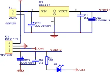
Figure 3. Power circuit
C. Power Circuit Design
In the system, LPC2210 needs 3.3V dc stabilized power supply, and some other devices need 5.0V dc stabilized power supply, in order to simplify system power circuit design, high quality stabilized power supply 3.3V and 5.0V are required. 5.0V power supply isolated by B0505LS isolation device, is supplied in RS485 communication circuit, makes RS485 circuit and other parts supply power and connect ground separately, to reduce RS485 communication interference, system power circuit is shown as figure 3. AS1117 is selected as DC-DC converter, which can complete the conversion from 5.0V to 3.3V, its characteristics are big output current, high precision output voltage, high stability. Some large capacitance electrolytic capacitors are placed at PCB power entrance end and power input and output pins of power supply changeover chip to improve the stability of power input and output. The right capacitance values, which are combined with the selected power supply chip reference circuit, are given to complete capacitance choice.
D. JTAG Interface Circuit
Joint Test Action Group is an international standard test protocol, which is mainly used for chip internal testing, system simulation and debugging, it is an embedded debugging technology, and the special test circuit TAP (Test Access Port) is packed in the chip, the internal nodes are tested by the special JTAG test tool. Currently, the most of complex components support JTAG protocol, such as the ARM, DSP, FPGA and etc devices. The standard JTAG interface is 4-wire connection: TMS, TCK, TDI and TDO are test mode selection, test clock, test data input and test data output respectively. ARM7TDMI debugging interface bases on the IEEE standard 1149.1-1990 and standard test access port and boundary scan system structure, it contains hardware expansion with advanced debugging characteristics, ARM standard embedded ICE (in-circuit emulator), which gets support through JTAG/ICE. All the components on chip can be visited through JTAG interface, which is often used to realize the system programming function, such as programming for FLASH device and etc. The special ICE pins: TDI, TDO, TCK and TMS for LPC2210 realize ARM7TDMI ICE interface, which provides a complete and low cost
debugging scheme for target board simulation. This system uses a 20-pin standard JTAG interface .
E. Communication Interface Circuit Design
RS485 transceiver adopts balance send and differential reception. Namely, drive converts TTL level signal into differential signal output at sending end; receiver converts differential signal into TTL level, so it can restrain common-mode interference ability. This system chooses American TI company RS485 interface chip of SN75LBC184 to design and develop, it is compatible with differential data transceiver commercial standard, on chip A and B pins connect with high-energy transients interference protection device, which can withstand the peak value for 400 overvoltage transient, such as lightning, electrostatic discharge and alternating current fault, thus to significantly improve the device resistance reliability for over-voltage transient, its driver and accept function table are shown as figure . The ordinary RS485 transceiver is damaged easily by over-voltage transient and if we want to protect effectively, normally, the protection devices like isolated transformers are needed. If we use SN75LBC184, transmission line can be connected directly without any protection component, and it provides a reliable, low cost and simple design scheme. SN75LBC184 integrates all the precautionary measures into a chip for various faults in RS485 communication, including transient voltage, electromagnetic interference, bus open circuit, hot stoppage and etc. SN75LBC184 can effectively restrain the transient voltage like lightning and etc.
F. Ultrasonic Distance Measurement Circuit Design This Ultrasonic Ranging Module is a precision electronic measurement device which includes an interface electronics module and two ultrasonic transducers, depending on the model selected. The ranging module provides the OEM with a PWM Latch output pulse, whose duration is proportional to the time required for the sound to travel between the transmit and receive transducers. The latch pulse width may be processed through additional circuitry for applications requiring position, level, profile, or thickness measurements. Internally or externally triggered, target distance ultimately limits the maximum pulse repetition rate. A maximum rate of 150 Hz is possible when targets are less than one foot distant; refer to individual module specifications for rep rate limits. For internal triggering, the pulse repetition rate is set via a single external resistor.
IV. CONTROL SYSTEM SOFTWARE DESIGN
A. ARM Assembly Language Program Structure
in LR for PC. ARM architecture supports C/C++ and assembly language mixing programming. In a whole program design, the main programming tasks are completed by C/C++, besides the initialization part, which is finished by assembly language. When the program is executed, initialization process should be completed firstly, and then jump to C/C++ program code, generally, there is no parameter transmission between assembler and C/C++ program.
HEF4094 and 74HC595 are serial-in parallel-out shift register, obviously, the serial port drive is applied, but serial port resource of S3C44BOX is limited, which is needed to communicate with upper computer, so the parallel I/O port is modeled as a serial port method to solve the problem above. So 4 parallel I/O ports can complete the program display task, the 4 I/O ports, from PORTD0 to PORTD3, are used in the program, while PORTD is composed by 8 I/O ports.
B. Task Scheduling
μCOS-Ⅱ is a real time operating system with
preemptive kernel. The real time operating system (RTOS) is a section background program which is executed firstly, when the embedded system starts. The user application program is the task running on RTOS. According to various tasks, RTOS does resource management, information management, task scheduling exception handling and etc. Preemptive kernel means a running task makes a higher priority task ready, then the running task will abdicate CPU control right. If the subroutine is interrupted to make a higher priority task ready, when the interrupt is completed, the interrupt task is hung, and the high priority task is executed.
Each task is an infinite loop, may be in one of the following 5 kinds of states: dormancy state, ready state, running state, hang up state and interrupted state. Dormancy state means the task resides in internal memorizer, but can not be scheduled by multitask kernel; Ready state means that the task is ready, it can run right now, but because its task priority is lower than the running task’s, it still unable to run; Running mode means the task masters CPU control right, it is running; Hang up state can be called as wait event, means the task is waiting for some certain event happens, finally, when the interruption happens, CPU provides the corresponding interrupt service, while the running task doesn't work temporarily, which enters the interrupted state.
C. ARM System Initialization Process
LPC2210 is the complex on chip system based on ARM chip, its hardware modules are configurable, and the needed working condition should be set by software. So, a special section startup codes are needed to complete the system initialization before application program starts. Because this kind of codes is directly programmed for the processor kernel and hardware controller, usually, assembly language is used. The general operations executed by system startup procedure include the following steps:
1) Set program entry pointer;
2) Set interrupt vector table; 3) Initialize storage system;
4) Initialize CPU various modes stacks and registers; 5) Initialize various kinds of internal and external chip peripherals used in target system;
6) Initialize user program execution environment; 7) Lead the main application program.
ARM requests interrupt vector table must be placed at address 0 to start in the continuous 8×4 bytes space. When an interrupt occurs, ARM forcedly places PC pointer at corresponding interrupt type address value in vector table, because each interrupt only occupies 1 byte memorizer space in vector table, only 1 ARM can be placed, the jump instruction is placed in vector table which makes the program can jump from vector table to memorizer to execute interrupt handling.
The systematic memorizer controller is the programming object of initialized memorizer system. FLASH and SRAM belong to static memory, they can share the same memorizer port, while SDRAM has the features that dynamic refresh and address lines multiplex, usually, equipped with a special memorizer port. When the system is power on, the program is executed automatically from address 0, so the right code must be ensured at address 0 in the original state, namely the nonvolatile ROM or FLASH is required at address 0. But, ROM or FLASH access speed is relatively slow, each interrupt occurs, the vector table on ROM or FLASH is read firstly, which affects the interrupt response speed, so the system provides a memory remap method, which can point address 0 to RAM, and then execute the instruction in RAM space.
Some basic initialization should be done for target system before entering main() function to ensure LPC2210 can work, for example, LPC2210 has different memorizer mapping way, which should be set according to hardware; To avoid confusion, the clocks of all the parts in system had better be set before entering the main() function, the key codes are shown as below:
#ifdef__DEBUG MEMMAP=0x3;
#endif
#ifdef__IN_CHIP MEMMAP=0x1;
#endif PLLCON=1;
#if(Fpclk/(Fcclk/4))==4 VPBDIV=1;
#endif
#if(Fcco/Fcclk)==4
PLLCFG=((Fcclk/Fosc)-1)|(1<<5);
#endif
When the whole initialization work is completed, call the __main provided by ADS, __main is a function provided by the compiling system of ADS, responsible for the initializations of C runtime library and application program execution environment, finally, automatically jump to the user's main() function.
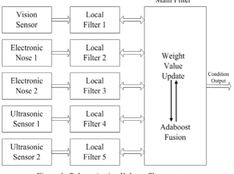
Figure 4. Polymerization Kalman filter structure.
A. Data Fusion Technology
Data Fusion technology namely multi-sensor information fusion technology, and its basic purpose is to obtain more information than single sensor through various of sensors data comprehensive treatment, to educe the new and meaningful information, which is more valuable than the single one’s, and it is helpful for judgment and decision making. In the multi-sensor information fusion system, commonly, the information provided by each sensor is incomplete, inaccurate, fuzzy and even conflicting, namely a lot of uncertainties are contained, so the information fusion process is an uncertainty reasoning and decision process to achieve the purpose of target identification and attributes judgment.
A lot of different data fusion algorithms are proposed, aiming at the uncertainty processing of multi-sensor fusion. Kalman filtering algorithm is a typical delegate. B. Kalman Filter
Kalman filter is an optimal estimation technology, in engineering problems, in order to understand the numerical value of each physical quantity (namely the quantity of state in filter, usually, it is a random quantity) of engineering objects (namely the system in filter), or in order to control engineering object, each system state must be measured through measurement method, but the measured value may be only part of the system state or linear combination of part states, and the measured value contains random error (namely the measurement noise). In order to solve this problem, usually optimal estimation is proposed. The optimal estimation is to dispose measurements related with part of state according to some optimality criterion, to get more state estimation valuations with the smallest error under the criteria. There are different kinds of optimal estimations with different criteria and estimation methods. While Kalman filtering is a recursion linear minimum variance estimation, its estimation is unbiased if the right filter initial value is chosen. When Kalman filtering is used to do the optimal estimation, first of all, the kinetic model should be established, namely system state equations and measurement equations, what’s more, they must be linear. However, in engineering practice, system often can not be described with the simple linear model, generally, the extended Kalman filtering(EKF) is used for the nonlinear system, which makes the nonlinear state equations and the measurement equations linear, and then to process them with Kalman filtering method, thus EKF method is a kind of quasi optimal estimation.
In order to adapt to the nonlinear system model, in scattered filtering, the standard centralized kalman filter is divided into many local filters and a master filter corresponding to each sensor, the local filters work parallel, their outputs (namely state estimations) are periodically fused by a master filter, and then a whole state estimation is produced. This scattered Kalman filter can significantly reduce the calculated amount of the whole filtering system, but it caused the whole Kalman
filter is subprime state estimation. Scattered Kalman filter technology not only reduces the system calculated amount, but also makes the whole multi-sensor system has certain fault-tolerant ability.
The special scattered Kalman filter-polymerization Kalman filter is proposed in this paper according to the traditional scatter principle, it uses weights scheduling principle in the local Kalman filter, which can further improve the system fault-tolerant ability and the overall performance, while the multi-sensor system information fusion and the fault-tolerant performance are analyzed. C. Polymerization Kalman Filter Design
Polymerization Kalman filter structure mainly has two aspects, the first is the data scatter processing; the second is the scatter processed data is fused globally. Polymerization filter is a block estimation and two-step cascade data processing technology. Its basic structure shown as figure, the external sensors include 1 visual sensor, 2 smell sensors and 2 ultrasonic sensors, and 5 local filters related with the 5 sensors output local optimal estimations, while the master filter orderly processes and combines all the local outputs, to give the globally optimal state estimation. Polymerization Kalman filter
information sharing principle: (1) The total system information is properly distributed in several block filters; (2) The distributed information fused with of local sensors information to update local sensors information; (3) The updated information is recombined to be the new total information. The "information" contains all results of the filter, including state vectors, variance matrixes, inverse matrixes and etc.
D. Polymerization Kalman Filter Workflow
The workflow block diagram of polymerization kalman filter is shown as figure, the work mode and weights scheduling principle of federated kalman filter are fully reflected in the figure.
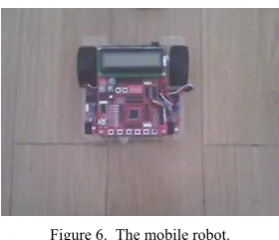
Figure 6. The mobile robot. Figure 5. Polymerization Kalman filter workflow.
Adaboost algorithm is a classifier algorithm, its basic idea is to use a lot of classifiers; the weak classifiers are stacked through certain method to constitute a strong classifier, and then several strong classifiers are installed in series to be the grading classifiers to complete more information optimal fusion search, eventually, the series of classifier relies on the system requirements for the error rate and the recognition speed.
AdaBoost is a gradually increasing way to increase functions, and its weights are calculated, while the
parameters and the weights of the added basic functions are not be adjusted.
Assume the
T
−
1
th mode:f
( )
x
a
h
( )
x
T
t t t
T
∑
−
= −
=
1
1
1 .
When the loss function is
L
(
y
,
f
( )
x
)
=
exp
(
−
yf
( )
x
)
, the new added basic function ish
T and its weight isa
T at stepT
make the training error minimum, namely(
)
∑
(
( )
)
=
−
=
Ni
i i T
i T
T
a
w
ay
h
x
h
1
exp
min
arg
,
. (1)Where
(
i T( )
i)
T
i
y
f
x
w
=
exp
−
−1 ,w
iT doesn’tdepend on
a
,
h
, sow
iT can be taken as the weight used in each observing, and the weight depends onf
T−1( )
x
i , so every sample weight changes with every iteration.The problem above can be realized by two steps: The first step: choose a weak classifier
h
T with theminimum error rate
(
i( )
i)
N
i T i
T
w
I
y
h
x
h
=
∑
≠
=1
min
arg
.The second step: ensure its weight
a
T. Whereε
T is error rate.
⎟⎟
⎠
⎞
⎜⎜
⎝
⎛
−
=
T T T
a
ε
ε
1
ln
2
1
. (2)F. Polymerization Kalman Filter Fault-tolerant Analysis The fault-tolerant means system fault detection ability, segregation ability and recovery ability. In fault-tolerance integrated navigation system design, polymerization filter plays the key role, so it is necessary to analysis various structures of composite filter more deeply, and compare with the kalman filter fault-tolerance.
Kalman filter fault recovery ability is not strong. When the fault sensor is isolated, the faultless sensor measurement information is reused for system reconstruction trouble-free, but the polluted filter information should be restored to normal. That needs to reinitialize the kalman filter whose fault sensor is isolated, so there is a period of time for the system to get right, namely the system can't work immediately. Fault recovery ability is not strong. The polymerization filter fault-tolerant performance is much better comparing with kalman, and the mainly manifested aspects as following:
Because the master filter data fusion cycle can be longer than the subfilter cycle, there is a long time to develop filter to detect soft fault before fusion.
The subfilter sensors error state estimations are separated, so the error state will not be affected by other sensors in the subfilter cycle, the effect only appears after a long time fusion cycle.
When a sensor fault is detected and isolated, the other normal subfilter state estimations still exist, so these normal estimations are fused simply to get system global estimation. System reconstruction is simple, meanwhile, fault recovery ability is strong.
The master filter can use a more accurate system model than subfilter’s, so the system fault detection ability is improved.
VI. EXPERIMENT AND ANALYSIS
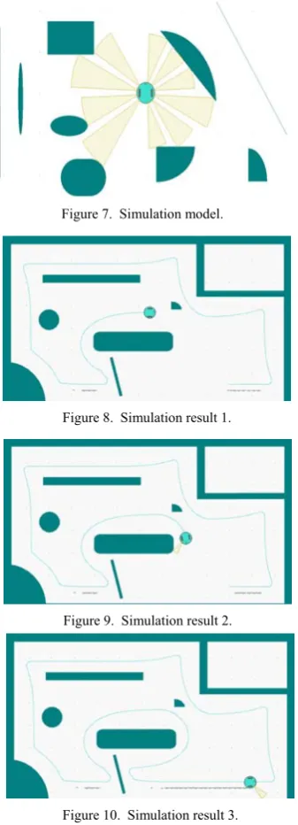
Figure 7. Simulation model.
Figure 8. Simulation result 1.
Figure 9. Simulation result 2.
Figure 10. Simulation result 3.
in the gearbox, in order to meet the requirement of changing velocity, one must be extra small and the other one must be extra big, which not only wastes the space, but also requires the small one owning high performance index. So we adopt multiple gearing to meet the ideal transmission ratio, and change its velocity step by step until the velocity of the output axis satisfies the needed index.
The simulation model is set up in c# platform. In unstructured surrounding, the autonomous search and rescue robot based on multi-sensor information fusion is considered a green bug. It can feel the around obstacles through multiple sensors. Yellow fan area of figure 7 show that the test effective range of a sensor. Whole simulation experiment of the mobile robot is shown as Fig 8-10.
The result shows that the robot is effectively moving. Embarks from the initial station, traversal all barriers, returns to the initial station finally by the most short-path.
Green thin line is the trajectory of the robot walking. From the moving trajectory of the mobile robot we can see, the fusion method can realize real-time and fast motion under the condition of that, without collision and all the obstacles are traversal.
VII. CONCLUSIONS
Information fusion technology application in navigation and positioning technology of search and rescue robot is discussed in this paper. Firstly search and rescue robot control system design is studied under unstructured environment, and polymerization filter is used for multi-sensor information inputting, which is used in integrated navigation system. The results of computer simulation and actual testing show that, the results of this search method is more accurate, namely, the single ultrasonic sensor positioning error is overcame, and the visual system error divergent is made up.
ACKNOWLEDGMENT
This project is supported by China Postdoctoral Science Foundation funded project (20100480976) and Postdoctoral Foundation of Heilongjiang Province (LBH-Z09212). The authors would like to thank Harbin University of Science and Technology for supporting this work. The authors would also like to thank the editors and reviewers for their valuable comments and for making the paper more readable.
REFERENCES
[1] Y. Gu, “Research On Optimization Of Relief Supplies Distribution Aimed To Minimize Disaster Losses,”
Journal of Computers, vol. 6(3), pp. 603–609, 2011.
[2] L. Srikanthan, “High-speed Environment Representation Scheme for Dynamic Path Planning,” Journal of Intelligent and Robotic Systems, vol. 32(3), pp. 307–319, 2001.
[3] R. Kimmel, Sethian and James, “Optimal Algorithm for Shape from Shading and Path Planning,” Journal of Mathematical Imaging and Vision, vol. 14(3), pp. 237–
244, 2001.
[4] H.Choset, “Coverage for Robotics—A Survey of Recent Results,” Annals of Mathematics and Artificial Intelligence, vol. 31, pp. 113–126, 2001.
[5] K.Liu, W.Meng and F.Bo, “IBotGuard:an Internet-based Intelligent Robot Security System Using Invariant Face Recognition against Intruder,” IEEE Transaction on Systems,Man and Cybernetics,Part C, vol. 35(2), pp. 97–
105, 2005.
[6] H.R.Everett, “Robotic Security Systems,” IEEE Instrumentation & Measurement Magazine, vol. 6(11), pp.
30–34, 2003.
[7] H.Choset, and P.Pignon, “Coverage of Known Spaces:The Boustrophedon Cellular Decomposition,” Autonomous Robotics, vol. 9, pp. 247–253, 2000.
[8] Y. Hiroaki, “A distributed motion coordination strategy for multiple nonholonomic mobile robots in cooperative hunting operations,” Robotics and Systems, vol. 43, pp.
257–282, 2003.
[9] D. Lowe, “Distinctive Image Features from Scale Invariant key points,” International Journal of computer vision, vol.
[10]L. Matthies, and Y. Xiong, “A Portable,Autonomous,Urban Reconnaissance Robot,”
Robotics and Autonomous Systems, vol. 40, pp. 163–172,
2002.
[11]K. Kiyosumi, and M. Jun, “Autonomous Visual Navigation of a Mobile Robot Using a Human-Guided Experience,”
Robotics and Autonomous Systems, vol. 40, pp. 124–132,
2002.
[12]V. Raymond, and M. Schor, “Unconstrained stereoscopic matching of lines,” Vision Research, vol. 40, pp. 151–162,
2000.
[13]K. Vladimir, and Z. Ramin, “Hat energy functions can be minimized via graph cuts,” IEEE Transactions on Pattern Analysis and Machine Intelligence, vol. 26(2), pp. 147–
160, 2004.
[14]J. Banks, and P. Corke, “Quantitative evaluation of matching methods and validity measures for stereo vision,”
The International Journal of Robotics Research, vol. 20(7),
pp. 512–532, 2001.
[15]G. Bourhis and O.Hom, “A.Pruski,An autonomous vehicle for people with motor disabilities,” IEEE Robotics and Automation, vol. 8, pp. 20–28, 2001.
Peng. Wang was born in Harbin, China, in 1976. He received
the M.S. degree, in 2005, and Ph.D. degree, in 2008, from Harbin University of Science and Technology, (China). He was a Postdoctoral Associate at bionic robot lab, College of Automation, Harbin Engineering University (China), in 2009. He is currently an associate professor at School of Mechanical and Power Engineering, Harbin University of Science and Technology. His research interests include bionic robotics, medical robotics, robot vision, the control of robotic mechanism, and mobile robot.
Wenhao. Jiang was born in Harbin, China, in 1986. He