Digital Watermarking using Compression Sensing
Sharanabasaveshwara H B1, Murugendrappa N2 1,2
Department of ECE, GM Institute of Technology
Abstract: The compressive sensing is an elegant technique which is used in reduction of data size without the involvement of Shannon-Nyquist sampling. Watermarking helps in authentication of work, copy rights for an author. Watermarking along with compression sensing helps in helps in encryption of the data. Encryption helps in conveying the information for the receiver in a more secured fashion. Thus watermarking in association with compression sensing helps data to be more secured and less in size.
Keywords: Compression sensing (CS), Reconstruction algorithm, Sensing matrix, Sparse reconstruction, Watermark, Encryption.
I. INTRODUCTION
Compression sensing (CS) is famous for its encryption along with compression technique. [1][2][3].The sparseness of signal is exploited in this technique for acquiring data in a more secured and encrypted way. Theory of compression sensing was first designed by David Donoho, Emmanuel Candes and Richard Baraniuk in 2004.
Compression sensing allows a user to construct original signal from a very few number of samples. In traditional Shannon-Nyquist sampling the reconstruction requires twice the number of signals from the maximum frequency. This leads to extensive samples for reconstruction which leads in unnecessary storage and computation problems. The storing of more data makes a system more complex and the system becomes time consuming which leads to unnecessary delays. Watermarking has a high impact on authentication and confidential reports. Watermarking is of two types visible watermarking and invisible watermarking. In this paper more of visible watermarking is discussed. Discrete Wavelet Transform is used for decomposing the image and further processing for the required set of values. The higher frequency bands contains more information regarding edges and since human eye is less sensitive to higher frequency it is ideal to embed an information in this band.
The rest of the paper is organized as follows. Section I gives an introduction to Compression sensing. In Section II, a review about compression sensing is presented. Then in Section III, discusses the design for watermarking along with compression sensing. Methodology for watermarking using compression sensing is discussed in Section IV. In Section V, results are presented. Finally the conclusion is given in Section VI.
II. COMPRESSIVE SAMPLING
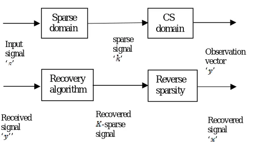
The fundamental concept of compressive sensing technique is given in Fig.1. It contains two sections namely, a transmitter part and a receiver part. Let ‘x’ be any input signal. As said, most of the data is sparse in nature. If it is not sparse then such data can be made sparse by employing certain transforms like DCT, DFT, etc. Here a basis vector is multiplied with the signal to make it sparse in nature. This results in K-sparse signal, where K is degree of sparseness, for which the signal is compressed. Compression sensing does not mean squeezing of a signal, it means randomly selecting some of the samples.
Assume a signal , let’s consider that this signal is not sparse. Therefore it has to be made sparse by multiplying it by a basis vector
. Let signal which is represented as,
(1)
Where, ‘ ’ is a N x 1 column vector
‘ ’ is a N x N basis vector is a N x 1 sparse signal.
The signal ‘x’ represents a K-sparse signal, which has ‘x’ has K-nonzero elements in it. The observation vector is depicted as follows
(2)
‘ ’ and ‘ ’ are measurement matrices
[image:3.612.105.353.122.261.2]‘ ’ is an sparse signal.
Fig 2.1 Block diagram of Transmitter and Receiver.
A prominent relation to be considered here is,
In compressive sampling, there are two major concerns. They are,
Designing of an effective and robust sensing matrix which protects all information in ‘ ’. Design of speedy and robust recovery algorithm. [4][5].
A. Sensing matrix
Sensing matrix is the vital part of the compressive sensing method. It aids in taking the linear projection of samples. Robust and
effective design of sensing matrix is necessary for the error less reconstruction of the signal. To reconstruct the signal
completely, sensing matrix has to satisfy two properties, namely, Restricted Isometric Property (RIP) and incoherence property. Restricted Isometry Property:
For an arbitrary constant α, sensing matrix should satisfy the below condition.
(3)
Where, ‘ is a 3 K-sparse vector and it has the similar non-zero positions of zeros as that of input data .
B. Incoherence Property
This condition says that the rows of sensing matrix , must be in coherence with the columns of the basis vector . If this condition is not found true, then the multiplication of sensing matrix and basis vector will give an identity matrix and this leads in backsliding the compressive sensing technique. To validate and verify if the sensing matrix is in ordinance with the RIP and property of incoherence is a complex and tedious method. Hence randomly generated or deterministic sensing matrices are easy to use as a sensing matrix.
The major difficulty with the random matrix sensing matrix is that it takes large reconstruction time period which may lead to unusual delay. The random measurement matrix gives different output for the same set of input parameters. On the other hand, predefined matrix helps to provide similar results every iteration. In this paper a novel deterministic sensing matrix is designed and used in the reconstruction of the signal.
III. DESIGN FOR WATERMARKING ALONG WITH COMPRESSION SENSING
Discrete Wavelet Transformation has gained a wide popularity because of its exceptional quality in watermarking, image compression. Sparse domain d CS domain Input signal ‘ ’ sparse signal
Fig 3.1: Single level decomposition
The wavelets from the Discrete Wavelet Transform will contain more energy in lower frequency bands and less information in higher frequency bands. This is advantageous because human eye is sensitive to lower frequency and less sensitive or insensitive to the higher frequency. This helps in embedding an image in higher frequency which aids in watermarking the image. The decomposition of image is done along the horizontal and the vertical manner. The decomposition can be classified into LL1, LH1, HL1 and HH1. The HH1 decomposed part needs to be more used in case of watermarking since it contains the higher frequency component of signal.
IV. METHODOLOGY FOR WATERMARKING USING COMPRESSION SENSING
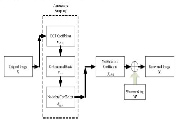
In the process of watermarking the original image is gone through compression sensing primarily and then a visible watermark is embedded. In the process of compression sensing primarily a Discrete Cosine Transform is applied to the image. We obtain a set of N*N components which is a subset of the original image. This DCT transform matrix is multiplied with the sensing matrix. This results in an observation matrix which has the data in a compressed manner.
Fig 4.1: Watermark embedding with compression sensing
[image:4.612.139.511.422.669.2]A. Flow Chart for CS Watermarking
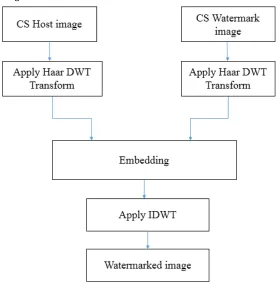
Fig 4.2: Compression sensed Watermarking
The above figure4.2 depicts the flow diagram for compression sensed watermarking. The host image is compression sensed and the image to be watermarked is also compression sensed. The compression sensing is applied for both the host and watermark image. This helps in both the images to have qualities that are contributed by compression sensing. The qualities are like reduced size, encrypted image which help in easy embedding of watermark over the host image.
Both compression sensed host and watermark images are applied for Haar DWT transform, the Haar transform results in lower frequency and higher frequency. Embedding of watermark on host image is taken place in higher frequency of the host image. After embedding of watermark on host image an inverse DWT transform is applied to get the watermark embedded final image.
V. RESULTS
Experiment is conducted on an image source in Matlab2013a with i3 Intel core processor Clock frequency at 2.60 Hz. The size of image is 256*256, that is N=256 in this case.
[image:5.612.395.539.557.686.2]
Fig 5.1: Host image Fig 5.2: Watermark image
Fig 5.3: Reconstructed CS host image (K=250) Fig 5.4: Reconstructed CS watermark image (K=250)
The above host and watermark images are compression sensed and recovered by applying inverse DCT. These images are reconstructed by using K=250 number of iterations in OMP algorithm. These are the images used for watermarking.
[image:6.612.95.219.88.208.2]
Fig 5.5: Reconstructed CS host image (K=100) Fig 5.6: Reconstructed CS watermark image (K=100)
The above host and watermark images are compression sensed and recovered by applying inverse DCT. These images are reconstructed by using K=100 number of iterations in OMP algorithm. These are the images used for watermarking.
[image:6.612.117.529.297.442.2]
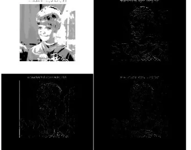
Fig 5.7: DWT of the CS host image (K=250) Fig 5.8: DWT of the CS watermark image (K=250)
[image:6.612.88.532.485.640.2] [image:6.612.84.271.489.636.2]
Fig 5.9: Watermarked image with K=250 Fig 5.10: Watermarked image with K=100
Above two images are watermarked that consists of two separate compression sensed host and watermark images that are reconstructed with K=250 and K=100 respectively.
V. CONCLUSION
In this paper an idea of watermarking along with compression sensing is discussed. The method of compression sensing along with watermarking results in stronger and better watermarking compared to other techniques of watermarking. This technique helps in providing better security options against attacks from intruders. Hence watermarking along with compression sensing helps in sustainability against attacks and it also proves to be better compared with traditional watermarking. The quality of watermarking can be increased by the use of sensing matrix having more number of elements with constraint in increased processing time.
VI.ACKNOWLEDGMENT
I would heartily extend my sincere thanks to Dr. Saroja V. Siddamal from whom I learnt the idea of Compression sensing, and also would like to thank our HOD Dr. Arunkumar G, for encouraging us to pursue the research work in the college. Without your support and well wishes I find hard to carry my work.
REFERENCES
[1] Heung-no Lee, “Introduction to Compressive sensing”, GIST Korea, August 2011, pp 16-39.
[2] Siddhi Desai, Prof. Naitik Nakrani, “Compressive sensing in speech processing: A survey based on sparsity and sensing matrix”, IJETAE, vol. 3, issue 12, December 2013.
[3] Siddhi Desai, Prof. Naitik Nakrani, “Evaluating the performance of Compression Sensing for Speech Signal with Various Bias” International Journal of Computer Application (0975-8887), vol. 94, No. 11, May 2014.
[4] David Donoho, “Compressive Sensing”, IEEE Transactions on Information Theory, Vol. 52, No. 4, April 2006.
[5] K. V. Siddamal, Shuba P. Bhat “Fixing of Sensing Matrix for Speech Signal Reconstruction using OMP” IOSR Journal of Electronics and Communication Engineering (IOSR-JECE). Volume 11, Issue 5, Ver. I (sep-oct-2016), PP 61-64.
[6] Thong T. Do, Student Member, IEEE, Lu Gan, Member, IEEE, Nam H. Nguyen and Trac D. Tran, Senior Member, IEEE. “Fast and Efficient Compressive Sensing using Structurally Random Matrices”. IEEE Transactions on signal Processing, Vol XXX, No. XXX,XXX 2011.
[7] Joel A. Tropp and Anna C. Gilbert, “Signal Recovery from Random Measurements via Orthogonal Matching Pursuit”, IEEE Transactions On Information Theory, Vol. 53, No. 12, December 2007.
[8] ”An Introduction to Compressive sampling.", IEEE signal ProcessingMagazine, Vol.25, Issue.2, pp.21-30,
[9] E. Candes and M. Wakin, “An introduction to compressive sampling,”IEEE Sig. Proc. Magazine, vol. 25, no.2, pp. 21–30, March 2008.